1
[AK4646]
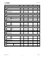
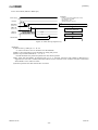
3. PLL Slave Mode (MCKI pin)
Example:
Audio I/F Format: MSB justified (ADC & DAC)
BICK frequency at Master Mode: 64fs
Input Master Clock Select at PLL Mode: 11.2896MHz
MCKO: Enable
Power Supply
(1) Power Supply & PDN pin = “L” Æ “H”
(1)
PDN pin
(2)
(3)
(2)Addr:04H, Data:4AH
Addr:05H, Data:27H
PMVCM bit
(Addr:00H, D6)
(4)
MCKO bit
(Addr:01H, D1)
(3)Addr:00H, Data:40H
PMPLL bit
(Addr:01H, D0)
(5)
MCKI pin
(4)Addr:01H, Data:03H
Input
40msec(max)
(6)
MCKO pin
MCKO output start
Output
(7)
(8)
BICK pin
LRCK pin
Input
BICK and LRCK input start
Figure 40. Clock Set Up Sequence (3)
<Example>
(1) After Power Up: PDN pin “L” Æ “H”
“L” time of 150ns or more is needed to reset the AK4646.
(2) DIF1-0, PLL3-0, FS3-0, BCKO and M/S bits should be set during this period.
(3) Power Up VCOM: PMVCM bit = “0” Æ “1”
VCOM should first be powered up before the other block operates.
(4) Enable MCKO output: MCKO bit = “1”
(5) PLL starts after that the PMPLL bit changes from “0” to “1” and PLL reference clock (MCKI pin) is supplied.
PLL lock time is 40ms (max).
(6) The normal clock is output from MCKO after PLL is locked.
(7) The invalid frequency is output from MCKO during this period.
(8) BICK and LRCK clocks should be synchronized with MCKO clock.
MS0557-E-06
2011/06
- 69 -