1
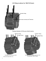
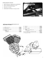
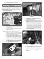
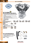
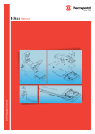
®
Instruction 51-1255
11-29-11
Copyright®, 2003, 2006, 2008, 2009
by S&S Cycle, Inc.
All rights reserved.
Printed in the U.S.A.
S&S Cycle, Inc.
14025 County Highway G PO Box 215
Viola, Wisconsin 54664
Phone: 608-627-1497 • Fax: 608-627-1488
Technical Service Phone: 608-627-TECH (8324)
Technical Service Email: [email protected]
Website: www.sscycle.com
Installation Instructions: S&S® Crankcase for
Harley-Davidson® Twin Cam 88® Engines
For all S&S Stock Bore, 4" Bore, and 41/8" Bore Twin Cam 88® engine cases
with 1999-2006 and 1984-1999 engine mounts.
DISCLAIMER:
IMPORTANT NOTICE:
S&S parts are designed for high performance, closed course, racing
applications and are intended for the very experienced rider only. The
installation of S&S parts may void or adversely effect your factory
warranty. In addition such installation and use may violate certain
federal, state, and local laws, rules and ordinances as well as other laws
when used on motor vehicles used on public highways, especially in
states where pollution laws may apply. Always check federal, state, and
local laws before modifying your motorcycle. It is the sole and exclusive
responsibility of the user to determine the suitability of the product for
his or her use, and the user shall assume all legal, personal injury risk and
liability and all other obligations, duties, and risks associated therewith.
Statements in this instruction sheet preceded by the following words
are of special significance.
The words Harley®, Harley-Davidson®, H-D®, Sportster®, Evolution®, and
all H-D part numbers and model designations are used in reference only.
S&S Cycle is not associated with Harley-Davidson, Inc.
S&S recommends you take special notice of these items.
SAFE INSTALLATION AND OPERATION RULES:
Before installing your new S&S part it is your responsibility to read and
follow the installation and maintenance procedures in these
instructions and follow the basic rules below for your personal safety.
Gasoline is extremely flammable and explosive under certain
conditions and toxic when inhaled. Do not smoke. Perform installation
in a well ventilated area away from open flames or sparks.
If motorcycle has been running, wait until engine and exhaust pipes
have cooled down to avoid getting burned before performing any
installation steps.
Before performing any installation steps disconnect battery to
eliminate potential sparks and inadvertent engagement of starter while
working on electrical components.
Read instructions thoroughly and carefully so all procedures are
completely understood before performing any installation steps.
Contact S&S with any questions you may have if any steps are unclear
or any abnormalities occur during installation or operation of
motorcycle with a S&S part on it.
Consult an appropriate service manual for your motorcycle for correct
disassembly and reassembly procedures for any parts that need to be
removed to facilitate installation.
Use good judgment when performing installation and operating
motorcycle. Good judgment begins with a clear head. Don't let
alcohol, drugs or fatigue impair your judgment. Start installation when
you are fresh.
Be sure all federal, state and local laws are obeyed with the
installation.
For optimum performance and safety and to minimize potential
damage to carb or other components, use all mounting hardware that
is provided and follow all installation instructions.
Motorcycle exhaust fumes are toxic and poisonous and must not
be inhaled. Run motorcycle in a well ventilated area where fumes
can dissipate.
WARNING
Means there is the possibility of injury to yourself or others.
CAUTION
Means there is the possibility of damage to the part or motorcycle.
NOTE
Other information of particular importance has been placed in italic type.
WARRANTY:
All S&S parts are guaranteed to the original purchaser to be free of
manufacturing defects in materials and workmanship for a period of
twelve (12) months from the date of purchase. Merchandise that fails
to conform to these conditions will be repaired or replaced at S&S’s
option if the parts are returned to us by the purchaser within the 12
month warranty period or within 10 days thereafter.
In the event warranty service is required, the original purchaser must
call or write S&S immediately with the problem. Some problems can be
rectified by a telephone call and need no further course of action.
A part that is suspect of being defective must not be replaced by a
Dealer without prior authorization from S&S. If it is deemed necessary
for S&S to make an evaluation to determine whether the part was
defective, a return authorization number must be obtained from S&S.
The parts must be packaged properly so as to not cause further damage
and be returned prepaid to S&S with a copy of the original invoice of
purchase and a detailed letter outlining the nature of the problem, how
the part was used and the circumstances at the time of failure. If after
an evaluation has been made by S&S and the part was found to be
defective, repair, replacement or refund will be granted.
ADDITIONAL WARRANTY PROVISIONS:
(1) S&S shall have no obligation in the event an S&S part is modified by
any other person or organization.
(2) S&S shall have no obligation if an S&S part becomes defective in
whole or in part as a result of improper installation, improper
maintenance, improper use, abnormal operation, or any other misuse
or mistreatment of the S&S part.
(3) S&S shall not be liable for any consequential or incidental damages
resulting from the failure of an S&S part, the breach of any warranties,
the failure to deliver, delay in delivery, delivery in non-conforming
condition, or for any other breach of contract or duty between S&S and
a customer.
(4) S&S parts are designed exclusively for use in Harley-Davidson® and
other American v-twin motorcycles. S&S shall have no warranty or
liability obligation if an S&S part is used in any other application.
Oil Fitting Locations For 1984-’99 Chassis
Breather Fitting
Oil Pressure Switch, H-D® 26561-99
Crankcase Breather & Oil Pressure Switch Location
Oil Return Fitting
Oil Supply Fitting
Oil Supply & Return Fitting Locations
2
*Non-counter balanced only.
Oil Return Fitting
Oil Supply Fitting
Oil Supply & Return Fitting Locations for some
Harley-Davdison® Dyna® Models
Please read these instructions thoroughly before starting work.
Proceed with the installation only after they are completely
understood. These instructions should be supplemented by the
appropriate OEM service manual for your motorcycle. Follow all
safety information.
INTRODUCTION
S&S® crankcase assemblies for Harley-Davidson® Twin Cam 88®
non-counterbalanced engine applications. Installation can be
performed by any Harley-Davidson® repair shop equipped to do
complete engine overhauls. No special tools other than those
used in normal engine building operations are required.
Stock bore cases are perfect for stock replacement applications,
4" bore cases are a natural for use with the S&S® Hot Set Up Kit®
for Twin Cam 88, and 41⁄8 bore cases make it possible to build
really large displacement custom engines.
S&S® Crankcases for 1999-’06 Big Twin Engines
Bore Size
Stock Bore
4" Bore
Silver
106-4039
106-4041
Black
31-0172
31-0175
Polished
N/A
N/A
41⁄8” Bore (Stock Stud Pattern)
41⁄8" Bore (S&S Stud Pattern)
106-4057
106-4043
31-0181
31-0178
31-0182
31-0179
NOTE: S&S crankcases are sold in matched sets only. Individual
case halves are not available.
ADDITONAL OIL LINE INSTALLATION KIT REQUIRED
Dyna® - PN 31-0424
FL - PN 31-0425
ADDITIONAL FEATURES:
Greater overall strength than stock crankcases, especially in
the front motor mount, an important consideration in high
performance applications.
All oil passages between the crankcase and gear cover are
o-ring sealed.
Compatible with stock components. Use stock oil pump, cam
support plate, gear cover, etc.
1999-2002 Timken® style sprocket shaft bearing. (Included)
Uses 2003-up pinion shaft bearing
Special order crankcases offer your choice of cylinder spigot
bore, cylinder stud pattern, and your choice of rear motor
mount style - 1999-06 or 1984-1999.
KIT CONTENTS
Crankcase with camshaft bearings and cylinder studs installed
Sprocket Shaft Bearings
S&S Reed Valve Assembly
Pinion Bearing
Hardware Package
Certificate of Origin
Instructions
POLISHING, PAINTING, PLATING, OR POWDERCOATING S&S CASES
S&S Cycle cautions against modifying these crankcases due to the
possibility of damaging or weakening them. Modifying S&S
crankcases in any fashion voids all manufacturer warranties.
Should the customer elect to modify the crankcases regardless, it
is imperative that they and the information tag attached to them
be inspected beforehand to confirm that the correct model, style,
bore size, etc. have been provided. The customer must confirm
that crankcases and related parts are correct before assembling
them or having them modified in any manner, and assumes all
liability for modifications.
The customer must also verify that the serial numbers on the
crankcase and attached information tag correspond with those
on the certificate of origin and packing carton.
Under no circumstance will S&S be held responsible for expenses
related to the modification of any S&S part in the event warranty
service is required. Modified parts will not be accepted for credit
or exchange. This will apply regardless of cause or fault:
customer, retailer, manufacturer, or other.
For further information, contact S&S Technical Services at
608-627-8324, FAX 608-627-1488 or e-mail [email protected]
NOTE: Modification includes but is not limited to appearance
changes such as painting, powdercoating, plating, and polishing.
Proper preparation for these procedures as well as the processes
themselves may require the use of polishing compounds,
chemicals or procedures that are potentially harmful to
crankcases.
CAUTION
Passages and internal cavities may become obstructed by
residues from materials used to polish, paint, plate or
powdercoat surfaces. Additionally, surface finishing processes
can damage critical machined surfaces. Any of the above may
cause premature wear, damage or failure of other engine
components as well as the crankcases themselves.
Powdercoating - Subjecting heat-treated alloys such as those
used in S&S® crankcases to excessive heat can drastically alter
their strength and their critical properties. The degree of change
depends upon the temperatures reached and the duration of
exposure. When powder coating or otherwise processing alloy
parts, S&S exposes them to a maximum temperature of 370°F for
no longer than 20 minutes. Under no circumstances should parts
be heated past 400°F!
3
PREPARATION AND INSTALLATION
1-
Inspection
a-
Inspect crankcases to confirm that they are correct style
and machined for correct bore size. Refer to tag wired
to crankcases.
b-
Verify that serial numbers on crankcases match numbers
on packing carton and certificate of origin. Contact S&S
immediately if numbers do not match.
NOTE: Valid certificate of origin is required for any transfer or
sale of aftermarket crankcases or complete engines built with
aftermarket crankcases. Certificate of origin is required to title
and license any motorcycle which is to be driven on public streets
and highways.
2-
Crankcase Test Fit
If possible, bare crankcase should be positioned in motorcycle
frame before assembly to check clearances.
a-
Test-fit instructions for S&S crankcases with 1999-06
engine mounts.
Position case in frame, check for clearance at frame, and
alignment to transmission. It is a good idea to replace
rubber engine and transmission mounts at this time. Old
mounts deform over time and may and induce
unwanted stresses on the engine case.
b-
Test-fit instructions for S&S crankcases with 1984-1999
engine mounts.
S&S crankcase for 1999-06 models being installed in
1984-1999 frames is essentially the same as
stock,
although additional clearancing and shimming may
occasionally be required. When this style of case is solid
mounted instead of rubber mounted, additional care
must be taken in installing the case. Main areas of
concern are between cases and frame motor mounts.
Checking clearance around and between case mounting
bosses and frame is necessary to ensure that crankcase
rests squarely on motor mount pad and no stress is
applied to crankcases when mounting bolts are
tightened. Shimming may be required to compensate
for variances between frames. The oil lines for the
T124V engine connect to the engine on the bottom rear
of the cam chest. The supply to the engine is the pipe
thread on the right marked with an S. There are two
pipe threads for the return oil located to the left of the
supply pipe thread and marked with an R.
NOTE: Crankcases damaged by improper installation are not
covered under warranty.
CAUTION
Improper alignment of engine and frame mounts may cause
abnormal stresses resulting in damage to crankcases or
other parts.
4
To check clearance perform following steps:
1- Assemble case halves using case bolts. Tighten to snug.
Torquing bolts to final specification is not necessary.
2- Clean frame engine mounts and carefully remove any
irregularities from mounting surfaces. Also inspect crankcase
mounting bosses for burrs.
3- Position case assembly in frame.
4- Install engine mounting bolts in motor mounts, and check
clearance between mounting bosses on cases and frame and
any other areas where frame and cases may contact each
other. Bolts may be difficult to install if contact is severe.
5- If cases contact frame, remove them and relieve just enough
material in offending area to provide clearance.
6- Place cases in frame, install one rear mounting bolt and
snug nut.
7- Measure gap between crankcase mounting bosses and
frame motor mounts with feeler gauge to determine if
shimming is required.
8- If gap exists, fabricate shim just thick enough to fill gap.
9- Install opposite corner shim and mounting bolt and nut, and
tighten identical to other bolt.
10- Check other corners with feeler gauge to confirm
thickness required is same as before. If not, determine
cause and correct.
3-
Pre-Assembly Cleaning
Clean crankcases in hot soapy water or solvent to remove
any dirt or contamination which may have been introduced
during shipping, handling, or set-up. Dry components and
check passages with compressed air.
WARNING
Compressed air and particles dislodged by compressed air are
potentially harmful. Wear protective goggles when using
compressed air and always direct air stream away from
yourself and others nearby.
Hardware Identification and Installation
NOTES
When installing hardware, be careful not to cross-thread
fittings or damage threads. Damage caused by improper
installation of hardware will not be covered under warranty.
To prevent galling, apply anti-seize compound, pipe sealant,
or Teflon® tape to threads of all steel fittings prior to
installation in crankcase.
If Teflon tape is used, loose tape must not enter crankcase or
oil passages. Do not apply tape to first 2-3 threads that screw
into hole. If fittings are removed or replaced be sure no tape
shreds remain in holes. Tape shred could block oil passages
causing restriction of oil flow.
CAUTION
Restricted oil flow may result in extensive engine damage not
covered under warranty.
4-
NOTE: Apply thread sealant to all tapered pipe threads.
3-
Piston Jet Installation
a-
Apply a thin film of clean engine oil to new O-ring.
b-
Seat O-ring in groove of piston jet mounting flange.
c-
With pinhole in the jet pointing upward, install using
two T20 TORX screws. Apply Loctite® 243 Blue, then
tighten to 20-30 in-lbs.
Remove crankcase vent fitting (S&S PN 50-0451)
and set aside for later use. Install supplied vent
fitting (S&S PN 50-0449 is for use with 2002-’06 with
7
⁄16 ID vent hose or 50-0454 is for use with 1999-’01
with 3⁄8 ID vent hose) with O-ring installed on fitting.
See Picture 1.
CAUTION
Piston jets must be installed using the correct o-ring. Leaving
out a piston jet o-ring, installing too small of an o-ring, or
pinching an o-ring at assembly will cause oil to by-pass the
jet, resulting in low oil pressure.
NOTE: Always use a new o-rings when re-installing jets.
5-
Oil Line Installation
a-
For 1999-2006 Harley-Davidson® FL models
CAUTION
Oil line installation is crucial to engine life. If you are not sure
that you can properly perform this operation, please contact
the S&S Tech Department for a referral to a shop in your area.
NOTE: Installation instructions are based on an engine and
transmission already in the chassis.
Picture 1 (2002-’06 Shown)
4-
Install the vent hose and clamp (S&S PN 50-8156 or
50-8076-S) on the new fitting.
NOTE: The stock vent hose is reused in this step.
5-
Position a drain container in front of the oil pan.
Next, locate and remove the two plugs on the
forward face of the oil pan allowing the oil to
drain. Once the oil is completely drained, replace
the 3/8” pipe-plug with a 90-degree fitting (S&S
PN 50-8288). Position barb of fitting toward
right side of bike at an angle slightly above
horizontal as shown in Picture 2. Next, install the
oil return fitting (S&S PN 50-0451) with O-ring
(S&S PN 50-8008) in the drain plug location.
Supply
Return
FL Oil Line Install Kit (PN 31-0425)
NOTE: Apply thread sealant to all tapered pipe threads.
12-
Remove the stock oil supply and return fittings
from the transmission.
Install two supplied 3⁄8 NPT pipe plugs (S&S PN 50-8330)
in the oil fitting location.
Picture 2
5
6-
Remove cover plate that was shipped on
crankcase from the bottom surface of the rear
motor mount. The oil line block will be installed
in this location. Assemble the oil line block by
installing the 90-degree fitting (S&S PN 50-8288)
and the oil return fitting (S&S PN 50-0451) with
O-ring (S&S PN 50-8008) into the block, as shown
in Picture 3.
9-
Remove the oil line block from the engine case.
Install the supplied clamps (S&S PN 50-8156) on the
lines between the fittings. See Picture 5.
Picture 5
10- Install O-Rings (S&S PN 50-8066) in the counter
bores of the oil line block. Position the oil line block
on the engine case and tighten the screw to 18 ftlbs. of torque with blue threadlock on the threads.
See Picture 6.
Picture 3
7-
8-
Mount the oil line block on the crankcase using 5⁄1618 x 13⁄4” long screw (S&S PN 50-0437)—do not final
tighten as it will be removed again.
The next step is to measure and then cut the oil
hoses. The straight hose connects the 90 degree
fittings of the oil line block and oil pan. The bent
hose runs between the oil return fittings on the oil
line block and oil pan. See PIcture 4.
Picture 6
Supply
Picture 4
6
Return
11- Position hose clamps over the fittings.
12- Refill oil reservoir.
13- Start engine and check for oil leaks.
To Change Engine Oil in the Future
1-
Slide hose clamp off of fitting along hose. See Picture 7.
2-
Place an oil drain pan under front of oil pan.
3-
Remove hose from fitting to drain oil.
4-
Reinstall hose and clamp.
5-
Continue with recommended oil change procedure.
Picture 7
S&S® Oil Line Installation Kit Replacement Parts for
Harley-Davidson® FL Models
12345-
Block, oil line ............................................................31-0430
BHSHCS, 5⁄16-18 x 13⁄4 ...................................................50-0437
O-ring (10 pack) .........................................................50-8066
Fitting, pipe, 90 degree...........................................50-8288
Fitting,
7
⁄16 (2002-’06)..........................................................50-0449
3
⁄8 (1999-’01) ..........................................................50-0454
6789-
Fitting, 1⁄2....................................................................50-0451
O-ring ........................................................................50-8008
Hose, oil supply ........................................................50-8157
Clamp,
Double wire spring (5 pack) .................................50-8293
Hose, spring.......................................................50-8076-S
10- Hose, return oil line, 90 degree bend....................50-8291
11- Plug, pipe (3⁄8 NPT) ....................................................50-8330
7
b-
For 1999-’05 Harley-Davidson® Dyna® models
CAUTION
Oil Line installation is crucial to engine life. If you are not sure
that you can properly perform this operation, please contact
the S&S® Tech Department for a referral to a shop in your area.
NOTE: Installation instructions are based on an engine and
transmission already in the chassis.
Picture 8a
5-
6-
7-
Dyna® Oil Line Install Kit (PN 31-0424)
12-
Remove the stock oil supply and return fittings
from the transmission.
Install two supplied 3⁄8 NPT pipe plugs (S&S PN 50-8330)
in the oil fitting location.
Remove the transmission top cover. Remove the
neutral indicator switch, vent line and fitting from
the transmission top cover.
Install the neutral indictor switch, vent line and
fitting on the new S&S transmission top cover (S&S
PN 56-1615).
Slide the oil feed line (S&S PN 31-0442) through the
hole in the top cover closest to the oil filler/dipstick
boss. Place a new top cover gasket (S&S PN 56-1256)
on the transmission case and position the new S&S
top cover on it. Rotate the oil feed line so it will pass
through the 1⁄2” hole in the baffle. Be sure the bend
in the oil feed line orientation is to the rear of the
motorcycle. See Picture 9.
NOTE: Apply thread sealant to all tapered pipe threads.
3-
4-
Drain the oil from the oil pan—see the proper
factory service manual for instructions—and then
remove the oil pan from the motorcycle.
Place the supplied template (53-0080) over the oil
pan baffle and use a scribe to mark the location of
the 1⁄2” hole as shown in Picture 8. Use a drill press to
machine the 1⁄2” hole as marked in Picture 8a. Use a
small file or deburring tool to make sure no chips or
pieces are left on the 1⁄2” hole and then clean the oil
pan and baffle with solvent before reinstalling the
pan with a new gasket on the motorcycle.
Picture 9
8-
8
Picture 8
Install the transmission top cover screws and
washers according to Detail A. Use blue
threadlock on the screws, but leave them loose at
this time. See Detail A in exploded view of
replacement parts for Harley-Davidson® Dyna® on
page 10.
9-
Remove the oil line retention plate, plugs and seals
from the top of the engine crankcase. Remove seals
from the plugs. Discard the plugs.
11- Position oil line assembly on both the transmission
top cover and crankcase and press down until lines
are firmly seated in the counterbores in the
crankcase and transmission cover.
Picture 10
Picture 11
10- To install the oil lines (S&S PN 31-0444 and 31-0443),
orient the ends and openings so they are parallel.
Insert the lines through the oil line retention plates,
then the included washers (S&S PN 50-0439) and,
last the seals (S&S PN 50-8271) on each line end.
The ends of the lines should protrude through the
seals about 1⁄8 inch.
12- Press the oil line retention plates into place until
they seat. Install the two screws (5⁄16-18 x 3⁄4 button
head) through the oil line retention plates. First
screw goes in the transmission top cover and the
second mounts into the crankcase near the rear
motor mount. Treat both screws with blue
threadlock and tighten to 18-ft-lbs.
13- Tighten transmission top cover screws to 100-120 in-lbs.
14- Install the vent line (S&S PN 50-8291) with clamps
(S&S PN 50-8156).
15- Reconect neutral switch wires.
16- Check function of neutral switch.
9
S&S® Oil Line Installation Kit Replacement Parts for
Harley-Davidson® Dyna® Models
12345678910111213141516171819202122-
Plate ..........................................................................50-0440
Seal ............................................................................50-8271
BHSHCS 5⁄16-18 x 3⁄4 ......................................................50-0438
Washer ......................................................................50-0439
Line, oil supply .........................................................31-0444
Line, oil return..........................................................31-0443
Line sssembly, Oil feed.............................................31-0442
Top cover ..................................................................56-1615
SHC - 1⁄4-20 x 11⁄2” .......................................................50-0255
SHC - 1⁄4-20 x 21⁄4" .......................................................50-8455
SHC - 1⁄4-20 x 13⁄4" .......................................................50-8458
SHC - 1⁄4-20 x 11⁄4" .......................................................50-7463
Washer ......................................................................50-8451
Gasket, tranny top cover.........................................56-1256
Template ...................................................................53-0080
Fitting........................................................................50-8289
Hose, 90 degree bend .............................................50-8291
Clamp ........................................................................50-8156
Plug, pipe (3⁄8 NPT) ...................................................50-8330
O-ring ........................................................................50-8008
Fitting........................................................................50-0451
Drill Template ...........................................................53-0080
11
10
6-
Crankcase Cylinder Studs
a-
S&S crankcases for Harley-Davidson Twin Cam 88 engines
are shipped with cylinder studs installed Before assembling
engine, verify that the lower collar of each stud is contacting
the case deck, and that the studs are torqued to 10 ft.-lbs.
®
®
®
Use only S&S #31-2325 stud in
S&S crankcases for Twin Cam 88®.
Threaded end with collar is .230”
shorter than OEM studs (clearance
requirements)
Sprocket shaft bearings: Use 1999-2002 style taper roller
bearings, included with the crankcase. They must be
used with a 1999-2002 style flywheel assembly,
purchased separately.
CAUTION
Installing and setting the clearances for 1999-2002 style taper
roller bearings is a critical operation. install and set clearances
per 1999-2002 Harley-Davidson service manual.
NOTES
S&S crankcases secure the pinion bearing in place with a
snap ring. 2003-up Harley-Davidson cases do not.
1999-2002 pinion shaft bearing is not compatible with S&S
crankcases. It has a larger outside diameter than the 2003up style used by the S&S cases.
a-
Removal
12-
b-
Thread two 3⁄8”-16 nuts onto end of stud and
tighten them together.
Use a wrench on the lower nut to remove stud.
Camshaft And Cam Plate Installation
S&S Camshafts install using the instructions packaged with
them. Harley-Davidson camshafts install per 1999-2003 Twin
Cam 88® service manual.
9-
S&S Reed Valve Installation
The S&S Reed Valve Assembly 31-2071 included with the
crankcase is an effective way to control internal air pressures
inside the crankcase, reducing oil carry over, blow-by, and oil
leakage. It is a one-way valve that allows for the smooth
passage of air through and out of the engine breathing
system. Installation of the S&S Reed valve is optional. It is not
required for crankcase assembly. However, its use is highly
recommended. It installs easily, and requires no extra
machining. A separate Instruction sheet is packaged with the
Reed Valve. See Picture 12.
Installation
1-
2-
Place a ball bearing into the end of a head bolt
then place the head bolt on end of the stud
without a collar.
Screw stud into the case, collar side down, until
collar contacts case. Torque stud to 10-ft.-lbs.
CAUTION
Do not carry the crankcase by the studs. It stresses the
crankcase and studs in ways they are not designed to handle.
Also, it is easy to drop and damage the case when it is carried
by the studs.
7-
8-
Flywheel Assembly
S&S® crankcases for Harley-Davidson® Twin Cam 88® engines
are designed to use any S&S flywheel assembly, or 1999-2002
Harley-Davidson flywheel assembly.
S&S Reed Valve assembly and wave washer
NOTE: 2003-up Harley-Davidson® flywheel assemblies will not fit
in S&S crankcases. For 2003, Harley-Davidson started using a flat
roller bearing on the sprocket shaft. S&S cases must use flywheel
assemblies that use dual taper roller bearings.
NOTE: 2003-up flat roller sprocket shaft bearing is not compatible
with S&S cases
CAUTION
It is not recommended to attempt using a 2003-up flywheel
assembly by changing the sprocket bearing from the flat
roller style to the earlier dual taper style. The sprocket
bearing inner race of the 2003-up sprocket shaft is a nonserviceable item, per the OEM service manual. Attempting to
remove the pressed on sprocket bearing inner race from the
sprocket shaft of 2003 Harley-Davidson® flywheel assemblies
can easily result in serious damage to the flywheel assembly.
Picture 12
10- Oil Pump, Lifters, Lifter Covers, and Cam Cover Installation
These and any other crankcase components not listed install
per 1999-2003 Harley-Davidson® Twin Cam 88® service
manual.
11
Replacement Parts for S&S® Crankcases for Harley-Davidson® Twin Cam 88® Engines
1. Bolt, stator 10-24 x1" SHC - 4 required (H-D® #2720)
Each......................................................................................50-0044
10 pack .................................................................................50-0194
2. Seal, sprocket shaft (H-D® #12068)..................................... 31-4035
3. Bearing, Timken® sprocket shaft (H-D ®#9028) ................... 31-4013
4. Timken Main Bearing Spacers
Fits 11⁄4" stock diameter shaft.
.0995" - .1005" (H-D® #9124................................................31-4071
.1015" - .1025" (H-D® #9125)...............................................31-4072
.1035" - .1045" (H-D® #9126) ..............................................31-4073
.1055" - .1065" (H-D® #9127) ..............................................31-4074
.1075" - .1085" (H-D® #9128) ............................................. 31-4075
.1195" - .1205" (H-D® #9134) ..............................................31-4076
5. Hardware Kit, 4" Bore, S&S 41⁄8" Bore,1999-'12 bt
Chrome...............................................................................106-4905
Zinc.....................................................................................106-4904
6. Bolt, case 5⁄16" -18 x 31⁄2" HHC - 8 required
Chrome (each)...................................................................50-0254-S
6 pack.................................................................................106-3452
Zinc (each)............................................................................50-0117
7. Washer, flat 5⁄16" x 11⁄16" x 1⁄16" - 8 required.........................50-7034
8. Bolt center case 1⁄4" -28 x 6" HHC Grade 8
Each......................................................................................50-0020
5 pack ...................................................................................50-0221
9. Washer, flat, 1⁄4" x .474" x .050"
Each......................................................................................50-7020
10 pack .................................................................................50-7076
10.Nut 1⁄4"-28 Grade 8 - 1 required ...........................................50-5011
11.Cylinder stud - 8 required (H-D® #16834-99A)
Each................................................................................. 31-2325-S
8 pack.................................................................................. 31-2340
26.Piston Oiler Jet Kit (H-D® #22371-99)
Each ...................................................................................31-2025B
2 pack ...................................................................................31-2026
Piston Oiler Jet Kit includes:
a. O-ring,(-014),.500" ID x .625" OD (H-D® #11140, 11273)
Each...............................................................................50-8032
10 pack..........................................................................50-8130
b. Jet, Assembly, Piston Cooling (H-D® #22307-99)
Each ............................................................................31-2025B
c. Screw, Torx Panhead, 8-32 x 3⁄8", Zinc, Steel (H-D® #68042-99)
Each ...........................................................................50-0054-S
27.Hardware kit, oil line plugs...........................................................N/A
28.Fitting, crankcase vent,
1999-'00 ...............................................................................50-0454
2001-'06 (each)....................................................................50-0449
2 pack.................................................................................106-1171
29.Plate, oil line cover .............................................................106-1184
30.BHSH CS 5⁄16" -18 x 3⁄4" (10 Pack) .......................................106-1178
31.O-ring (H-D® #11105, 11275) (each) ....................................50-8008
10 pack .................................................................................50-8078
32. O-ring, 9⁄16" I.D. x 11⁄16" O.D. x 1⁄6" CS ...............................50-8034-S
33. Pin, dowel (H-D® #18535-99)
Each...................................................................................50-8195-S
2 pack ...................................................................................50-8195
12. Dowel, cylinder deck - 2 required (H-D® #16595-99A)
Each......................................................................................50-8177
4 pack ...............................................................................50-8177-4
10 pack .................................................................................50-8179
13. Bolt, cam plate 1⁄4" -20 x 1" SHC - 4 required (H-D® #4741A)
Each......................................................................................50-0084
10 pack .................................................................................50-0244
14. Bolt, cam plate 1⁄4" -20 x 11⁄4" SHC - 2 required (each).........50-0008
10 pack .................................................................................50-0153
15. O-ring, cam plate - 9 required (H-D® #11301) (each) .......50-8066-S
10 pack .................................................................................50-8066
16. Dowel, cam plate - 2 required (H-D® #16589-99A)..........50-8148-S
17. Bearing, inner cam (H-D® # 9198)........................................31-4080
18. Bearing, pinion shaft – Fits all S&S and OEM 2000-’02
(Balanced models only) & all OEM 2003-up
(H-D® #24604-00D)............................................................. 31-4085
19. Retaining ring, internal, spiraloc - 2 required
(H-D® #35114-02) .............................................................50-8160-S
20. O-ring, oil pump 11⁄16" I.D. x 15⁄16" O.D. x 1⁄8" CS
(H-D® #11190, 11157, 11293) ............................................. 50-8039
10 pack ................................................................................ 93-4110
21. Plug, magnetic drain .......................................................... 50-8335
22. Baffle plate .......................................................................31-0119-S
23. Screw 10-24 x 3⁄8" pan head - 2 required
Each......................................................................................50-0050
10 pack .................................................................................50-0139
24. Dowel, case alignment - 2 required (H-D® #16573-83)
Each......................................................................................50-8023
10 Pack .................................................................................50-8109
25. O-ring, case alignment,- 2 required (H-D® #26432-76A)
9
⁄16" I.D. x 11⁄16" O.D. x 1⁄6" CS ...........................................50-8034-S
These parts are for crankcases manufactured before 8-1-06:
34.Washer, flat 1⁄4" chrome (each) ............................................50-7017
12 pack .................................................................................50-7013
35.Bolt, 1⁄4" -20 x 3⁄4" SHCS (each).............................................50-0067
12 pack .................................................................................50-0144
36. Hose, oil, inlet/outlet ...........................................................50-8157
37. Spring clips .......................................................................50-8156-S
38. Oil line fittings, inlet/outlet - 2 required ......................................N/A
39. Oil line fitting- vent......................................................................N/A
40. Plug, sump (H-D® #765)...................................................... 50-8330
41. Oil conduit block...................................................................31-2076
11
11
12
11
NOT SHOWN:
42. Sensor, Kit, Crank Position, 1984-2007 bt
(H-D® #32707-01B) ............................................................. 55-1051
9
8
4
12
11
1
26
2
3
22
26c
33
26b
26a
9
6
24
10
15
7
16
14
25
38
23
36
40
17
18
19
21
38
19
27
37
32
36
34
29
31
41
35
13
16
39
37
12
20
15
28
21
14
30
All reference to H-D® part numbers is for identification purposes only. We in no way are implying that any of S&S Cycle’s
products are original equipment parts or that they are equivalent to the corresponding H-D® part number shown.