1
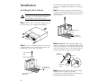
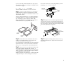
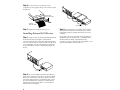
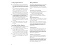
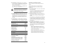
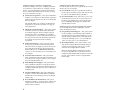
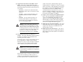
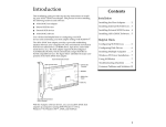
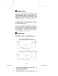
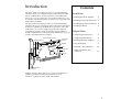
Introduction
Contents
The AHA®-2920C host adapter provides a powerful multitasking
interface between your computer’s PCI bus and SCSI devices (disk
drives, CD-ROM drives, scanners, tape drives, removable-media
drives, etc.). You can connect up to seven 8-bit SCSI devices to your
host adapter. The following figure shows the major components of the
AHA-2920C host adapter
The AHA-2920C host adapter provides a powerful multitasking
interface between your computer’s PCI bus and internal and external
SCSI devices (disk drives, CD-ROM drives, tape drives, removablemedia drives, etc.). The host adapter supports SCSI Configured
AutoMatically (SCAM), which automatically assigns SCSI IDs to
SCAM compatible devices. The figure below identifies the major components of the AHA-2920C host adapter.
50-pin Internal SCSI Connector
SCSI Terminator Chips
Installation
Installing the Host Adapter . . . . . 2
Installing Internal SCSI Devices . 3
Installing External SCSI Devices . 4
Installing Software . . . . . . . . . . . . 5
Helpful Hints
Configuring SCSI Devices . . . . . . 5
Configuring Disk Drives . . . . . . . 6
External LED
Connector
Installing Multiple Adapters . . . . 6
EEPROM
Using SCSISelect . . . . . . . . . . . . . . 6
BIOS
Troubleshooting Checklist . . . . . 10
40 Mhz Clock
Crystal
Common Problems and
Solutions . . . . . . . . . . . . . . . . . . 11
SCSI Chip
J3
50-pin High-Density External
SCSI-2 Connector
With the Adaptec software drivers, you can use AHA-2920C host
adapters in computers running DOS/Windows®, OS/2,
Windows® 95, Windows NT™, UNIX, and NetWare.
1
Installation
The PCI slot must support bus master data transfers
(refer to your computer documentation or contact your
vendor).
Installing the Host Adapter
Step 3: Insert the host adapter in the PCI expansion
WARNING: Before beginning the installation,
slot. Press it down firmly so that the contacts are securely
seated in the slot, and secure it with the screw that you
removed in step 2.
turn OFF power to the computer and external
devices and disconnect the power cords.
Step 1: Remove the cover from the computer case. (If
necessary, refer to your computer documentation.)
Bus contacts
PCI expansion slot
(typically white or ivory)
Back of
Your Computer
Step 4: OPTIONAL-Connect the host adapter to the
Step 2: Locate an unused PCI expansion slot. (This slot
is typically white or ivory.) Unscrew the expansion slot
bracket that covers the card-slot opening.
Expansion slot bracket
screw
LED on the computer so that it will light whenever there
is activity on the SCSI bus. To do this disconnect the LED
cable from the LED connector on the motherboard and
connect it to the LED connector on the host adapter.
LED cable
from motherboard
2-pin LED
cable
Expansion slot bracket
LED connector
on adapter
1
Pin 1
PCI expansion slots
(typically white or ivory)
Step 5: Make sure that all SCSI devices have unique
16-bit ISA expansion slot
(typically black)
2
SCSI ID’s from 0 to 6. (Refer to your device
documentation for SCSI ID settings and instructions on
manually changing the default settings.)
If you are installing external SCSI devices only, replace
the computer chassis cover and skip to Installing External
SCSI Devices on page 4.
Installing Internal SCSI Devices
Pin-1 of the connector is usually designated by a small
triangle (▲), or a “1” on the connector.
Colored stripe
(typically red or blue)
50-pin SCSI
ribbon cable
Step 1:
Install or enable terminators on the internal
SCSI device that you plan to connect to the end of the
internal cable. Then remove or disable terminators on all
other internal devices.
On most internal SCSI devices, you control termination
by setting a jumper or a switch, or by physically removing or installing a resistor module(s). Refer to the
device’s documentation to determine how to enable or
disable termination on your particular device.
Intenal SCSI
connector
Step 4: Plug the other end of the 50-pin internal SCSI
cable into the connector on the last internal SCSI device
in the chain. (This device must be terminated.) Make sure
the colored stripe on the side of the cable is aligned with
pin-1 of the SCSI device’s connector.
Pin 1
Colored stripe
(typically red or blue)
Termination
Enabled
Termination
Disabled
Internal SCSI
device
Step 2: Install and mount each internal SCSI device
Step 5: Plug the remaining cable connectors into any
inside your computer. (Refer to your computer and
device documentation for instructions.)
remaining internal devices. (These devices must not be
terminated.)
If you purchased your AHA-2920C as part of an Adaptec
kit, the kit includes one 50-pin internal SCSI cable that
allows you to connect up to two internal SCSI devices.
Step 3: Plug one end of your 50-pin internal SCSI cable
into the host adapter’s internal SCSI connector. To
connect more than two internal devices, you will need to
obtain or purchase a SCSI cable with enough connectors
to accommodate all of your devices.
Make sure that the colored stripe on one side of the cable
is aligned with pin-1 of the host adapter’s connector.
3
Step 6: Connect a DC power cable from your
computer’s power supply to the power connector on the
SCSI device.
DC power cable
(from the power supply)
50-pin SCSI
ribbon cable
Terminating Plug
Step 7: Replace the computer chassis cover.
Step 3: Reconnect the power cables to the computer
Installing External SCSI Devices
and external SCSI devices. Turn ON the power to the
external devices first, and then turn ON power to the
computer.
Step 1:
Plug one end of a 50-pin high-density external
SCSI cable into the host adapter’s external SCSI
connector. Plug the other end of the external SCSI cable
into one of the connectors on the external SCSI device. If
you are installing only one external device, enable the
device termination or attach a terminating plug to the
device.
Terminating Plug
Step 2: To connect additional external SCSI devices,
daisy-chain each device to the previous device until all
devices are connected to each other. (The device at the
end of the chain must have a terminating plug or have
the on-board terminator enabled.) You need a 50-pin
high-density external SCSI cable to connect external
devices to the host adapter.
4
If you plan to boot your computer from a SCSI device
attached to the host adapter such as a hard disk drive,
run the SCSISelect utility, as described in Using
SCSISelect on page 6, and set the Boot Target ID to correspond to the SCSI ID of the boot device.
Installing Software
Under MS-DOS 5.0 and above, the AHA-2920C host
adapter can support up to seven SCSI devices without
additional software. (Earlier versions of DOS support up
to two hard disk drives.) You need to install additional
software to support other kinds of SCSI devices such as
tape drives, CD-ROM drives, and scanners.
■
■
■
®
If Adaptec EZ-SCSI was included with your
AHA-2920C, you should install it now. Adaptec
EZ-SCSI provides software driver support for your
host adapter and SCSI devices in computers running
under DOS, Windows®, Windows 95®, and
Windows NT™.
Helpful Hints
This section contains useful information on configuring
and using your host adapter.
Configuring SCSI Devices
Your host adapter can transfer data on the SCSI bus at a
maximum negotiated transfer rate of 10 MBytes/sec. For
reliable data transfers, the following requirements
should be met:
■
Internal and external cables should be terminated
with terminators either provided by the SCSI device
at the end of the cable or by a separate terminating
plug. The terminator on the AHA-2920C is an active
terminator.
■
For all SCSI devices connected to the host adapter,
make sure you use high-quality SCSI cables to ensure
reliable data transfer. Select cables labeled “SCSI II”
to ensure cable compliance to the SCSI specification.
Note that cables with a 25-pin DB25 connector may
not meet SCSI II standards. However, if you must use
this cable, restrict the external cabling to a minimum
length (always leave parity checking enabled to verify reliable data transfers).
The Adaptec® 7800 Family Manager Set provides
software driver support for the NetWare, OS/2, and
UNIX platforms.
If you purchased your host adapter from a thirdparty vendor, you can use the drivers they provide.
(Refer to the third-party documentation for installation instructions and troubleshooting information.)
Congratulations! You have completed the installation of your host adapter. For additional information on
configuring your host adapter, see Helpful Hints on
page 5.
When one or more Fast SCSI devices are connected to
the host adapter, the combined length of all cables
(internal and external) should not exceed 3 meters
(9.8 feet) to ensure reliable operation when transferring data at 10 MBytes/sec.
■
Your host adapter can support the SCSI Configured
AutoMatically (SCAM) protocol, which automatically assigns SCSI IDs dynamically and resolves SCSI
ID conflicts at bootup. To enable or disable SCAM
support, see Additional Options: Boot Device Options on
page 8.
If your system includes SCSI disk drives or other
devices that support SCAM and SCAM is enabled,
you do not need to manually assign SCSI IDs to these
devices. Most SCSI devices currently in use, however,
do not support SCAM, and you must set their SCSI
IDs manually.
5
Configuring Disk Drives
■
Every hard disk must be low-level formatted, partitioned, and logically formatted before you can use it
to store data. Most SCSI hard disks are physically formatted at the factory and do not need to be formatted
again.
If you connected a new hard disk drive to your host
adapter, you must partition and logically format the
drive. For DOS and Windows (3.x and 95) use the
DOS Fdisk and Format commands (see your computer and DOS documentation). For other operating
systems, see your operating system documentation.
■
■
The SCSISelect configuration utility allows you to change
host adapter settings without opening the computer
case when using the AHA-2920C. SCSISelect also has
SCSI disk utilities that allow you to perform a low-level
format or to verify the disk media of your SCSI hard disk
drives.
Starting the SCSISelect Utility
You can start SCSISelect by pressing Ctrl-A when the following prompt appears briefly at boot time:
Press <Ctrl><A> for SCSISelect (TM) Utility!
If you are booting from a SCSI hard disk drive, make
sure the Hard Disk (or Drives) setting in your
computer’s CMOS setup program is set to None or
No Drives Installed, as required for SCSI hard disk
drives. (See your computer documentation.)
The first menu that appears displays two options:
Configure/View Host Adapter Settings and SCSI Disk
Utilities.
If the motherboard has an embedded SCSI controller,
disable the embedded controller after you install the
AHA-2920C.
SCSISelect uses menus to list selectable options. To select
an option, use the ↑ and ↓ keys to move the cursor to the
option, then press Enter.
If you installed both SCSI and non-SCSI (e.g., IDE)
disk drives, the non-SCSI disk drive is always the
boot device
When you select an option, another menu may appear.
Return to the previous menu at any time by pressing Esc.
To restore the original SCSISelect default values, press
F6. To toggle the display between color and monochrome modes, press F5 (this feature may not work on
some monitors).
Installing Multiple Adapters
■
You can install multiple SCSI host adapters if unused
I/O ports and BIOS addresses are available.
■
Each host adapter you install forms a separate SCSI
bus with a different set of SCSI devices.
SCSI IDs can be reused as long as the ID is assigned
to a device on a different host adapter (for example,
each host adapter can have a device with SCSI ID 0).
■
Using SCSISelect
If you have two or more SCSI host adapters, enable
the BIOS only on the host adapter you have selected
as a boot device. Disable the BIOS on the other host
adapter(s).
Using SCSISelect Menus
Exiting SCSISelect
To exit SCSISelect press Esc. A message prompts you to
exit (if you changed any host adapter settings, you are
prompted to save the changes before you exit). At the
prompt, select Yes to exit, then press any key to reboot
the computer. Any changes you made in SCSISelect take
effect after the computer reboots.
Using the SCSI Disk Utilities
To access the SCSI disk utilities, select the SCSI Disk
Utilities option from the menu that appears when you
start SCSISelect.
Once the option is selected, SCSISelect immediately scans
the SCSI bus and displays a list of all SCSI IDs and the
devices assigned to each ID. When you select a specific
ID and device, a menu appears, displaying the Format
Disk and Verify Disk Media options.
6
■
Format Disk—This utility allows you to perform a
low-level format on a hard disk drive. Most SCSI disk
devices are preformatted at the factory and do not
need to be formatted again.
Definitions of SCSISelect Settings
The Adaptec Format Disk utility is compatible with
the vast majority of SCSI disk drives.
Settings for Host Adapter and All SCSI Devices
The following settings are most likely to require
modification.
Caution: A low-level format destroys all data on
This section defines the default settings for the host
adapter.
■
the drive. Be sure to back up your data before
performing this operation. You cannot abort a
low-level format once it is started.
■
■
Verify Disk Media—This utility allows you to scan
the media of a hard disk drive for defects. If the utility finds bad blocks on the media, it prompts you to
reassign them. If you select yes, those blocks are no
longer used. You can press Esc at any time to abort
the utility
To give the host adapter the highest priority on the
SCSI bus, we recommend that you leave the host
adapter at its default setting of SCSI ID 7.
■
Default Value
Host Adapter SCSI ID
7
SCSI Parity Checking
Enabled
Host Adapter SCSI Termination
Additional Options: SCSI Device Configuration
Initiate Sync Negotiation
Maximum Sync Transfer Rate
Enable Disconnection
Automatic
Default Value
Yes
10 MBytes/sec
No
BIOS Multiple LUN Support
No
Boot SCSI ID
Boot LUN Number
Additional Options: Advanced Configuration Options
Plug and Play SCAM Support
■
Host Adapter SCSI Termination—This option sets
termination on the host adapter. You can set it to
Automatic, Enabled, or Disabled. We recommend that
you leave this option set to its default setting of Automatic. When set to Automatic, the host adapter does
the following:
–
If the host adapter detects that cables are connected to either its internal or external SCSI connector, it enables its terminators (the host adapter
is at the end of the SCSI bus).
–
If the host adapter detects that a cable is connected to both its internal and external SCSI connectors, it disables its terminators (the host
adapter lies between the ends of the SCSI bus).
Yes
Send Start Unit Command
Include in BIOS SCAN
Additional Options: Boot Device Options
SCSI Parity Checking—This option determines
whether the host adapter verifies the accuracy of data
transferred on the SCSI bus. The default setting is
Enabled.
If any SCSI device connected to the host adapter does
not support SCSI parity, disable SCSI Parity Checking
on the host adapter and all SCSI devices. To determine if a device supports SCSI parity, read the device
documentation.
Default Settings—The AHA-2920C has default settings appropriate for most PCI systems (see the table
below). Run SCSISelect only to change these settings.
SCSI Bus Interface Definitions
Host Adapter SCSI ID— This option sets the SCSI ID
of the host adapter.
Yes
Default Value
0
0
Default Value
Disabled
Reset SCSIBus at IC Initialization
Enabled
Host Adapter BIOS
Enabled
Support Removable Disks under BIOS as Fixed Disks
Boot Only
Extended BIOS Translation for DOS Drives > 1 GByte
Enabled
Display <Ctrl><A> Message During BIOS Initialization
Enabled
BIOS Support for Bootable CD-ROM
Enabled
BIOS Support for Int 13 Extensions
Enabled
7
Additional Options: SCSI Device Configuration
SCSI device settings allow you to configure parameters
for each device on the SCSI bus. To configure a specific
device, you must identify the SCSI ID assigned to that
device. To determine the SCSI ID of a device, see Using
the SCSI Disk Utilities on page 6.
■
Initiate Sync Negotiation — This option determines
whether or not synchronous data transfer negotiation
between the host adapter and a device is initiated by
the host adapter.
The default setting is Yes (Enabled). Set Initiate Sync
Negotiation to No for devices that do not support
Sync Negotiation.
■
■
Maximum Sync Transfer Rate — This option sets the
maximum synchronous data transfer rate that the
host adapter supports. The host adapter supports
transfer rates of up to 10.0 MBytes/sec. If Initiate
Sync Negotiation is set to No, then the maximum synchronous transfer rate is the maximum rate that the
host adapter accepts from the device during
negotiation.
Enable Disconnection — This option lets a SCSI
device temporarily disconnect from the SCSI bus.
This allows the host adapter to perform other operations while the SCSI device is disconnected. The
default setting is Yes. Set Enable Disconnection to
Yes if two or more SCSI devices are connected to the
host adapter.
■
Send Start Unit Command — This option determines whether the Start Unit SCSI Command is sent
to the device at bootup (most devices do not require
this). The default setting is No.
■
BIOS Multiple LUN Support—This option determines whether booting from a SCSI device that has
multiple LUNs is supported. The default setting is No
(Disabled). Enable this option if your boot device has
multiple LUNs.
■
Include in BIOS SCAN—This option determines
whether or not the AHA-2920C will be included in
the BIOS device scan during power up. The default
setting is Yes.
■
Reset SCSIBus at IC Initialization—This option
determines whether or not the SCSI bus will be reset
and placed into an idle state after power up. The
default value is enabled.
8
Additional Options: Boot Device Options
Boot device options allow you to specify the device from
which to boot your computer.
■
Boot SCSI ID—This option specifies the SCSI ID of
the boot device and must correspond to the ID of the
boot device. The default setting is SCSI ID 0.
■
Boot LUN Number—This option allows you to specify which LUN to boot from on your boot device if
the device has multiple LUNs (Logical Unit Numbers) and Multiple LUN Support is enabled. The
default setting is LUN 0.
Additional Options: Advanced Configuration Options
Do not change the advanced configuration options
unless absolutely necessary.
■
Plug and Play SCAM Support — This option allows
the host adapter to automatically assign SCSI IDs to
SCSI devices that support the SCAM protocol. The
default setting is Disabled. Most non-SCAM devices
tolerate the SCAM protocol, so you can enable this
option even if you have a non-SCAM device.
■
Host Adapter BIOS — This option enables or disables the host adapter BIOS. The default setting is
Enabled. Several SCSISelect options are not valid
unless the host adapter BIOS is enabled.
Make sure that the BIOS is enabled if you want to
boot from a SCSI disk drive connected to the host
adapter. Disable the BIOS if device drivers control the
devices on the SCSI bus and do not require BIOS
functionality.
■
–
Boot Only — Only the removable-media drive
designated as the boot device is treated as a hard
disk drive.
–
All Disks — All removable-media drives supported by the BIOS are treated as hard disk
drives.
–
When you partition a disk under BIOS control larger
than 1 GByte, use the MS-DOS fdisk utility. Because
the cylinder size increases to 8 MBytes under
extended translation, the partition size you choose
must be a multiple of 8 MBytes. If you request a size
that is not a multiple of 8 MBytes, fdisk rounds up to
the nearest whole multiple of 8 MBytes.
■
Display <Ctrl-A> Message During BIOS Initialization — This option determines whether the Press
<Ctrl> <A> for SCSISelect (TM) Utility! message
appears on your screen during system bootup. The
default setting is Enabled. If this setting is disabled,
you can still start SCSISelect by pressing <Ctrl><A>
after the host adapter BIOS banner appears.
■
BIOS Support for Bootable CD-ROM — This option
determines whether the host adapter BIOS provides
support for booting from a CD-ROM drive. The
default setting is Enabled.
■
BIOS Support for Int 13 Extensions — This option
determines whether the host adapter BIOS supports
disks with more than 1024 cylinders. The default setting is Enabled.
Disabled — No removable-media drives are
treated as hard disk drives. In this situation,
software drivers are needed because the drives
are not controlled by the BIOS.
Caution: If a removable-media SCSI device is
controlled by the host adapter BIOS as a fixed
disk, do not remove the media while the system
is running; otherwise you may lose the data! If
you need to be able to remove the media while
the drive is on, install a removable-media
device driver and set this option to Disabled.
■
scheme. This scheme, under MS-DOS, supports
2 GByte partitions on disk drives as large as 8 GBytes.
Support Removable Disks Under BIOS as Fixed
Disks — This option controls which removablemedia drives are supported by the host adapter BIOS.
The default setting is Boot Only. The following choices
are available:
Extended BIOS Translation for DOS Drives >
1 GByte — This option determines whether extended
translation is available for SCSI hard disks with
capacities greater than 1 GByte.
The default setting is Enabled. Extended BIOS Translation for DOS Drives> 1 GByte is used only with
MS-DOS 5.0 or above. You do not need to enable this
option if you are using another operating system
such as NetWare, OS/2, Windows NT, or UNIX.
Caution: If you decide to change the translation
scheme, back up your disk drives first! All data
is erased when you change from one translation
scheme to another.
The standard translation scheme for SCSI host adapters provides a maximum accessible capacity of
1 GByte. To support disk drives larger than 1 GByte,
the AHA-2920C includes an extended translation
9
Troubleshooting Checklist
–
If your computer has a combination of ISA (or
EISA) boards and PCI boards, you may need to
mark the IRQs used by ISA/EISA boards as Used
so the system BIOS will not try to assign these
IRQs to other PCI boards.
–
In some systems the BIOS reserves a set of available IRQs for PCI boards, and you have to assign
these IRQs manually.
If you have any problems during the installation, check
the following items first:
■
Have you installed the host adapter in a PCI Rev 2.0
compliant computer?
■
Are all SCSI devices powered?
■
Are all SCSI bus cables and power cables properly
connected? Is pin 1 oriented correctly?
■
Does the host adapter and each device on the SCSI
bus have a unique SCSI ID?
■
Did you install your host adapter in a bus master PCI
slot? Refer to your computer’s documentation for
instructions or try another slot.
■
Are the devices at the extreme ends on the SCSI bus
terminated properly?
■
Does the total SCSI cable length exceed the 3-meter
limit when the maximum sync transfer rate is set to
10 MBytes/sec?
■
Does your system CMOS setup require you to enable
PCI bus parameters? If so, refer to your computer’s
documentation for instructions. Check that IRQ channel assignment, board, and BIOS settings have been
made.
Some configuration options apply to a specific PCI
bus slot, so if you change these options be sure you
are applying them to the slot in which the host
adapter is installed.
Check your computer documentation to verify which
slot corresponds to which number.
10
–
If there is an Interrupt Type or Interrupt Line
option in the Setup program, be sure to select
Int-A or Interrupt Type = A. Depending on your
system design, you may also be required to
change a motherboard jumper setting.
–
If there is a Triggering Interrupt option, be sure to
select Level.
–
If there is an option to enable or disable bus mastering for the PCI slots, be sure to select Enabled.
–
If there is an option to enable or disable individual PCI slots, be sure the slot in which you install
the host adapter is Enabled.
■
If SCAM is enabled, are your SCSI devices SCAMcapable or SCAM-tolerant? Devices that are not
SCAM-tolerant may not be detected by the BIOS.
ASPI drivers should not have any problems.
Common Problems and Solutions
■
■
■
using a different disk media. If it is a hard disk
drive, the disk may be physically damaged.
Boot From SCSI Disk Fails—If you are booting from
a SCSI hard disk drive, make sure the Drives setting
in your computer’s Setup program that corresponds
to the drive is set to None or No Drives Installed, as
required for SCSI hard disk drives.
Changed Values Not Loaded—If you changed any
values on the host adapter in a Setup program or on a
SCSI device, did you turn the power off and on to
ensure that the new values are loaded?
Computer Will Not Boot from a SCSI Disk Drive—
If you have a combination of SCSI and non-SCSI disk
drives, then the non-SCSI disk drive is always the
boot device. If the system has only SCSI disk drives,
do the following:
04h - Hardware error—The disk drive may be
defective. Consult the hardware documentation
and contact the manufacturer.
06h - Unit attention—The removable media may
be write-protected. Disable write protection and
run the utility again.
■
BIOS Initialization Fails—If the host adapter BIOS is
enabled but fails to initialize, the system may display
one of the following error messages followed by a
BIOS Installation Failure message.
–
1 Make sure the drive type in your computer’s
CMOS setup is set to No Drives Installed.
If the message still appears, follow the drive manufacturer’s instructions to make sure the drive is
set to spin up when the power is switched ON.
2 Make sure the boot hard disk SCSI ID corresponds to the Boot SCSI ID setting under
SCSISelect settings (see page 8). The SCSI ID is
normally set with jumpers or switches on the
drive.
–
■
Format/Verify Disk Device Utility Startup Fails—If
you tried to use the Format/Verify utility on a disk
device and got an Unexpected SCSI Command Failure pop-up box with error information, the utility
probably encountered a problem with the disk device
or the media and therefore cannot run.
Start unit request failed. The BIOS was unable to
send a Start Unit Command to the device.
Run the SCSISelect utility and disable the Send
Start Unit Command for the device.
3 If this does not solve the problem, back up all data
on the SCSI hard disk and perform a low-level
format with the SCSISelect Format Disk option.
See the MS-DOS documentation for instructions
on partitioning the disk after formatting.
Device connected, but not ready. The host adapter
received no answer when it requested data from
an installed SCSI device. Run the SCSISelect utility and enable the Send Start Unit Command for
the device.
–
Time-out failure during… An unexpected time-out
occurred. Check the SCSI bus termination. Then
disconnect the SCSI peripheral cables from the
host adapter and start the computer. If the computer successfully restarts, check the SCSI bus termination and cable connections. One of the
devices on the SCSI bus may be defective. Reconnect one device at a time to isolate the problem.
You can probably determine from the Sense Key
information (e.g., 06h - Unit Attention) both the cause
of the problem and its solution. Listed below are
some of the more common Sense Key values and
their meanings:
02h - Not ready—The media is not ready to format. Be sure that media is inserted in the drive
and that the media is spun up.
03h - Medium error—The disk media may be
defective. If it is a removable-media drive, try
11
Federal Communications Commission Radio Frequency
Interference Statement
WARNING: Changes or modifications to this unit not expressly approved
by the party responsible for compliance could void the user’s authority to
operate the equipment.
This equipment has been tested and found to comply with the limits for a
Class B digital device, pursuant to Part 15 of the FCC rules. These limits
are designed to provide reasonable protection against harmful interference in a residential installation. This equipment generates, uses, and can
radiate radio frequency energy, and if not installed and used in accordance with the instruction manual, may cause harmful interference to
radio communications. However, there is no guarantee that interference
will not occur in a particular installation. However, if this equipment does
cause interference to radio or television equipment reception, which can
be determined by turning the equipment off and on, the user is encouraged to try to correct the interference by one or more of the following
measures:
■ Reorient or relocate the receiving antenna.
■ Increase the separation between equipment and receiver.
■ Connect the equipment to an outlet on a circuit different from that to
which the receiver is connected.
■ Consult the dealer or an experienced radio/television technician for
help.
Use a shielded and properly grounded I/O cable and power cable to
ensure compliance of this unit to the specified limits of the rules.
This device complies with part 15 of the FCC rules. Operation is subject to
the following two conditions: (1) this device may not cause harmful interference and (2) this device must accept any interference received, including interference that may cause undesired operation.
Adaptec, Inc.
AHA-2920C
Tested To Comply With FCC Standards
FOR HOME OR OFFICE USE
Canadian Compliance Statement
This Class B digital apparatus meets all requirements of the Canadian
Interference-Causing Equipment Regulations.
Cet appareil numérique de la classe B respecte toutes les exigences du
Règlement sur le matérial brouilleur du Canada.
European Community Mark
CE mark is rated for the adapter as follows:
•
•
CISPR 22 Radiated Emissions (EN 550022)
EN50082-1 Generic immunity standard for the following:
– 801-2 ESD Immunity
– 801-3 Radiated Immunity
– 801-4 Fast Burst Immunity
Tested at Class B for SMA compliance.
Tested at Class 2 for VCCI compliance
14
Installation
Guide
AHA-2920C
Adaptec, Inc.
691 South Milpitas Blvd.
Milpitas, CA 95035
© 1997, Adaptec, Inc. All rights reserved. No part of this publication may be reproduced, stored in a retrieval system, or transmitted in any form or by any means, electronic, mechanical,
photocopying, recording or otherwise, without the prior written
consent of Adaptec, Inc., 691 South Milpitas Blvd., Milpitas, CA
95035.
Adaptec, the Adaptec logo, AHA, EZ-SCSI, and SCSISelect are
trademarks of Adaptec, Inc. which may be registered in some
jurisdictions. Windows and Windows 95 are registered trademarks, and Windows NT is a trademark of Microsoft Corporation in the U.S. and other countries used under license. All other
trademarks used are owned by their respective owners.
The material in this document is for information only and is
subject to change without notice. While reasonable efforts have
been made in the preparation of this document to assure its
accuracy, Adaptec, Inc. assumes no liability resulting from
errors or omissions in this document, or from the use of the
information contained herein.
Adaptec reserves the right to make changes in the product
design without reservation and without notification to its users.
Printed in Singapore
Stock No.: 511734-00, Rev. B BKB 10/97
PCI-to-Fast SCSI Host Adapter
with SCSISelect
R