1
P
T
A
B
Fig. 23
Fig. 22
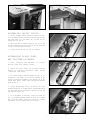
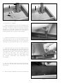
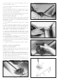
10. Assemble splitter (P) Fig. 22, inside the splitter
mounting bracket as shown. Push splitter (P) down as far
as possible, making certain bottom edge (T) of splitter (P)
is parallel with table surface, and tighten screw (B).
B
P
11. Reassemble the saw blade (U) Fig. 22.
N
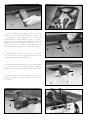
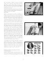
12. Using a straight edge (A) Fig. 23, and square (B) Fig.
24, align splitter (P) with the saw blade and table by
moving brackets (M) and (L) until the splitter (P) is in
perfect alignment with the blade and square with the
table. After alignment is made, tighten hex head screw
(N), and two screws (S) Fig. 24.
L
M
S
Fig. 24
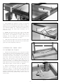
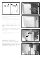
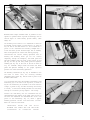
13. IMPORTANT: For certain cutting operations such as
dadoing and moulding where you are not cutting
completely through the workpiece, the blade guard and
splitter assembly cannot be used. Loosen screws (B) and
(V) Fig. 25. Lift up and swing blade guard and splitter
assembly to the rear of the saw.CAUTION: Always return
the blade guard and splitter assembly to its proper
operating position for normal thru-sawing operations.
V
B
BIESMEYER FENCE
A S S E M B LY
Fig. 25
ASSEMBLING GUIDE RAILS
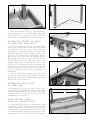
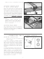
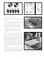
1. Assemble the front rail (A) Fig. 26, to front of saw
table using the two 3/8-16 x 11/4″ flat head Phillips screws
(B), 7/8″ flat washers, lockwashers and 3/8-16 hex nuts
supplied. Screws (B) are inserted through the two holes in
the front rail, as shown in Fig. 26, and through the two
through holes in the front of the saw table and fastened to
the table with the flat washers, lockwashers and hex nuts.
IMPORTA N T: Do not completely tighten front rail
mounting hardware at this time.
A
B
Fig. 26
9