1
00Template.book Page 105 Friday, January 2, 2004 2:55 PM
ACH550 User's Manual
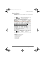
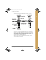
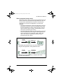
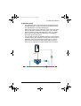
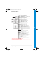
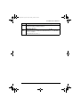
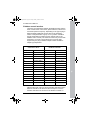
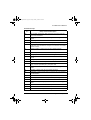
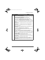
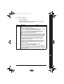
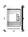
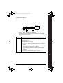
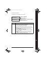
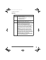
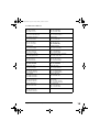
Floating point
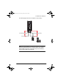
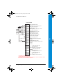
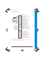
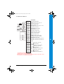
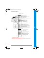
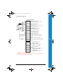
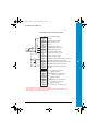
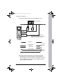
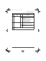
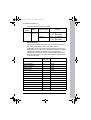
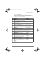
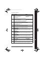
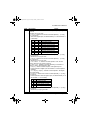
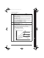
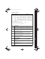
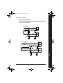
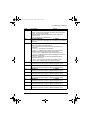
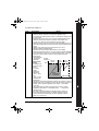
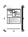
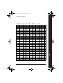
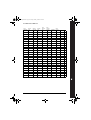
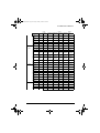
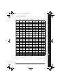
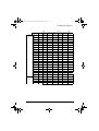
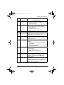
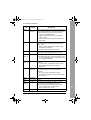
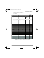
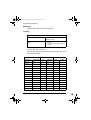
Signal cable shield (screen)
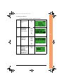
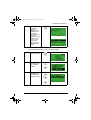
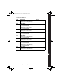
1
SCR
2
AI1
3
AGND
4
10 V
Reference voltage 10 VDC
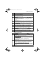
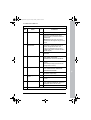
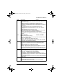
5
AI2
Not used
Not used
Analog input circuit common
6
AGND Analog input circuit common
7
AO1
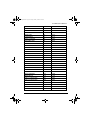
Output frequency: 0(4)...20 mA
8
AO2
Output current: 0(4)...20 mA
9
AGND Analog output circuit common
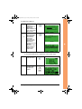
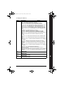
10
24 V
Auxiliary voltage output + 24 V
11
GND
Common for DI return signals
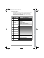
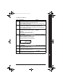
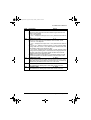
12 DCOM Digital input common for all
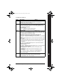
13
DI1
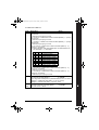
Start/Stop: Activation starts the drive
14
DI2
Run enable: Deactivation stops the drive**
15
DI3
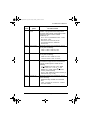
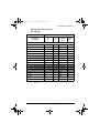
Constant Speed 1: (Par 1202)*
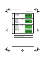
16
DI4
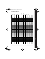
Start enable 1:Deactivation stops the drive**
17
DI5
Reference up: Activation increases the reference
18
DI6
Reference down: Activation decreases the reference
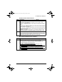
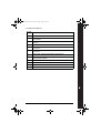
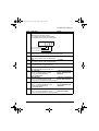
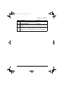
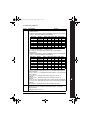
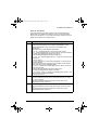
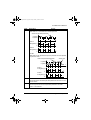
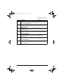
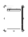
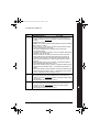
19 RO1C
20 RO1A
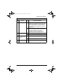
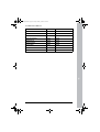
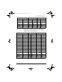
Relay output 1 (Par 1401)
21
RO1B
Started=> 19 connected to 21
22
RO2C
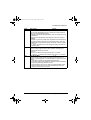
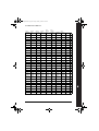
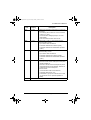
Relay output 2 (Par 1402)
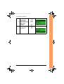
23
RO2A
Default operation
24
RO2B
Running=> 22 connected to 24
Default operation
25
RO3C
Relay output 3 (Par 1403)
26
RO3A
Default operation
27
RO3B
Fault (-1)=> 25 connected to 27
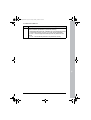
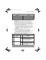
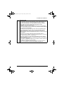
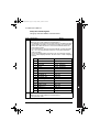
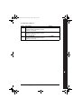
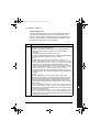
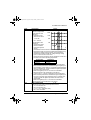
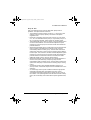
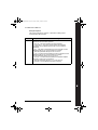
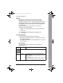
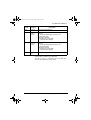
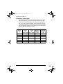
*Not available if PID is active
**Disable/enable with parameters 1601 and 1608
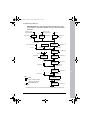
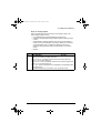
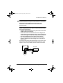
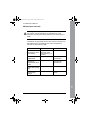
Note! Drive starts only if possible protection functions (Run enable or Start enable 1 and 2)
are activated from I/O or disabled with parameters.
Wiring and applications
105