1
00Template.book Page 392 Friday, January 2, 2004 2:55 PM
ACH550 User's Manual
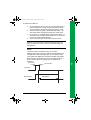
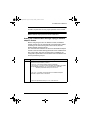
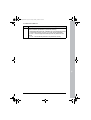
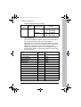
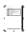
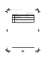
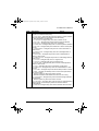
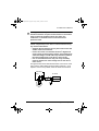
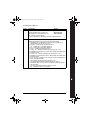
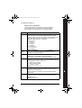
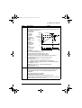
Note! For safety reasons the fault relay signals a “fault” when
the ACH550 is powered down.
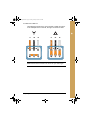
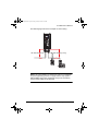
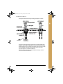
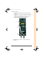
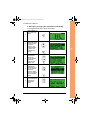
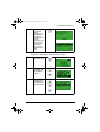
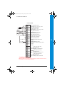
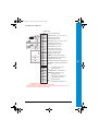
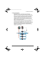
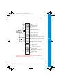
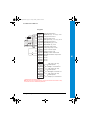
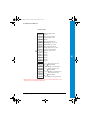
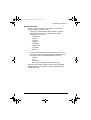
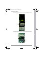
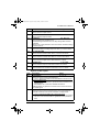
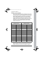
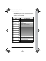
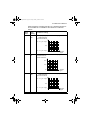
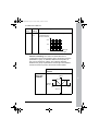
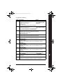
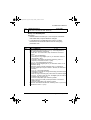
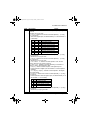
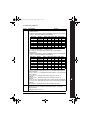
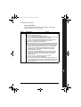
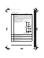
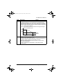
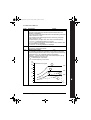
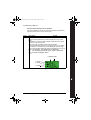
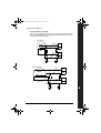
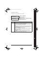
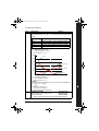
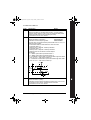
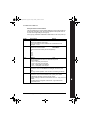
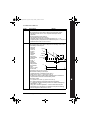
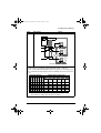
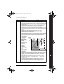
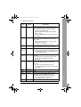
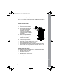
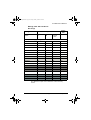
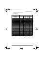
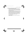
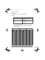
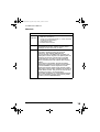
You can wire the digital input terminals in either a PNP or NPN
configuration.
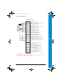
PNP connection (source)
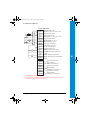
X1
10 +24V
11 GND
12 DCOM
13 DI1
14 DI2
15 DI3
16 DI4
17 DI5
18 DI6
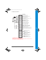
NPN connection (sink)
X1
10 +24V
11 GND
12 DCOM
13 DI1
14 DI2
15 DI3
16 DI4
17 DI5
18 DI6
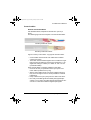
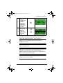
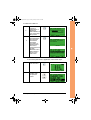
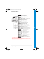
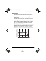
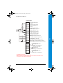
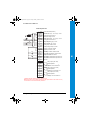
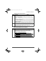
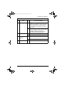
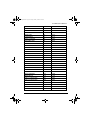
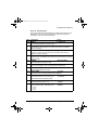
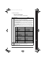
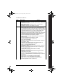
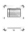
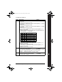
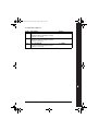
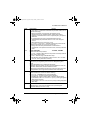
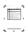
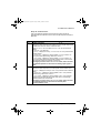
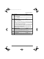
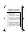
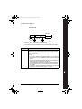
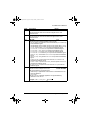
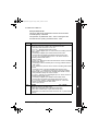
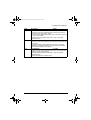
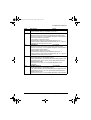
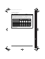
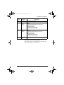
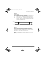
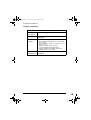
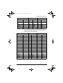
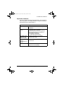
Communications
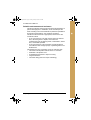
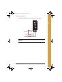
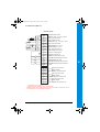
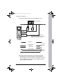
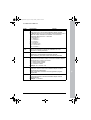
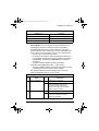
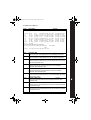
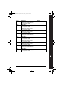
Terminals 28…32 are for RS485 modbus communications. Use
shielded cables.
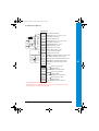
X1
Identification
28
Screen
29
B
30
A
31
AGND
32
Screen
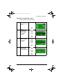
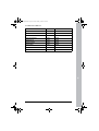
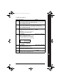
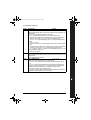
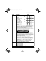
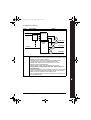
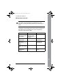
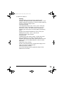
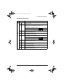
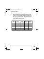
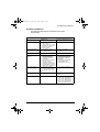
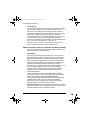
Hardware description1
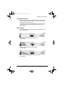
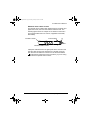
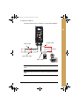
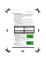
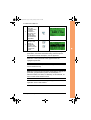
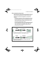
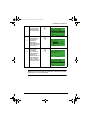
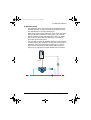
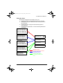
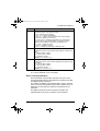
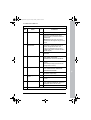
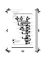
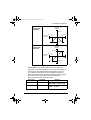
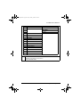
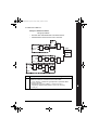
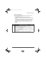
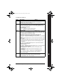
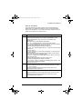
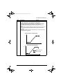
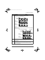
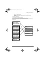
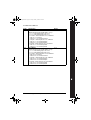
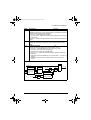
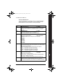
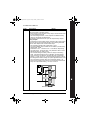
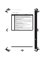
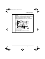
RS485 Multidrop application
Other Modbus devices
28 SCR
SCR
29 B
B
30 A
A
31 AGND
GND
32 SCR
B
A
GND
SCR
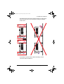
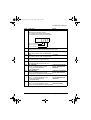
RS485 interface
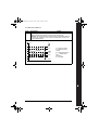
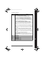
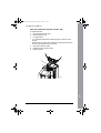
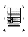
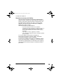
J2 J5
J2 J5
ON ON
ON ON
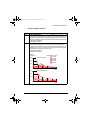
off position
on position
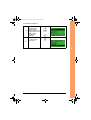
Bus termination
1 For functional descriptions, see section "Wiring and
applications" and section "Parameter listing and descriptions".
392
Appendix and available options