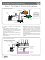
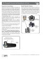
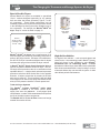
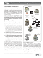
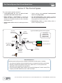
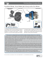
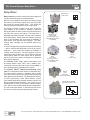
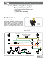
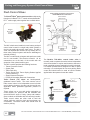
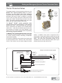
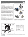
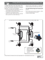
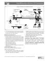
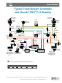
1
DRIVING SAFER DOESN’T HAPPEN BY ACCIDENT. Our nation’s roadways are increasingly busy, and the need has never been greater for solutions to help commercial vehicle drivers respond to the situations they encounter every day – especially in today’s CSA (Compliance, Safety, Accountability) environment. Bendix is leading the way to improved highway safety with an ever-increasing portfolio of road-tested, advanced commercial vehicle technologies that are affordable and effective. We offer robust active and supportive safety technologies that help fleets: » reduce collisions » increase stopping power » strengthen driver performance with actionable data Our solutions are driving in a new era of safety. Learn more. Call 1.800.247.2725 or visit bendix.com today. Follow us on Twitter @Bendix_CVS. ©Bendix Commercial Vehicle Systems LLC, a member of the Knorr-Bremse Group. All Rights Reserved. 06/12 » improve stability The Air Brake Handbook For more information, visit www.bendix.com or www.foundationbrakes.com • 1-800-AIR-BRAKE (1-800-247-2725) 1 Device Index Alphabetic Device Index AutoVue® by Bendix CVS Lane Departure Warning (LDW) System . . . . . 50 Bendix® A-18™ Controller Assy . . . . . . . . . . . . . . 44 Bendix® ACom® Diagnostic Software . . . . . . . . . . . 48 Bendix® Brand Actuators. . . . . . . . . . . . . . . . . . 20 Bendix® AD-2®, AD-9®, AD-9si™, AD-IP® Air Dryers . . . . 13 Bendix® AD-IS® Air Dryer Module . . . . . . . . . . . . . 13 Bendix® AD-SP® Air Dryer . . . . . . . . . . . . . . . . . 15 Bendix® AF-3™ In-line Air Filter. . . . . . . . . . . . . . . 15 Bendix® Brand Air Disc Brakes . . . . . . . . . . . . . . 23 Bendix® ASA-5® Automatic Slack Adjuster . . . . . . . . 24 Bendix® BA-921®, BA-922® Air Compressors . . . . . . 10-11 Bendix® BASIC™ Test Kit. . . . . . . . . . . . . . . . . . .11 Bendix® BP-R1® Bobtail Proportioning Relay Valve . . . . 26 Bendix® BVA-85™ Brake Valve Actuator . . . . . . . . . . 30 Bendix® BX-2150™ Air Compressor . . . . . . . . . . . . 10 Bendix® Converter Dolly Brakes . . . . . . . . . . . . . . 36 Bendix® Cyclone DuraDrain® Trailer Water Separator . . . 15 Bendix® D-2® Governor . . . . . . . . . . . . . . . . . . 12 Bendix® DC-4® Double Check Valve. . . . . . . . . . . . 17 Bendix® Dryer Reservoir Module . . . . . . . . . . . . . 14 Bendix® DS-2™ Double Check Valve & Stop Light Switch . 17 Bendix® DuraFlo 596™ Air Compressor . . . . . . . . . 10-11 Bendix® E-10™, E-10P™ Brake Valve . . . . . . . . . . . 19 Bendix® E-10PR™ Retarder Control Brake Valve . . . . . 19 Bendix® E-6® , E-7™, E-8P® Brake Valves . . . . . . . . . 19 Bendix® EC-30™, EC-60™ ABS/ATC Controller . . . . . . 39 Bendix® ESP® Functionality . . . . . . . . . . . . . . . . 41 Bendix® EverFlow® Module . . . . . . . . . . . . . . . . 14 Bendix® Inlet Check Valve . . . . . . . . . . . . . . . . . 12 Bendix® Inlet Regulating Valve. . . . . . . . . . . . . . . 12 Bendix® LP-3™ Low Pressure Indicator . . . . . . . . . . 16 Bendix® LQ-4™ Ratio Valve, LQ-2™, LQ-5™ Limiting Valves 25 Bendix® M-32™ and M-32QR™ Modulators. . . . . . . . . 38 Bendix® MV-3® Dash Control Module . . . . . . . . . . . 32 Bendix® PP-1® and PP-3™ Valves . . . . . . . . . . . . . 27 Bendix® PP-5™ Push-Pull Control Valve . . . . . . . . . . 30 Bendix® PP-7™, PP-8™ Control Valves . . . . . . . . . . . 27 Bendix® PP-DC® Park Control Valve . . . . . . . . . . . 31 Bendix® PR-2™, PR-4™ Pressure Protection Valves . . . . 17 Bendix® PR-3™ Reservoir Control Valve . . . . . . . . . . 37 Bendix® PuraGuard® QC™ Oil Coalescing Filter . . . . . . 15 Bendix® QR-1®, QR-1C® , QR-L™, QRN™ Quick Release Valves . . . . . . . . . . . . . . . 25 Bendix® R-12DC® Relay Valve . . . . . . . . . . . . . . 26 Bendix® R-12P™ Relay Valve . . . . . . . . . . . . . . 26-36 Bendix® R-12®, R-14®, R-6™ Relay Valves . . . . . . . . . 26 Bendix® R-7™ Modulating Valve . . . . . . . . . . . . . . 25 Bendix® R-8P™ Relay Valve . . . . . . . . . . . . . . . . 26 Bendix® RD-3™ Control Valve . . . . . . . . . . . . . . . 30 Bendix® RDU™ (Remote Diagnostic Unit) . . . . . . . . . 47 Bendix® RE-6NC™ Relay Emergency Valve . . . . . . . . 37 Bendix® Reservoirs . . . . . . . . . . . . . . . . . . . . 16 Bendix® RV-1™, RV-3™ Pressure Reducing Valve . . . . . 17 Bendix® Foundation Drum Brakes . . . . . . . . . . . . . 22 Bendix® SC-3™Single Check Valve . . . . . . . . . . . . 16 Bendix® SC-PR™ Valve . . . . . . . . . . . . . . . . . . 15 Bendix® SL-4™ and SL-5™ Stop Lamp Switches . . . . . . 29 Bendix® Spring Brake Actuators . . . . . . . . . . . . . . 20 Bendix® SR-2™, SR-4™, SR-5™ Spring Brake Valve . . . . 34 Bendix® SRC-7000™ Trailer Spring Brake Valve . . . . . 34-35 Bendix® ST-1™, ST-3™ and ST-4™, Safety Valves . . . . . 16 Bendix® SV-1™ Synchro Valve . . . . . . . . . . . . . . . 30 Bendix® SV-4™ Synchro Valve . . . . . . . . . . . . . 30, 36 Bendix® System-Guard® Trailer Air Dryer . . . . . . . 15, 61 Bendix® TABS-6, TABS-6 Advanced Trailer ABS . . . . . 45 Bendix® TABS-6 Advanced MC Trailer ABS . . . . . . . . 46 Bendix® TC-2™, TC-6™, TCS-9000™ Trailer Control Valves 32 Bendix® TE-1™ Trailer Emergency Stop Light . . . . . . . 35 Bendix® TP-3®, TP-3DC™, TP-5™ Tractor Protection Valves . . . . . . . . . 33 ® Bendix TR-3™ Valve. . . . . . . . . . . . . . . . . . . . 30 Bendix® Trailer Control (TC) Valves . . . . . . . . . . . . 32 Bendix® TRDU™ (Trailer Remote Diagnostic Unit) . . . . . 47 Bendix® Tu-Flo® 400, 500, 501, 550, 700, and 750 Air Compressors . . . . . . . . . . . . 10-11 Bendix® TW-1™, TW-2™, TW-3™ Control Valves . . . . . . 29 Bendix® TW-11™, TW-12™ Valve . . . . . . . . . . . . . . 29 Bendix® Versajust® . . . . . . . . . . . . . . . . . . . . . 24 Bendix® Wingman® Advanced . . . . . . . . . . . . . . . 49 Bendix® WS-24™ Wheel Speed Sensors . . . . . . . . . 38 Bendix® Yaw Stability . . . . . . . . . . . . . . . . . . . 41 SmarTire® Tire Pressure Monitoring System (TPMS) by Bendix CVS . . . . . . . . . . . . . . . . . . 50 Bendix Commercial Vehicle Systems LLC and Bendix Spicer Foundation Brake LLC now provide both on-line and in-person Bendix Brake Training Schools. • The Bendix On-line Brake School is your complete resource for web-based technical training. Keep your skills sharp with a comprehensive menu of ever-evolving instructional videos and interactive modules. • The In-Person Bendix Brake Training School is conducted by the veteran ASE-certified Bendix team, this allinclusive course of classroom lectures is available at locations around the country. • To enroll, visit www.bendix.com, click on the "Services & Support" tab, select "Brake School" from the menu on the left side of the page, and then choose the type of school you wish to participate in. 2 For more information, visit www.bendix.com or www.foundationbrakes.com • 1-800-AIR-BRAKE (1-800-247-2725) Handbook Section Index How to use the Air Brake Handbook This twelve-section handbook provides an introduction to the use and operation of Bendix air brake systems and devices. Components are introduced and shown with typical system diagrams to depict where they are used. As new components are introduced and their function explained, they gradually build up to a complete functioning air brake system reflected in the schematics at the close of this handbook. Partial system-drawings, displayed throughout the manual, assist in explaining the use of the components. See section 12 for examples of vehicle system schematics. Contents Air Brake Handbook Section Page No. Index and Precautions Air Brake Handbook Section Page No. Section 4: Tractor Parking,Trailer Charging/ Parking and Emergency Systems Device Index 2 Handbook Section Index 3 Tractor/Trailer Parking and Emergency Systems 31 General Precautions 4 Park Control Valves 31 72-76 Dash Control Valves 32 Tractor Protection Valves 33 Trailer Spring Brake Valves 34-35 Glossary Section 1: Introduction An Introduction 6-7 Section 2: The Charging, Air Treatment and Storage System The Charging, Air Treatment and Storage System Compressors 8 9-11 Governors, Etc. Air Dryers Section 5: Convertor Dolly Brakes Trailer/Converter Dolly Brakes Section 6: Antilock Braking System 12 Antilock Braking Systems: Components 38 13-15 Truck and Tractor ABS Operation; ATC 39-40 Reservoirs, Etc. 16 Advanced ABS Misc. Components 17 Advanced ABS Operation and Features Section 3: The Control System 41 42-43 Trailer ABS Components and Operation 44 45 46 The Control System: Dual Circuit Brake Valves 19 PLC, Troubleshooting Actuators 20 Advanced Trailer ABS Operation and Features Foundation Brakes: Drum Brakes (aka S-Cam) 21 Troubleshooting ABS Foundation Drum Brakes 22 Air Disc Brakes 23 Slack Adjusters 24 Quick Release, Ratio & Modulating Valves 25 Relay Valves 26 Push-Pull Control Valves 27 Spring Brake Valves 28 Lever-Operated Control Valves 29 Downloading and Ordering Literature 30 Contacting Bendix Additional Control Valves 36-37 47-48 Section 7: Additional Systems and Components Additional Systems and Components 49-50 Section 8: The Fundamentals of Air Braking Air Brake System Fundamentals 51-62 Section 9: Air Brake System Troubleshooting Test Air Brake System Troubleshooting Tests 63-68 Section 10: Bendix Literature and Contact Information 69-70 69 Section 11: About Bendix About Bendix Commercial Vehicle Systems LLC 71 Section 12: Typical Air Brake System Schematics DIN symbols are used in this handbook. Examples of Air Brake System Schematics For more information, visit www.bendix.com or www.foundationbrakes.com • 1-800-AIR-BRAKE (1-800-247-2725) 81-89 3 General Precautions IMPORTANT The systems presented in this manual are intended for illustrative purposes only and are not intended to be used for actual vehicle piping. Air Brake System General Precautions GENERAL SAFETY GUIDELINES WARNING! PLEASE READ AND FOLLOW THESE INSTRUCTIONS TO AVOID PERSONAL INJURY OR DEATH: When working on or around a vehicle, the following guidelines should be observed AT ALL TIMES: ▲ Park the vehicle on a level surface, apply the parking brakes and always block the wheels. Always wear personal protection equipment. ▲ Stop the engine and remove the ignition key when working under or around the vehicle. When working in the engine compartment, the engine should be shut off and the ignition key should be removed. Where circumstances require that the engine be in operation, EXTREME CAUTION should be used to prevent personal injury resulting from contact with moving, rotating, leaking, heated or electrically-charged components. ▲ Do not attempt to install, remove, disassemble or assemble a component until you have read, and thoroughly understand, the recommended procedures. Use only the proper tools and observe all precautions pertaining to use of those tools. ▲ If the work is being performed on the vehicle’s air brake system, or any auxiliary pressurized air systems, make certain to drain the air pressure from all reservoirs before beginning ANY work on the vehicle. If the vehicle is equipped with a Bendix® AD-IS® air dryer system, a Bendix® DRM™ dryer reservoir module, or a Bendix® AD-9si™ air dryer, be sure to drain the purge reservoir. ▲ F o l l o w i n g t h e v e h i c l e m a n u f a c t u r e r ’s recommended procedures, deactivate the electrical system in a manner that safely removes all electrical power from the vehicle. ▲ Never exceed manufacturer’s recommended pressures. ▲ Never connect or disconnect a hose or line containing pressure; it may whip. Never remove a component or plug unless you are certain all system pressure has been depleted. ▲ Use only genuine Bendix® brand replacement parts, components and kits. Replacement hardware, tubing, hose, fittings, etc. must be of equivalent size, type and strength as original equipment and be designed specifically for such applications and systems. ▲ Components with stripped threads or damaged parts should be replaced rather than repaired. Do not attempt repairs requiring machining or welding unless specifically stated and approved by the vehicle and component manufacturer. ▲ Prior to returning the vehicle to service, make certain all components and systems are restored to their proper operating condition. ▲ For vehicles with Automatic Traction Control (ATC), the ATC function must be disabled (ATC indicator lamp should be ON) prior to performing any vehicle maintenance where one or more wheels on a drive axle are lifted off the ground and moving. ▲ The power MUST be temporarily disconnected from the radar sensor whenever any tests USING A DYNAMOMETER are conducted on a Bendix® Wingman® Advanced™-equipped vehicle. ▲ You should consult the vehicle manufacturer's operating and service manuals, and any related literature, in conjunction with the Guidelines above. 4 For more information, visit www.bendix.com or www.foundationbrakes.com • 1-800-AIR-BRAKE (1-800-247-2725) :KHQ<RX:DQW,W:KHUH<RX1HHG,WZZZEUDNHVFKRROFRP The Bendix Online Brake School is your complete resource for web-based technical training, straight from the experts. Keep your skills sharp with a comprehensive menu of ever-evolving instructional videos and interactive modules. Home to e-training on a full range of Bendix products and industry hot topics, www.brake-school.com offers courses on: • Air Dryers and Compressors • Valves • Disc and Drum Brakes • Vehicle Stability • Electronics • Air Brake System training and more! Visit www.brake-school.com, register for your secure account and take the course(s) that you need. Each course is accompanied by a brief quiz to test your knowledge. Put yourself to the test. Bendix Online Brake School... where you need it, when you need it, and on the topics that matter most to advancing your skill set. BW2948 © 2013 Bendix Commercial Vehicle Systems LLC, a member of the Knorr-Bremse Group • 03/13 • All Rights Reserved For more information, visit www.bendix.com or www.foundationbrakes.com • 1-800-AIR-BRAKE (1-800-247-2725) 5 Introduction Section 1: An Introduction Air Supply The vehicle’s compressor takes in filtered air — either at atmospheric pressure from the outside or already at an increased pressure from an engine turbocharger — and compresses it. The compressed air is delivered to the air dryer where water and a small amount of oil is removed. The air then travels into the air reservoirs (“air tanks”). It is typically delivered to a rear brake system reservoir and a front brake system reservoir, as well as any attached trailer reservoirs. For each system, the air pressurizes the reservoir and the air hoses all the way to the next control valve, where the air pressure remains, ready to use. A vehicle may use compressed air for many tasks. Some examples are: to provide force for braking, to deliver air to a particular component, to off-load bulk goods, etc. Normal Braking When the driver applies the foot brake, a plunger within the foot brake valve moves, opening channels within the valve that allow the air pressure waiting there to pass through and be delivered to the rear and front brake systems. The pressure quickly increases in the brake chambers and applies force to the push rod, transferring the force to the air disc brake (or via a slack adjuster, to a foundation drum brake). (See page 21 for more about foundation brakes, and government-mandated stopping distances.) Frictional forces slow the wheels and the vehicle comes to a stop. When the brakes are released, the air in the brake chambers is quickly released, enabling the vehicle to drive away. Vehicle Parking Vehicles are parked using powerful springs, which are part of the spring brake assembly, to engage the brakes and hold the vehicle in position. When the driver prepares to move away and releases the parking brake, the spring force is countered by the introduction of air pressure. An anti-compounding valve in the system design helps prevent the application of both the spring and service brakes together. 6 Emergency Braking In emergency situations where system air pressure is reduced or lost, government regulations require vehicles to meet specified stopping distances. As an example, some straight truck system designs use modulated parking-brake applications to bring the vehicle to a stop. Electronically-Controlled Braking The following systems enhance the air brake system by adding electronic sensors and controllers to modify the vehicle’s braking characteristics. • Antilock Braking Systems (ABS) Most commercial vehicles use electronic Antilock Braking Systems (ABS) to help improve braking when excessive wheel slip, or wheel lock-up, is detected. Bendix® Electronic Control Units (ECUs) use patented technology to monitor wheel speeds (on all wheels equipped with speed sensors) and use ABS modulator valves to adjust, or pulse, the braking force being applied. These valves operate multiple times per second during an ABS event. ABS typically improves stability and steerability, and also helps reduce stopping distances on most surfaces. In addition to the ABS features above, some advanced ECUs have a drag torque control feature which helps reduce drive-axle wheel slip (due to driveline inertia) by communicating with the engine’s controller and increasing the engine torque. Automatic Traction Control In addition to the ABS function, many Bendix ECU models provide an Automatic Traction Control (ATC) feature which can help improve vehicle stability and traction during vehicle acceleration at low speeds. • Hill Start Feature For vehicles with the optional Bendix hill start feature (often referred to as Hill Start Assist/Assistance or HSA), the system interfaces between the transmission and the braking system to help the driver prevent the vehicle from rolling downhill when moving up a steep incline from a stationary position. For more information, visit www.bendix.com or www.foundationbrakes.com • 1-800-AIR-BRAKE (1-800-247-2725) Introduction, continued Electronically-Controlled Braking (continued) • Bendix® Electronic Stability Program/ Full Stability Program The ESP®* functionality of the Bendix advanced ABS system responds to a wide range of low- to highfriction surface scenarios including rollover, jackknife and loss-of-control. It is the recommended system for all power vehicles and especially critical for tractors pulling trailers. In the case of vehicle slide (over-steer or under-steer situations), the system will reduce the throttle and then brake one or more of the “four corners of vehicle” (in addition to potentially braking the trailer), thus applying a counter-force to better align the vehicle with an appropriate path of travel. In the case of a potential roll event, the system reduces the throttle and quickly applies the brakes to slow the vehicle combination below the threshold. Bendix ® Wingman® Advanced™ — A Collision Mitigation Technology The Bendix® Wingman® Advanced™ system — which uses a radar sensor mounted on the front of the vehicle — is an integrated combination of three features: adaptive cruise control with braking; alerts (several different types); and collision mitigation technology. The adaptive cruise control with braking feature is an additional upgrade of ordinary cruise control. When using cruise control, the Wingman Advanced system will maintain the set vehicle speed, and will also intervene, as needed, to help maintain a set following distance behind a detected forward vehicle. The Bendix Wingman Advanced system also assists by giving audible and visual alerts, whether or not cruise control is on. The collision mitigation technology feature is designed to be ready to react to the presence of moving vehicles in front of the vehicle (whether or not cruise control is set). AutoVue® Lane Departure Warning (LDW) by Bendix CVS The AutoVue® Lane Departure Warning (LDW) system detects when a vehicle drifts across a lane marking. When this occurs and the turn signal is not activated, the unit automatically emits a distinctive “rumble strip” or other warning (using speakers or – if a non-audible warning is preferred – a vibrating seat), alerting the driver to make a correction. The AutoVue LDW system utilizes a camera with a 60-degree field of view that tracks visible lane markings, including both solid and dashed shoulder lines, centerlines, and lines between lanes – even if they are heavily faded. It works effectively both day and night and in most weather conditions, like rain or fog, where visibility is limited. Even in snowy conditions, if the driver can see the lane markings, the AutoVue LDW system can as well. SmarTire® Tire Pressure Monitoring System (TPMS) by Bendix CVS Bendix offers a wireless approach to tire pressure monitoring. Using a sensor/transmitter mounted securely inside each tire, a wireless receiver and a dashmounted display, the SmartWave ® TPMS system actively measures the air pressure and temperature within the tires. This information is then sent wirelessly to a receiver mounted on the vehicle, or a hand-held display, and alerts the driver of a loss of air pressure or dangerously high tire temperature. Driving Vehicles Equipped with Bendix® Advanced Technologies The driver is always responsible for the control and safe operation of the vehicle at all times. Even with Bendix® advanced technologies such as the Bendix® ESP® stability system and Bendix® Wingman® Advanced™, the need for a skilled, alert professional driver, reacting appropriately and in a timely manner, and using safe driving practices, remains the most important factor in road safety. *ESP is a registered trademark of Daimler and is used by BCVS under license. For more information, visit www.bendix.com or www.foundationbrakes.com • 1-800-AIR-BRAKE (1-800-247-2725) 7 The Charging, Air Treatment and Storage System Section 2: The Charging, Air Treatment and Storage System Traditional Air Charging System To Front Axle To Rear Axle Low Pressure Indicator Note: A threereservoir system is shown here. See below for a system using an integrated air dryer/reservoir. Air Dryer Safety Valve Check Valves Governor Purge Valve Safety Valve Primary (Rear Axle) Reservoir Air Compressor Supply Reservoir Drain Valve The charging, air treatment and storage system consists of: • An air compressor, to pressurize the system; • A governor, to control when the compressor needs to build, or stop building, air for the system and also to control the air dryer purge cycle; • An air dryer, to remove water and oil droplets from the air; • Reservoirs (or “air tanks”) to store air to be used for vehicle braking, etc.; • Safety valves to protect against excessive pressure in the system in the event that a charging system component malfunction occurs (e.g. a line blockage); • Single check valves to maintain a one-way flow of air into the reservoirs. This arrangement protects the contents from being drained in the event of an upstream loss of pressure; and • Low pressure indicators to alert the driver whenever a reservoir has less than a pre-set amount of air available. Integrated Air Dryer/Reservoir System To Front Axle Integrated Air Dryer Housing Also Includes: Safety Valve; Check Valve; Purge Valve; Delivery Check Valves Governor Safety Valve Purge Reservoir Secondary (Front Axle) Reservoir Bendix ® PuraGuard® QC™ Filter Air Compressor 8 To Rear Axle Primary (Rear Axle) Reservoir To Vehicle Accessories Sensitive to Oil Carryover To Vehicle Accessories For more information, visit www.bendix.com or www.foundationbrakes.com • 1-800-AIR-BRAKE (1-800-247-2725) The Charging, Air Treatment and Storage System: Compressors Bendix Air Compressors The air compressor is the source of energy for the air brake system. Usually driven by the vehicle engine, the air compressor builds the air pressure for the air brake system. The air compressor is typically cooled by the engine coolant system and lubricated by the engine oil supply. (Certain models have self-lubricated and/or air-cooled versions available.) Note: Air compressor shafts can rotate in either direction. The vehicle’s compressor draws in filtered air — either naturally aspirated (at atmospheric pressure) from the outside (or already at an increased pressure from the engine turbocharger where permitted) — and compresses it until system pressure is achieved. To function, the brake system needs a supply of compressed air within a preset maximum and minimum. The governor (along with a synchro valve for certain Bendix® air compressors) monitors the air pressure in the supply reservoir and monitors when the compressor needs to pump air into the air system (also known as the “air build cycle” — where the compressor is “running loaded”). When the system has sufficient air, the compressor can simply turn over without building pressure (“running unloaded”). It also monitors when the air pressure becomes greater than that of the preset “cut-out”, the governor controls the unloader mechanism of the compressor, stops the compressor from building air and causes the air dryer to purge. As the service reservoir air pressure drops to the “cut-in” setting of the governor, the governor returns the compressor back to building air and cycles the air dryer back to air drying mode. As the atmospheric air is compressed, all the water vapor originally in the air is carried along into the air system (as well as a small amount of the compressor lubricating oil) as vapor. The duty cycle is the ratio of time the compressor spends building air, relative to the total engine running time. Air compressors are designed to build air (run “loaded”) up to 25% of the time. Higher duty cycles cause conditions (such as higher compressor head temperatures) that may adversely affect air brake charging system performance. These conditions may require additional maintenance due to a higher amount of oil vapor droplets being passed along into the air brake system. Factors that add to the duty cycle are: air suspension, additional air accessories, use of an undersized compressor, frequent stops, excessive Safety Valve Air Dryer — Typically with a Bendix ® PuraGuard® Oil Coalescing Filter Discharge Line Purge Valve Safety Valve Governor Air Compressor Supply Reservoir Air Treatment System Drain Valve leakage from fittings, connections, lines, chambers or valves, etc. See page 11 for compressor maintenance and usage guidelines. Use the Bendix® BASIC™ test (p/n 5013711) where the amount of oil present in the air brake system is suspected to be above normal. The discharge line allows the air, water vapor and oil vapor mixture to cool between the compressor and air dryer. The typical size of a vehicle’s discharge line, (see table on page 10) assumes a compressor with a normal (less than 25%) duty cycle, operating in a temperate climate. See Bendix and/or the vehicle or air dryer manufacturer guidelines as needed. Air dryer inlet temperatures play a key role in air system cleanliness and air dryer performance. When the temperature of the compressed air that enters the air dryer is within the normal range, the air dryer can remove most of the charging system oil. If the temperature of the compressed air is above the normal range, oil (as oilvapor) is able to pass through the air dryer and into the air system. Larger diameter discharge lines and/or longer discharge line lengths can help reduce the temperature. The discharge line must maintain a constant slope down from the compressor to the air dryer inlet fitting to avoid low points where ice may form and block the flow. If, instead, ice blockages occur at the air dryer inlet, insulation may be added here — or if the inlet fitting is a typical 90-degree fitting — it may be changed to a straight, or 45-degree fitting, to prevent moisture buildup and freezing. For more information on how to help prevent discharge line freeze-ups, see Bendix Bulletins TCH-008-021 and TCH-008-022. Conversely, shorter discharge line lengths (or insulation) may be required in extreme cold climates to maintain proper dryer operation. For more information, visit www.bendix.com or www.foundationbrakes.com • 1-800-AIR-BRAKE (1-800-247-2725) 9 The Charging, Air Treatment and Storage System: Compressors Bendix® SingleCylinder Compressors Bendix® Two-Cylinder Compressors Tu-Flo ® 550 Air Compressor or Tu-Flo ® 750 Air Compressor (exterior view is the same.) BA-921® Air Compressor BA-922® Air Compressor (shown) or DuraFlo 596™ Air Compressor (exterior view is very similar.) BX-2150™ Air Compressor Tu-Flo ® 700 Air Compressor Tu-Flo ® 501 Air Compressor Tu-Flo ® 400 Air Compressor Tu-Flo ® 500 Air Compressor Bendix® Four-Cylinder Compressors Compressor Comparison by Displacement n? io pt to le in o r- ? rb ai ble Tu r / ila a e at av W d Is ole elf ble? / s ila co ne va s gi a er En ted lind Is ica Cy br FM lu tC M en RP em 0 ac 25 pl 1 is at D Tu-Flo® 400 Compressor 7.25 2 Both Both Y Y** BX-2150™ Compressor 9.5 1 Eng. Water Tu-Flo® 500 Compressor 12 2 Eng. Water Y Tu-Flo® 501 Compressor 12 2 Both Both Y Tu-Flo® 550 Compressor 13.2 2 Eng. Water Y Tu-Flo® 700 Compressor 15.5 2 Eng. Water Y BA-921® Compressor 15.8 1 Eng. Water Y** Tu-Flo® 750 Compressor 16.5 2 Eng. Water Y 24 4 Both Both Y N Tu-Flo® 1000 Compressor* DuraFlo 596™ Compressor BA-922® Compressor Tu-Flo® 1400 Compressor* 27 2 Eng. Water 31.6 2 Eng. Water N 32 4 Eng. Water Y*** Tu-Flo ® 1000 Air Compressor Tu-Flo ® 1400 Air Compressor *Special use (e.g. Tank trailer pump-off) **Uses Inlet Check Valve ***Uses an Inlet Regulating Valve For compressor Service Data Sheet downloads, visit the document library on www.bendix.com. To order paper copies, visit the Literature Center at the same site. 10 For more information, visit www.bendix.com or www.foundationbrakes.com • 1-800-AIR-BRAKE (1-800-247-2725) The Charging, Air Treatment and Storage System: Compressors 2 4 Discharge Line Length Maintenance Schedule and Usage Guidelines Air Dryer Maintenance Schedule Regularly scheduled maintenance is the single most important factor in maintaining the air brake charging system. Depending on the vehicle’s air use, the table below shows examples of compressors spec’d, and typical discharge line lengths and maintenance intervals. See your compressor and/or air dryer Service Data Sheet for more information. 1 Air Compressor Spec’d 3 Reservoir Draining High Air Use e.g. Double/triple trailer, open highway coach, (most) pick-up & delivery, yard or terminal jockey, off-highway, construction, loggers, concrete mixer, dump truck, fire truck. Medium Air Use Low Air Use e.g. Line haul single trailer without air suspension; air over hydraulic brakes. Compressor with less than 15% duty cycle (builds air pressure during 15% or less of the engine running time.) e.g. Line haul single trailer with air suspension, RV, school bus. Compressor with up to 25% duty cycle Compressor with less than 25% duty cycle Very High Air Use e.g. City transit bus, refuse, bulk unloaders, low boys, urban region coach, central tire inflation. Compressor with up to 25% duty cycle (builds air pressure during 25% or less of the engine running time.) (5 or less axles) (5 or less axles) (8 or less axles) Examples of Typical Compressors Spec’d : a (12 or less axles) Bendix Tu-Flo 750 air compressor ® ® Bendix BA-921 air compressor ® 1 ® Bendix Tu-Flo® 550 air compressor ® Bendix® BA-922® air compressor Bendix® DuraFlo 596™ air compressor 2 Discharge line: Discharge line: Discharge line: Discharge line: 6 ft. @ ½ in. Inner Diameter 9 ft. @ ½ in. Inner Diameter 12 ft. @ ½ in. Inner Diameter 15 ft. @ 5/8 in. Inner Diameter (oil carry-over control (oil carry-over control suggested (oil carry-over control suggested (oil carry-over control suggested suggested upgrade b: 9 ft. upgrade b: 12 ft. @ 5/8 in.) upgrade b: 15 ft. @ 5/8 in.) upgrade b: 15 ft. @ ¾ in.) @ 5/8 in.) 3 Drain Reservoirs Every Month to 90 Days 4 Replace Air Dryer Cartridge Every 3 Yearsc Oil Passing Concerns? Use the BASIC Test Kit: Bendix P/N 5013711 BASIC Test acceptable range: ≤ 3 oil units per month. a. Compressor and/or air dryer upgrades are recommended in cases where duty cycle is greater than the normal range (for the examples above). For certain vehicles/applications, where turbo-charged inlet air is used, a smaller size compressor may be permissible. b. To counter above normal temperatures at the air dryer inlet (and resultant oil-vapor passing upstream in the air system), replace the discharge line with either a larger diameter and/or longer length line. This helps reduce the temperature of the discharged air. If Drain Reservoirs Every Month Replace Every 2 Yearsc Replace Every Year c BASIC Test acceptable range: ≤ 5 oil units per month. sufficient cooling occurs, the oil-vapor condenses and can be removed by the air dryer. Discharge line upgrades are not covered under warranty. Note: To help prevent discharge line freeze-ups, shorter discharge line lengths, or insulation, may be required in cold climates. See Bendix Bulletins TCH-008-021 and TCH-008-022, for more information. c. With increased air demand, the air dryer cartridge needs to be replaced more often. For more information, visit www.bendix.com or www.foundationbrakes.com • 1-800-AIR-BRAKE (1-800-247-2725) 11 The Charging, Air Treatment and Storage System: Governors, Etc. Governors and Components The Governor monitors the air pressure in the supply reservoir and operates the compressor unloading mechanism to control whether or not the compressor builds air pressure. Exhaust Port Shown With Breather Valve Installed Bendix ® D-2A™ Governor Bendix ® D-2® Governor The Bendix® D-2® governor is an adjustable pistontype valve. It is available preset to a choice of pressure settings. Note: The pressure range between the cut-in and cut-out pressure is designed into the governor and is not adjustable. The D-2 governor may be directmounted to the compressor or remote-mounted as desired. Specialized governors are available for vehicles needing a governor adapted to abnormally high or low temperatures, as well as a “weatherproof” model. For example: • The Bendix® D-2A™ governor is a non-adjustable version of the D-2® governor. • The D-2®/SV-1™ governor module is a special combination device used with the Bendix® DuraFlo 596™ air compressor to provide the fast-rising unloader signal needed by this compressor. Safety Valves are used in an air brake system to protect against excessive air pressure build-up and to sound an audible alert. Safety valves are available in both adjustable (e.g. the Bendix® ST-1™ valve) and nonadjustable (e.g. Bendix® ST-3™, and ST-4™ valve) styles, in a variety of pressure settings, and for a variety of port sizes. Maximum service system air pressure allowed by government regulation is typically 150 psi. A variety of safety valve settings are used at different points in the charging and treatment system. Specifically designed for use in compressors, ST-4 safety valves are installed — in an extra compressor head discharge port, if available or in the discharge line near the compressor — to prevent compressor damage in the event of discharge line blockage. An Inlet Regulating Valve (or “IRV”) is typically used on multi-cylinder compressors which receive their input air supply from the pressurized side of the engine turbocharger. The IRV, which is generally mounted to the compressor inlet, is designed to regulate compressor inlet pressure to 10 psi or less. The outlet flange of the IRV can be mounted to all Bendix® Tu-Flo® compressors except the Tu-Flo 300 compressor. The IRV may not be used in conjunction with single cylinder compressors. 12 Bendix ® D-2®/SV-1™ Governor Module Bendix ® ST-1™, ST-3™ and ST-4™ Safety Valves Inlet Regulating Valve Inlet Check Valves Inlet Check Valves (or “ICV” valves) are used on naturally aspirated compressors to prevent oil mist from entering the inlet line during the unloaded cycle. The inlet check valve either mounts to the intake side of the compressor (and must be used in conjunction with an inlet valve stop or inlet adapter), or may be mounted remotely. Visit the Bendix website at www.bendix.com for more information, including the Advanced Compressor Troubleshooting Guide (BW1971) and compressor Service Data sheets. For more information, visit www.bendix.com or www.foundationbrakes.com • 1-800-AIR-BRAKE (1-800-247-2725) The Charging, Air Treatment and Storage System: Air Dryers Integrated Purge Reservoir The Bendix ® PuraGuard® Graphics and Medallion - Indicates the presence of a PuraGuard Oil Coalescing Cartridge Bendix ® AD-9 ® Air Dryer Bendix ® AD-9 ® Air Dryer Cartridge Bendix ® AD-IS® Air Dryer Module Bendix ® AD-IS® Air Dryer Governor Bendix ® AD-IP ® DI Air Dryer (“Drop-in” version) Bendix ® AD-IP ® Air Dryer Cartridge Feedback Line Bendix ® AD-9si™ Air Dryer Bendix ® AD-2®Air Dryer Special Discharge Port Fitting with Feedback Line Connection Air Dryers The air dryer is an in-line filtration system that removes both water vapor and oil droplets from the compressor discharge air after it leaves the compressor. This results in cleaner, drier air being supplied to the air brake system, and aids in the prevention of air line and component freeze-ups in winter weather. As the air passes into the air dryer, most of the oil droplets are removed by the oil separator. The air then moves through the desiccant material which removes most of the water vapor before the compressed air is passed to the air brake service (supply) reservoir. The oil droplets, and the water collected, are automatically purged at the dryer when the governor reaches its “cut-out” setting. For vehicles with accessories that are sensitive to small amounts of oil, Bendix® PuraGuard ® oil coalescing air dryers are used. Similar in appearance to standard air dryers (with different graphics and an added center medallion symbol), PuraGuard oil coalescing air dryer cartridges contain a coalescing media at the inlet of the desiccant bed that provides a high level of oil removal. clean dry ai r Air passes through the oil separator and then the desiccant material. Important! When servicing, note that standard Bendix® brand air dryers or air dryer cartridges may be serviced with Bendix PuraGuard oil coalescing air dryers or cartridges, however, Bendix PuraGuard oil coalescing air dryers or cartridges must only be serviced with like replacements. For more information, visit www.bendix.com or www.foundationbrakes.com • 1-800-AIR-BRAKE (1-800-247-2725) 13 The Charging, Air Treatment and Storage System: Air Dryers Purge Cycles, Purge Volume Bendix® EverFlow® Modules When the air pressure in the supply air tank reaches the required level, the governor makes the compressor stop building air and allows the air dryer’s “purge cycle” to begin. During the purge cycle, the desiccant material is regenerated (its ability to remove water is renewed) by a reversal of the saturation process. A small amount of dry air passes back through the desiccant material and the water that has been collected, as well as any oil droplets collected by the oil separator, are purged out through the base of the dryer. It is normal to see a small amount of oil around the purge valve. The Bendix® AD-2®, AD-9®, AD-9si™, and AD-IP® air dryers are designed with an internal storage (“purge volume”) of dry air for the purge cycle. “Extended Purge” air dryers — such as the Bendix® AD-IP EP air dryer — are designed with an extra amount of air storage internally that is used to assist in the purge cycle. Air dryer end covers are typically equipped with an integral (12- or 24-volt) heating element for winter operation. Integrated Air Dryer Modules Bendix® EverFlow ® air dryer modules are used for air dryer systems where a vehicle needs a continuous flow of air, such as for bulk unloaders and central tire inflation. As stated earlier, air dryers need to initiate a purge cycle periodically to refresh the moisture-removing desiccant material. Bendix EverFlow air dryer modules have two air dryers plumbed in parallel that take turns supplying air, resulting in a continuous, uninterrupted supply. Technology advances in the charging, treatment and storage, have resulted in the availability of integrated air supply systems. For example, the Bendix® Dryer Reservoir Module — featuring the Bendix® AD-IS® (Integrated Solution) air dryer — provides heavy vehicles with integrated purge and supply reservoirs, an air dryer, governor and a number of the charging valve components, including four pressure protection valves. Bendix ® EverFlow ® Module Bendix ® AD-IP ® EverFlow® Air Dryer Assembly Bendix ® AD-IS® EverFlow® Air Dryer Assembly Bendix ® AD-9 ® EverFlow® Air Dryer Assembly Bendix ® AD-IS® Air Dryer (This example features a Bendix ® PuraGuard® Oil Coalescing Cartridge) Reservoir Dryer Reservoir Module 14 For more information, visit www.bendix.com or www.foundationbrakes.com • 1-800-AIR-BRAKE (1-800-247-2725) The Charging, Air Treatment and Storage System: Air Dryers Special Use Air Dryers Several Bendix air dryers are available in specialized “Drop-in” versions designed especially for air systems that use either the Holset (Cummins) Type E, or QE, air compressor. These Holset compressors use an unloading system that requires that air pressure remain in the discharge line during the entire unloaded cycle of the compressor. For example, the Bendix® AD-IP® air dryer “Drop-in” version is shown on page 13. Bendix ® AD-SP ® Air Dryer (installation uses SC-PR™ valve) Bendix ® Cyclone DuraDrain® Trailer Water Separator Bendix ® AF-3™ In-line Air Filter Bendix ® SC-PR™ Valve Bendix® AD-SP® air dryers use a small amount of air from the supply and front axle (secondary) reservoirs to perform the purge function. Because of this difference, the AD-SP air dryer is smaller and lighter than air dryers that have their purge volume within the dryer canister. A Bendix ® SC-PR™ Single Check Protection Valve is used in conjunction with the AD-SP air dryer. The SCPR single check protection valve is a combination of two separate devices — a single check valve and a pressure protection valve that allows limited flow in the opposite direction. It helps to protect the air pressure in the front axle service reservoir. This is because it will only allow its air supply to be used to help purge the Bendix AD-SP air dryer if the pressure is above a certain preset level. Bendix ® PuraGuard® QC™ Oil Coalescing Filter High Air-Use Vehicles For high air-use vehicles — such as transit buses and refuse trucks — the technology used in Bendix® SystemGuard air dryers is also available by using Bendix® PuraGuard ® QC™ oil coalescing filters. Installed downstream of the air dryer, these filters use a replaceable filter element mounted within a sump housing to remove oil aerosols before they can enter the air system. A drain valve allows periodic maintenance. Trailer Air Dryer Systems The Bendix® Cyclone DuraDrain® trailer water separator is installed in the trailer control and/or supply lines near the gladhands. It self-purges liquid contaminates, contains solid contaminants and improves the life of the trailer system components. The Bendix® AF-3™ in-line air filter screens out foreign material from trailer air lines. For more information, visit www.bendix.com or www.foundationbrakes.com • 1-800-AIR-BRAKE (1-800-247-2725) 15 The Charging, Air Treatment and Storage System: Reservoirs, Etc. Reservoirs, Etc. Reservoirs (or “air tanks”) serve the air brake system as a storage tank for compressed air. The reservoir size is selected by the vehicle manufacturer to provide an adequate amount of air for use by the braking system and other control devices. Bendix reservoirs are built in accordance with Society of Automotive Engineers (SAE) specifications and are available in a variety of sizes in both single and double compartment design configurations. They are certified to comply with government regulations (such as FMVSS 121). Reservoir draining devices are installed in air brake reservoirs, and allow liquid contaminants collected to be drained off. Vehicles with Bendix® brand desiccant air dryers should be drained every 30-90 days — See the chart on page 10 for more information. The presence of water may indicate that the air dryer cartridge may need to be replaced. Other potential sources of water in the reservoirs are: when shop air has been used to fill the system, an excessive duty cycle (see page 11), or excessive air leakage. Vehicles without air dryers are normally drained each day. Manual draining devices are drain cocks which require manual operation at the point at which they are installed. Drain cocks are available in a variety of styles and pipe thread sizes. Always drain the contents slowly for the best results. Reservoirs are available in many configurations. Drain Cock Bendix ® SC-3™ Single Check Valves Bendix ® LP-3™ Low Pressure Indicator Single Check Valves Low Pressure Indicators In-line single check valves allow air flow in one direction only. Several sizes and configurations are available to accommodate a variety of piping arrangements. Single check valves are used in air brake systems to prevent loss of remaining system pressure if another reservoir, or hose etc. — upstream in the system — fails. For double check valves and pressure protection valves, see the Miscellaneous Components section. Low pressure indicators are pressure-operated electropneumatic switches. They are designed to complete an electrical circuit and actuate a warning light and/ or buzzer to inform the driver in the event that the air pressure in the service brake system is below a minimum level for normal operation. Low pressure indicators are not adjustable, but are available in a variety of pressure settings. 16 For more information, visit www.bendix.com or www.foundationbrakes.com • 1-800-AIR-BRAKE (1-800-247-2725) The Charging, Air Treatment & Storage System: Misc. Components Miscellaneous Components A double check valve is used in the air system when a single function or component must receive air from, or be controlled by, the higher of two pressure sources. An internal disc, or shuttle, moves in response to the higher air pressure and allows the air source to flow out of the delivery port. It is recommended that double check valves are always mounted so that the shuttle (or disc) operates horizontally. While not strictly part of the charging system, in some vehicle brake systems, the Bendix® DS-2™ double check valve and stop light switch (shown on this page) is used to detect air pressure from either brake circuit source. It will operate the stop lamp switch, illuminating the stop lamps. Bendix ® DC-4 ® Double Check Valve Bendix ® DS-2™ Double Check Valve and Stop Light Switch Bendix ® PR-3™ Pressure Protection Valve Pressure Protection Valve Auxiliary Pressure Protection Valves The Pressure Protection Valve is a normally-closed pressure sensitive control valve. These valves can be used in many different applications but are most often used: (a) To protect or isolate one reservoir from another, by closing automatically at a pre-set pressure. Pressure protection valves can be used to allow air to be “shared” between two reservoirs above the closing setting of the valve. The sharing ceases when pressure drops below the closing pressure of the valve and the reservoirs are then isolated from each other. (b) To delay the filling of one, or more, auxiliary reservoirs until a pre-set pressure is achieved in the primary, or braking, reservoirs. (c) To delay supplying auxiliary components and systems (e.g. air actuated wipers, air suspension) until the braking system reservoirs have reached a pre-defined minimum pressure sufficient for braking purposes. Once the braking system has reached the pre-set minimum, the pressure protection valves open to supply the auxiliary systems. The Bendix® PR-2™ pressure protection valve is externally adjustable, while the Bendix® PR-4™ pressure protection valve (shown) has a fixed setting. Both valves are available in a variety of factory pre-set pressure settings. The Bendix® PR-3™ pressure protection valve differs from the two valves previously mentioned since its design includes a check valve preventing air return. The Bendix® AD-IS® Integrated system air dryers have a set of pressure protection valves internal to the design. Bendix ® PR-4™ Pressure Protection Valve Bendix ® RV-1™ Pressure Reducing Valve Bendix ® RV-3™ Pressure Reducing Valve Pressure Reducing Valves Pressure reducing valves are used in a variety of applications where a constant set air pressure (lower than supply pressure) is required. A typical application is an air-operated accessory that requires less than system pressure for operation. The Bendix® RV-1™ pressure reducing valve (shown) is available in a wide range of pressure settings and can be manually adjusted. The Bendix® RV-3™ pressure reducing valve is available only with factory pre-set pressure settings and cannot be manually adjusted. For more information, visit www.bendix.com or www.foundationbrakes.com • 1-800-AIR-BRAKE (1-800-247-2725) 17 The Control System: Dual Circuit Brake Valves Section 3: The Control System The control system typically consists of: • A foot brake valve and, often, an additional handoperated trailer brake control valve; • Vehicle parking using push-pull hand-operated valves and spring brakes; • Brake actuators or rotochambers, to change the applied air pressure into a push rod force which operates the foundation brakes (air disc, foundation drum brakes, etc.); • Quick release valves to assist in releasing the brakes • An anti-compounding system design to prevent both the service brakes and the parking brakes from being applied at the same time; and • Proportioning valves to adjust braking when a tractor is not pulling a trailer. quickly; Typical Foot Brake Application Delivery System Secondary Delivery to Trailer Brakes Primary Delivery to Trailer Brakes Brake Chamber Dual Circuit Brake Valve Modulator May Also Use a Bendix ® QR-1® Valve See the final section of this handbook for more sample system schematics in color. PRIMARY SECONDARY Primary Reservoir Secondary Reservoir Delivery to Front Brakes Modulator (See the ABS section for more about modulators) Delivery to Rear Brakes Brake Chamber Vehicle Maintenance Optimal system braking requires a properly maintained air brake system, including: • Low system air leakage, with a maintained air dryer, compressor and valve components • Regularly maintained foundation brakes (drum, wide-drum, or air disc) which meet appropriate safety standards and regulations • A fully-functioning ABS system without any active ABS Diagnostic Trouble Codes (DTCs) • Properly sized and inflated tires, with a safe tread depth 18 For more information, visit www.bendix.com or www.foundationbrakes.com • 1-800-AIR-BRAKE (1-800-247-2725) The Control System: Dual Circuit Brake Valves, continued Note: Brake valve replacements are typically supplied without the foot pedal components. For illustration, full assemblies are shown here. Bendix ® E-8P ® Brake Valve Bendix ® E-7™ Brake Valve Bendix ® E-6 ® Brake Valve Bendix ® E-10PR™ Brake Valve Bendix ® E-10™ Brake Valve Bendix ® E-10P™ Brake Valve Dual Circuit Brake Valves When the driver applies the service brakes using the brake pedal/treadle, a two-part plunger within the brake valve moves. The moving parts close the valve’s exhaust and allow air pressure from the primary and secondary reservoirs to pass through and be delivered to the rear and front brake systems. There, the pressure in the brake chambers rises and applies force to the push rod, transferring the force to the air disc brakes or foundation drum brakes (via the slack adjuster). Frictional forces slow the wheels and the vehicle comes to a stop. When the driver removes all force from the brake valve, the internal plunger returns to the original position and allows air in the valve, and delivery lines, to vent to the atmosphere through the exhaust port. The Bendix® E-6 ®, E-8P®, E-10™ and E-10P™ dual circuit brake valves are typically floor-mounted and treadle-operated, while the Bendix® E-7™ dual circuit brake valve is a bulkhead-mounted, suspended pedal valve. Mostly used in the transit (bus/coach) industry, the Bendix® E-10PR™ retarder control brake valve has circuitry that is used to communicate with retarder systems installed on automatic transmission vehicles extending the life of brake system components. Hand-operated Brake Valves For information on trailer control hand-operated valves, see Section 4. For more information, visit www.bendix.com or www.foundationbrakes.com • 1-800-AIR-BRAKE (1-800-247-2725) 19 The Control System: Actuators Actuators During service braking, actuators convert the air pressure being produced by the driver pushing on the brake pedal into a mechanical push rod force acting on the foundation brakes. Air enters the actuator and pressurizes a chamber containing a rubber diaphragm. The air pushes against the diaphragm, pushing against the service return spring and moving the push-plate (and push rod) forward. See the Section 8 for information about the physics behind how actuators work. Brake chambers are available in many sizes, providing a wide range of output forces and stroke lengths. Different size brake chambers are identified by numbers which specify the effective area of the diaphragm. For example, a “type 30” brake chamber has 30 square inches of effective area. Spring brake actuators are composed of separate air and mechanical actuators in a single housing. Mounted at the wheel of the axle it serves, they function as service, parking and emergency brakes. Service Brake Chamber (No Spring Brake) Threaded Push Rod Welded Clevis Non-Pressure Housing Bendix NG-3 Piston-Style Spring Brake Chamber ® The service chamber portion of a spring brake actuator functions the same as described at the start of this section. The parking/emergency brake housing side of the spring brake actuator contains a powerful spring that — when engaged — holds a parked vehicle in position. When the driver prepares to move away and releases the parking brake, the spring force is countered by the introduction of air pressure into a chamber within the spring brake portion of the actuator. A spring brake, therefore, contains two actuators which use air pressure in opposite ways. The service actuator requires air pressure to apply the brakes, while the park (or emergency actuator) uses air pressure to release the brakes. In an emergency, the air pressure restraining the powerful spring can be released and the spring brakes can be used to help stop the vehicle. A feature — called anti-compounding — helps to prevent the simultaneous application of both the spring and service brakes. ™ Clamp Band T-Bolt Storage Pocket Service Diaphragm Air Disc Brake Actuator (uses ADB-style push rod) Non-Serviceable Section Permanently Sealed Service Return Spring Non-Serviceable Parking Diaphragm Service Push Rod Release Tool T-Bolt (Used during brake service to restrain the power spring.) Yoke Non-serviceable Power Spring Diaphragm Release Tool Dust Cap installed Dust Cap removed Service Chamber Parking/ Emergency Brake Housing The No Touch™ Power Spring shown here — designed to prevent spring corrosion — is used in Bendix ® EverSure ® Spring Brakes. (Spring brake components are not serviceable, and are shown here for informational purposes only.) 20 For more information, visit www.bendix.com or www.foundationbrakes.com • 1-800-AIR-BRAKE (1-800-247-2725) The Control System: Foundation Brakes Foundation Brakes: Drum Brakes (aka S-Cam) and Air Disc Brakes S-CAM FOUNDATION DRUM BRAKE AIR DISC BRAKE Brake Chamber Friction Material Rotor Spider Automatic Slack Adjuster Axle CAM Brake Pads Shoe Friction Material Replacement Kit Friction Material Replacement Kit The foundation brake is the actual braking mechanism located at each end of the axle that provides the primary retardation for controlling vehicle speeds. It generally consists of an air service and/or spring brake chamber, a mechanical brake mechanism and friction material. Two main types of foundation brakes are in use: S-Cam foundation drum actuated brakes (traditional and newer wide-brake versions) and Air Disc Brakes. The Importance of High Performance Friction to Maintain Braking Performance and Safety In August 2011, the National Highway Traffic Safety Administration (NHTSA) mandated a 30 percent reduction in stopping distance for new three-axle tractors with Gross Vehicle Weight Ratings (GVWRs) up to 59,600 lbs. Reduced Stopping Distance (RSD) is meant to significantly improve safety, avoid highway fatalities, and reduce the number of rear-end collisions. Phase two of the mandate (Aug. 1, 2013), adds tractors with two axles, as well as severe service tractors with GVWRs above 59,600 lbs. In the new RSD era, Bendix completed stopping-distance testing and analysis of RSD compliant brakes relined with a range of aftermarket friction products. Bendix compared the 60 mph stopping distance of an RSD-compliant vehicle equipped with high performance brakes and linings against several pre-RSD OE brake linings. The RSD-compliant vehicle used Bendix® High Performance ES™ (Extended Service) Brakes. Bendix® brand High Performance Friction had a stopping distance of 215 feet, well under the 250-foot limit established by the federal mandate. None of the comparison friction used in the relining of the RSD brakes met the stopping distance requirement. The worst-performing friction material, a popular aftermarket lining, had a stopping distance of 311 feet, a 45 percent decrease in performance from the Bendix friction. The 96-foot difference represents approximately five passenger car lengths. Delivering lower fade and better thermal management, High Performance (HP) Friction from Bendix performs at high heat better than any previous OE drum brake linings, resulting in significantly shorter stopping distances. For more information about Bendix High Performance Friction, visit www.foundationbrakes.com. For more information, visit www.bendix.com or www.foundationbrakes.com • 1-800-AIR-BRAKE (1-800-247-2725) 21 The Control System: Foundation Drum Brakes Foundation Drum Brakes S-Cam Foundation Drum Brake and Examples of Friction Material Brake Block In an S-Cam type foundation drum brake, the pneumatic system is linked by an air line to the air service and/or spring brake chamber, which is then connected to the arm of a slack adjuster by a push rod and clevis. The slack adjuster is installed on the spline of the forged brake cam shaft. The slack adjuster acts as a lever, converting the linear force of the chamber push rod into a torsional force needed to apply the brakes. When torque is applied to the cam shaft, the “S” shape on one end of the cam spreads the brake shoes, forcing the brake lining into contact with the brake drum, therefore retarding and/or stopping the vehicle. Foundation drum brakes (aka S-Cam) are offered in a variety of drum diameters to meet vehicle braking requirements, with the most common being the 16½ inch version. The cam brake has a “leading-trailing” shoe design with one or more fixed anchor points for the shoes, opposite the cam end of the shoe. The structure of the S-Cam-actuated brakes generally consists of stamped steel brake shoes and spiders for standard duty applications, and cast shoes and spiders for heavy-duty applications. Brake Lining Foundation Drum Brake Linings When cam-actuated drum brakes are applied, the friction material contacts the brake drum. The friction between the lining and drum effectively converts the kinetic energy of the vehicle into thermal energy, heating up the brake drum and lining. The friction material used in the brake must have the capability of withstanding the heat until dissipated. It takes the right combination of ingredients to provide all the desirable characteristics: including a torque output sufficient to stop the vehicle, long lining life, long drum life and noise reduction. All friction material is identified by stenciled codes on its edge. These codes consist of the name or brand of the manufacturer, the formula identification, the specific part number and usually two letters designating the lining’s general friction level (examples: EF, FG). It should be noted that these stenciled letters are not considered to be accurate enough for choosing replacement linings. To ensure proper braking, always use either genuine original equipment linings, or an approved material with direct performance comparison. See the section on page 21 of this handbook for more information about selecting friction materials that meet the requirements of the Reduced Stopping Distance (RSD) mandates. 22 For more information, visit www.bendix.com or www.foundationbrakes.com • 1-800-AIR-BRAKE (1-800-247-2725) The Control System: Air Disc Brakes Air Disc Brakes Rotor Brake Chamber Brake Pad Friction Material Bendix ® Air Disc Brake Bendix air disc brakes are a “floating caliper” design for use as a foundation brake on all axles of heavy commercial vehicles and trailers. In terms of performance and ease of service, Bendix® air disc brakes compare favorably to traditional foundation drum brakes. They are available in models with or without a combination spring brake chamber. Bendix air disc brakes convert air pressure into braking force. When the foot brake is applied, air from the vehicle brake system enters the service brake chamber through the supply port, applying pressure to the diaphragm. The pressure pushes the diaphragm, moving the pressure plate and push rod against a cup in the lever. The lever pivots on an eccentric bearing and transfers motion to the actuating beam. Moving against return spring force, the actuating beam moves two threaded tubes and Air Disc Brake Cut-away View Supply Port Actuator Rod Lever Outer Brake Pad Inner Brake Pad Actuating Beam tappets, which force the inner brake pad into contact with the brake rotor. Further movement of the actuating beam forces the caliper — sliding on two stationary guide pins — away from the rotor, which pulls the outer brake pad into the rotor. The clamping action of the brake pads on the rotor applies braking force to the wheel. Releasing the foot brake releases pressure in the service brake chamber. With no pressure in the service brake chamber, return springs force the air disc brakes into a neutral, non-braked position. The non-braked position is mechanically controlled by a brake adjuster mechanism in the caliper. The caliper contains a brake adjuster mechanism that turns threaded tubes to set a gap (running clearance) between the rotor and the brake pads. When operated manually with the adjuster shaft, the adjuster mechanism sets the system’s nonbraked position. The adjuster mechanism also operates automatically, whenever the brakes are activated, to compensate for rotor and brake pad wear and to keep the running clearance constant. The rotor-friction couple is carefully designed for optimal performance and durability. It is recommended that only approved replacement disc pads or rotors be used to prevent damage to disc brake components (e.g. cracked rotors) or premature or uneven pad wear, which can adversely affect braking performance. Eccentric Bearing Rotor For more information, visit www.bendix.com or www.foundationbrakes.com • 1-800-AIR-BRAKE (1-800-247-2725) 23 The Control System: Slack Adjusters Slack Adjusters Slack adjusters are used on foundation drum brakes to link the brake chamber or actuator and the camshaft. Its arm is fastened to the push rod with a yoke and its spline is installed on the foundation brake camshaft. The slack adjuster transforms and multiplies the force developed by the chamber into a torque which applies the brakes via the brake camshaft. To compensate for the gradual wear on the brake block lining, automatic slack adjusters are equipped with an adjusting mechanism. For many years now, the required standard has been an automatically-adjusting design. Slack adjuster models are designated by a number which represents its maximum torque rating (e.g. a type 20 unit is rated for a maximum of 20,000 inch-pounds of torque). Slack adjusters are available in a variety of arm configurations, lengths and spline types. The entire slack adjuster operates as a unit, rotating as a lever with the brake cam shaft, as the brakes are applied Bendix ® Versajust ® Automatic Slack Adjuster Federal Regulations require that commercial motor vehicles manufactured after October 20, 1994, and equipped with air brakes, have automatic brake (slack) adjusters and brake adjustment indicators (push rod). Examples of Off-set and Straight Arm Styles 24 Automatic Slack Adjusters Automatic slack adjusters automatically adjust for lining wear. Bendix brand automatic slack adjusters monitor the brake-lining-to-brake-drum-clearance, thus eliminating the possibility of over-adjustment. The automatic slack adjuster does not require periodic manual adjustment; however, the unit does provide for manual adjustment for use in the initial installation and brake relining. Important: Extract from Bendix ® Technical Bulletin Bulletin No: TCH-005-014 Subject: Automatic Slack Adjusters Not For Manual Adjustment The automatic slack adjuster is not designed to function as a manual adjuster once it is unable to maintain adjustment automatically. Automatic slack adjusters should not be manually adjusted in an effort to correct excessive push rod stroke, because this condition indicates that a problem exists with the automatic adjuster, with the installation of the adjuster, or with related foundation brake components, which manual adjustment will not fix. Yoke Bendix ® ASA-5 ® Automatic Slack Adjuster or released. The most efficient braking action is obtained when the slack adjuster arm travel is approximately 90-degrees and in the recommended range of the chamber. All Bendix® slack adjusters incorporate a grease fitting and/or a tapped hole for a lube fitting. Adjustment Mechanism WARNING: The manual adjustment of automatic slack adjusters is a dangerous practice that could have serious consequences, because it can give the operator a false sense of security about the effectiveness of the brakes, which are likely to go out of adjustment again soon. Do not make manual adjustments of an automatic slack adjuster once it can no longer automatically adjust the brakes. Manual adjustment DOES NOT fix the underlying wheel end adjustment. As soon as possible, have the vehicle inspected by a qualified technician or consult the manufacturer’s troubleshooting guidelines to locate and fix the actual adjustment problem. Spline Manual Slack Adjusters Legacy manual slack adjusters require periodic adjustment to remain within vehicle specifications. Lube Fitting Manual Slack Adjuster For more information, visit www.bendix.com or www.foundationbrakes.com • 1-800-AIR-BRAKE (1-800-247-2725) The Control System: Quick Release, Ratio and Modulating Valves Quick Release, Ratio and Modulating Valves Bendix ® QR-1® Quick Release Valve Quick Release Valves The function of quick release valves is to speed up the exhaust of air from the air chambers. They are mounted close to the chambers they serve. Typically, these valves are designed to deliver within one psi of control pressure to the controlled device; however for special applications, the valve is available with greater differential pressure designed into the valve by the inclusion of a spring or spring seat. Several styles of quick release valves are available and are functionally the same. The Bendix® QR-1® and QR-1C® quick release valves have die cast metal bodies. The Bendix® QRN™ quick release valve is a nonmetallic version. The Bendix® QR-L™ quick release valve is an inline device. Bendix ® QRN™ Quick Release Valve Bendix ® QR-L™ Inline Quick Release Valve Ratio Valves Historically, valves such as the Bendix® LQ-4™ ratio valves (and Bendix® LQ-2™ and LQ-5™ limiting valves not shown) were used in the front axle delivery line of vehicles. During normal service brake applications, these valves were used to automatically reduce application pressure to the front axle brakes. As brake application pressure was increased, the percentage of reduction was decreased until approximately 60 psi (depending upon valve design) full pressure was delivered. Spring Brake Actuator Bendix ® R-7™ Modulating Valve Park Control Valve Bendix ® QR-1C ® Quick Release Valve Bendix ® LQ-4™ Front Axle Ratio Valve Bendix® R-7™ Modulating Valve The Bendix ® R-7™ Modulating Valve is used in dual circuit brake systems and performs four functions: during normal operation, it limits hold-off pressure to the spring brakes; it provides quick release of air pressure from the spring cavity of the spring brake actuator allowing a fast application of the spring brake actuators; it modulates spring brake actuator application should a failure occur in the service brake system; and it prevents compounding of service and spring forces. Bendix ® R-7™ Modulating Valve For more information, visit www.bendix.com or www.foundationbrakes.com • 1-800-AIR-BRAKE (1-800-247-2725) 25 The Control System: Relay Valves Relay Valves Relay valves are primarily used on vehicles to apply and release rear axle(s) service or parking brakes. When the driver applies the brakes, air travels through the delivery (in this case, signal) line to the relay valve and moves an internal piston down. This closes the exhaust and opens the delivery of air to the brakes. The primary benefits of using a relay valve is that the high capacity of air needed for braking is delivered directly and does not have to travel up to the brake valve and then all the way to the brakes. The brake force is adjustable and when released, the relay valve exhausts to the atmosphere. Relay valves are generally mounted close to the chambers they serve and are available in both remote- and reservoir-mount designs. The inlet/ exhaust valve cartridge can be replaced without line removal. In order to design braking systems with good brake timing — that is, where brake application occurs in the correct sequence — some relay valve models are available in multiple “crack pressures”. The crack pressure value for a particular valve varies by the use of different strength return springs within the valve (which the air pressure signal must overcome before air begins to be delivered to the brake chambers). The Bendix® R-14 ® relay valve incorporates both an integral double check valve, with a balance port connection which provides both an anti-compounding or quick-exhaust feature, depending upon vehicle. The Bendix® BP-R1® bobtail proportioning relay valve is a combination of two valves in a single housing. The lower portion contains a “standard” service brake relay valve, which functions as a relay station to speed up brake application and release. The upper portion houses a brake proportioning valve which reduces normal service brake application pressure when the tractor is not towing a trailer (bobtail operation). The control port on the Bendix BP-R1 valve is connected to the trailer supply valve delivery and signals bobtail operation application. The anti-compound feature is used when these valves are used to control spring-actuated parking features. 26 Bendix ® R-12® Relay Valve Bendix ®R-12P™ Relay Valve (0 crack pressure for long wheelbase trailers and dollies) Bendix ® R-8P™ Relay Valve (0 crack pressure for long wheelbase trailers and dollies) Bendix ® R-12DC ® Relay Valve (Straight trucks) Bendix ® R-6™ Relay Valve Bendix ® R-14 ® Relay Valve (Anti-compounding) Bendix ® BP-R1® Bobtail Proportioning Relay Valve For more information, visit www.bendix.com or www.foundationbrakes.com • 1-800-AIR-BRAKE (1-800-247-2725) The Control System: Push-Pull Valves Push-Pull Control Valves Push-pull control valves are most often mounted on the vehicle dash board and are used for a variety of control applications. The Bendix® PP-1® and PP-2™ valves are pressure-sensitive, normally-closed, on/off control valves which automatically return to the exhaust (button out) position when supply pressure is below the required minimum. They may be manually operated to either position when pressure is above the required minimum. Pressure settings and button configuration and wording may vary, depending on application. The Bendix PP-1 control valve is commonly used to control parking and emergency brakes. This valve was also used in conjunction with the Bendix® TP-2™ tractor protection valve in pre-FMVSS 121 single circuit tractor air systems. Unlike most other push-pull control valves, the Bendix® PP-8™ is nonautomatic, and will remain in the applied (button in) position regardless of delivery or supply pressure. The PP-8 control valve is commonly used to control only the tractor brakes in the (FMVSS 121-compliant) dual system. The Bendix® PP-3™ control valve is primarily used to control the Bendix® TP-3® tractor protection valve in pre-FMVSS 121 tractor systems. It features a tripper piston which prevents manual override of the emergency application of trailer brakes. Trailer Supply Valve (Tractor Protection Control) The Bendix® PP-7™ push-pull control valve is a pressure-sensitive, on/off control valve which will automatically return to the exhaust (button out) position when supply pressure is below the required minimum. Bendix ® RD-3™ Valve D S Bendix ® PP-1® Valve D E Spring Brakes S Release E Front Supply Rear Bendix ® PP-1® Control Valve Bendix ® PP-3™ Control Valve Bendix ® PP-7™ Control Valve Bendix ® PP-8™ Control Valve It may be manually operated to either position when pressure is above the required minimum. Button configuration and wording may vary depending on application. The automatic exhaust pressure is 40 psi. The PP-7 valve is used to control the tractor protection system and is generally identified as the trailer air supply valve. The valve employs an air-operated interlock in the lower body which will apply the trailer brakes when the tractor-spring-applied parking brakes are activated. The interlock ensures that the tractor parking brake can not be applied without the trailer parking brakes also being applied. Normally this action will not affect the position of the PP-7 valve button. The interlock of tractor and trailer parking is stipulated as a part of government regulations (e.g. FMVSS 121). Example of a Spring Brake Air Delivery System For more information, visit www.bendix.com or www.foundationbrakes.com • 1-800-AIR-BRAKE (1-800-247-2725) 27 The Control System: Spring Brake Valves Spring Brake Valves The Bendix® SR-1™ spring brake valve is used in dual circuit brake systems and serves two functions: first, during normal operation, it limits hold-off pressure to the spring brakes to 90 or 95 psi. Next, if a loss of pressure occurs in the rear brake service supply, the valve will provide a modulated spring brake application proportional to the driver’s service braking pressure delivered to the front axle. The Bendix® SR-7® spring brake modulating valve is used in dual air brake systems with spring brake actuators. It provides a rapid application of the spring brake actuator when parking; modulates the spring brake actuator application (using the dual brake valve, should a primary failure occur in the service brake system); and prevents compounding of service and spring forces. Simple Spring Brake Anti-Compound System Brake compounding can occur in a spring brake parking system due to the direct in-line arrangement of both the spring chamber and brake chamber. It occurs in unprotected systems when parking AND service brake applications are made at the same time. An example of this situation occurs when a vehicle is parked on a steep incline; the driver holds the service brakes applied (preventing the vehicle from rolling backwards), then actuates the park control which “sets” or applies the spring brakes. For a brief time, the air applied service brakes and the mechanical spring brakes both exert a braking force on the slack adjusters and foundation brakes. The forces of the spring and air applications are additive and can cause damage to the foundation brake components (cam shaft splines, shoes, drum, etc.) and/or slack adjuster. An anti-compounding system is especially important in protecting the adjusting mechanism of automatic slack adjusters from damage caused by over-torque that occurs during a compounded application of the brakes. Anti-compounding prevents the simultaneous application of both the air and spring brakes by directing application air to the spring brakes when both are applied at once. In the simple anti-compounding schematic shown on this page, the double check valve allows service application air to apply the service brakes AND move into the spring cavity if they are also applied (no air pressure and springs are also applying brakes). 28 Bendix ® SR-1™ Spring Brake Valve Bendix ® SR-7® Spring Brake Valve Example of a Simple Spring Brake Anti-Compound System Spring Brake Parking Quick Release Valve Park Control Valve Service Brake Valve Service Quick Release Valve Double Check Valve The anti-compounding function of the double check valve is built into several air brake devices such as the Bendix® SR-7®, R-7™, R-14 ® and QR-1C® valves. When these devices are used in the system, a separate double check valve for anti-compounding is not needed. It is recommended that the service connection to the anti-compounding device (double check valve) come from a point between the service brake chamber and the first “upstream” service device (in this case a quick release valve). For more information, visit www.bendix.com or www.foundationbrakes.com • 1-800-AIR-BRAKE (1-800-247-2725) The Control System: Lever Operated Control Valves Lever-Operated Control Valves The Bendix® TW-2™ and TH-3™ valves are identical in appearance (and similar to the Bendix® TW-1™, TW-3™, and TW-4™ valves) except they have two control valves housed in a single body. These two valves differ by the internal cammed control lever — which for the TW-2 control valve has two lever positions — while the TH-3 valve has three. The Bendix TW-1, and TW-3-series control valves are manually operated, non-modulating (on/off) control valves used in a wide variety of control functions. The Bendix TW-1 and TW-3 are dash-mounted, levercontrolled valves. The Bendix TW-4 is a manually operated, momentary non-modulating control valve commonly used in conjunction with air starter systems. A momentary push-type control valve, the Bendix ® TW-5™ valve will deliver air pressure when the plunger is pushed in and will exhaust delivered air when the plunger load is released. A typical application is for control of a differential lock-out. The Bendix® TW-12™ control valve is a manuallyoperated, non-graduating, on/off valve. It is extensively used in hydraulic braking systems to control devices that are responsible for the application and release of the parking brakes, but is also used in air brake system applications. The Bendix® TW-11™ parking brake control valve is a manually operated valve used in the hydraulic parking system. The Bendix® SL-4™ and SL-5™ stop lamp switches are pressure-sensitive electro-pneumatic switches installed in the service application system. They operate the Bendix ® TW-1™ Valve Bendix ® TW-2™, TH-3™ Valve Bendix ® TW-4™ Valve Bendix ® TW-12™ Valve Bendix ® TW-3™ Valve Bendix ® TW-11™ Valve Bendix ® SL-5™ Switch vehicle stop lamps by completing an electrical circuit and illuminating the stop lamps each time a brake application is made. See page 17 for the DS-2™ double check valve and stop light switch. Dual Function Quick Release Valve The Bendix® QR-1C® valve has a dual function. It works as a quick release valve for rapid park brake actuation and also provides anti-compounding, since its double check valve prevents simultaneous service and emergency spring brake applications. Relay Valve Bendix ® QR-1C ® Quick Release Valve Example of a Quick Release Valve used for Spring Brakes Bendix ® QR-1C ® Quick Release Valve For more information, visit www.bendix.com or www.foundationbrakes.com • 1-800-AIR-BRAKE (1-800-247-2725) 29 The Control System: Additional Valves Additional Control Valves Inversion valves are air-operated control valves and, unlike most control valves, are normally open, (e.g. without control pressure, the supply is common to the delivery). The inversion valve is closed by using air pressure from another source and is primarily used in emergency or parking brake systems which operate with air from an isolated reservoir. The valve is also used in interlocking and sequencing applications, where the operation of components must take place in specific sequence. The Bendix® TR-3™ inversion valve is used extensively in actuator systems and in interlocking applications. A specialized version of the TR-3™ valve is available with an internal channel connecting supply pressure to control, typically with the external control port plugged. The Bendix® SV-1™ and SV-4™ synchro valves are air signal-operated, non-graduating (on/off) control valves offered in a variety of pressure settings. They are used to delay, or sequence, the action of other pneumatic devices. When used in non-automatic applications they control a separate air system circuit. The Bendix SV-1 valve can also be used as an automatic controller (when its supply and control are connected). The valve will open, close and exhaust automatically as the control and supply pressures rise or fall. The Bendix SV-4 valve can be used in converter dolly air systems. The Bendix® PP-5™ push-pull control valve is a pressure-sensitive, (on/off) control valve. It is used in conjunction with vehicle torque converter systems, engine speed control systems and some parking brake systems. In addition to automatic exhaust and manual control, the PP-5 valve employs a pilot air release feature (interlock) which will allow the valve to be exhausted by applying a low pressure signal from another control valve to the PP-5 control port. The Bendix® RD-3™ push type control valve is a manually-operated (on/off) control valve. The valve is spring loaded and will remain in the exhaust (button out) position. Constant manual force is required to cause the valve to deliver air. The RD-3 control valve is primarily used as an emergency brake release control valve. 30 Bendix ® TR-3™ Inversion Valve Bendix ® SV-4™ Trailer Release Valve Bendix ® RD-3™ Control Valve Bendix ® SV-1™ Synchro Valve Bendix ® PP-5™ Push-Pull Control Valve Bendix ® BVA-85™ Brake Valve Actuator The Bendix® BVA-85™ brake valve actuator enables pre-trip brake inspections safely and easily with only one person. It uses air from the trailer supply of the Bendix® MV-3® valve to keep the foot pedal applied at an accurate 85 psi service brake application. This valve is also used as a work brake for unique systems (e.g. to apply the service brakes for door interlock systems for transit and school bus applications, refuse interlock systems, and other severe service vehicle interlock systems including paving and construction). For more information, visit www.bendix.com or www.foundationbrakes.com • 1-800-AIR-BRAKE (1-800-247-2725) Tractor/Trailer Parking and Emergency Systems Section 4: Tractor Parking, Trailer Charging/ Parking and Emergency Systems The tractor/trailer parking and emergency system typically consists of: • The tractor parking control system; • The trailer parking and emergency system; and • The tractor protection system. See section 12 for system schematics. Park Control Valves The Bendix® PP-DC® park control double check valve is a push-pull, manually operable on/off valve with an integral double check. It is dashboard mounted and provides in-cab control of truck or bus parking brakes. Manually pushing or pulling the button will release or apply the parking brakes. The integral double check valve allows the PP-DC valve to receive supply air pressure from either, or both, the front or rear axle service reservoirs. Bendix ® PP-DC ® Park Control Valve PP-DC ® Park Control Valve The valve is pressure sensitive and automatically moves from the applied (over-the-road position) to the exhaust position (thus applying the parking brakes) if total system pressure (both front and rear axle reservoirs) drops below 20 to 30 psi. Sample Park Control System (See the full system schematic in section 12 for more details) Service Relay Valve For more information, visit www.bendix.com or www.foundationbrakes.com • 1-800-AIR-BRAKE (1-800-247-2725) Bendix ® SR-7® Spring Brake Modulating Valve 31 Parking and Emergency Systems: Dash Control Valves Dash Control Valves The Bendix® MV-3® dash control module combines the functions of a Bendix® PP-1® control valve and a Bendix® PP-7™ trailer supply valve together into a unified device. View of Supply and Delivery Hoses Into a Bendix MV-3 Dash Control Valve Tractor Service Reservoir #1 Exhaust Port Supply #1 Auxiliary Delivery Port Bendix ® MV-3 ® Dash Control Module Delivery The MV-3 dash control module is a two-button, push-pull control valve housed in a single body which includes a dual circuit supply valve and a check valve. The MV-3 valve can duplicate the functions of any existing two- or three-valve push-pull system and has the advantage of reduced plumbing. The MV-3 module body, plungers and spools are made out of a non-metallic, non-corrosive material. All air connections are at the back of the module with the exception of the optional auxiliary port. The MV-3 module provides the following functions: • Tractor Protection Control • System Park • Trailer Park Only • Trailer Charge with Tractor Spring Brakes Applied (Tractor Park Only) • Supply Reservoir Selection • Primary & Secondary Reservoir Connections Trailer Control (TC) valves are hand-operated, graduated control valves. The most common use of trailer control valves is for independent control of trailer service brakes, however, the valve can be used for any application where graduated application pressure is required. These valves use a cam and spring mechanism to control delivery air pressure and are available with several different styles of body, clamp and handles. Some models are available with self-returning handles. Trailer control valves are often used to hold the vehicle while the vehicle’s clutch and accelerator are coordinated. The trailer control valve should never be used for parking. 32 Supply #2 Tractor Protection Valve Tractor Service Reservoir #2 Delivery Tractor Spring Brakes The Bendix® TCS-9000™ control brake valve is normally used to operate the trailer brakes independent of the tractor brakes. It may be used, however, wherever a hand-controlled pressure graduation function is desired. It is handle-operated and is designed for dash or panel mounting. It is not designed for use as a parking brake control and should never be used to hold the brakes applied when the operator leaves the vehicle. Bendix ® TC-2™ Trailer Control Valve Bendix ® TC-6™ Trailer Control Valve Bendix ® TCS-9000™ Trailer Control Valve For more information, visit www.bendix.com or www.foundationbrakes.com • 1-800-AIR-BRAKE (1-800-247-2725) Parking and Emergency Systems:Tractor Protection Valves Tractor Protection Valves The primary function of tractor protection valves (e.g. the Bendix® TP-3® tractor protection valve) is to protect the tractor air brake system under trailer breakaway conditions and/or conditions where severe air leakage develops in the tractor or trailer. In addition, in everyday use, the valve is used to shut off the trailer service and supply lines before disconnecting the tractor from the trailer. The valve is usually mounted at the rear of the tractor cab and a dash mounted control valve. The Bendix® TP-3DC™ tractor protection valve integrates the functions of the Bendix TP-3 valve and one double check valve. A stop light switch port is provided and is connected to the delivery of the internal double check valve. It also has an internal single check valve that prevents air pressure from being trapped in the trailer service line, which prevents brake compounding and minimizes roll away conditions. The Bendix® TP-5™ tractor protection valve is designed to incorporate several pneumatic control functions within a common housing, thereby eliminating considerable interconnection piping. It includes a combination of two double check valves and a tractor protection valve. With this valve, either brake circuit on the vehicle can be used to apply the trailer Bendix MV-3 Dash Control Valve ® ® Bendix ® SL-5™ Stop Light Switch Bendix ® TP-3DC™ Tractor Protection Valve Bendix ® TP-3 ® Tractor Protection Valve Bendix ® TP-5™ Tractor Protection Valve brakes. In addition, when used in conjunction with a control valve, it opens and closes the trailer service and supply lines in the same manner as a tractor protection valve. The valve also incorporates porting for the installation of the service stop lamp switch, and a quick release valve for the trailer service line. Example of a Tractor Protection System Bendix ® TP-5™ Tractor Protection Valve Service Hose to Trailer Supply Hose to Trailer From Primary Reservoir Hose Couplings Dummy Hose Coupling To the Tractor Spring Brakes From Secondary Reservoir Front Axle Delivery Rear Axle Delivery Existing Brake Valve From Rear Axle Service Reservoir From Front Axle Service Reservoir For more information, visit www.bendix.com or www.foundationbrakes.com • 1-800-AIR-BRAKE (1-800-247-2725) 33 Parking and Emergency Systems: Trailer Spring Brake Valves Trailer Spring Brake Valves Trailer spring brake valves are designed for use in trailer air brake systems. The Bendix® SR-4™ trailer spring brake valve was an earlier design that used a dedicated spring brake reservoir for release of the trailer spring brakes. Note: The valve (superseded by the Bendix® SR-5™ valve)is available for service only, due to changes made in FMVSS 121. All other Bendix spring brake valves use service reservoir air for trailer spring brake release. Mounted on one of the trailer reservoirs, these valves control both the parking and emergency brake functions of the spring brakes and use internal pressure protection and check valves to isolate reservoir failures to prevent automatic application of the trailer spring brakes. They incorporate an anti-compound feature in the valve design. With later government regulations allowing simplified system plumbing, Bendix developed the Bendix® SR-5™ trailer spring brake valve. It also mounts to a reservoir on the trailer and, like the Bendix SR-2 & SR-4 trailer spring brake valves, it controls the trailer spring brakes. Unlike these valves, however, the Benidx SR-5 trailer spring brake valve uses supply line pressure to release the trailer spring brakes. Because dedicated or isolated reservoir pressure is no longer required by law for spring brake release, the SR-5 trailer spring brake valve system needs only one reservoir for service volume on single axle trailers. Two reservoirs are generally required for service volume requirements Service Reservoir Bendix ® SRC-7000™ Spring Brake Valve (See next page) Bendix ® SR-2™ Spring Brake Valve Bendix ® SR-4™ Spring Brake Valve (Original Design) (Revised Design) on tandem axle trailers. An integral anti-compound feature is part of the SR-5 trailer spring brake valve. The SR-5 model is a “spring brake priority” trailer valve. Typical Bendix ® SR-5™ Trailer Spring Brake Valve Tandem Axle Trailer Air System Service Reservoir ABS Controller/ Relay Assembly Look for drilled hole Bendix ® SR-5™ Spring Brake Valve Note: The Bendix SR-5 trailer spring brake valve looks very similar to the original design of the Bendix SR-2 valve. Look for a hole drilled into the flat surface between the pressure protection valve and the body for positive Bendix SR-5 trailer spring brake valve identification. Bendix ® SR-5™ Trailer Spring Brake Valve Some System Designs use a Single Two-Compartment Reservoir 34 For more information, visit www.bendix.com or www.foundationbrakes.com • 1-800-AIR-BRAKE (1-800-247-2725) Parking and Emergency Systems Trailer Spring Brake Valves, cont. The Bendix® SRC-7000™ trailer spring brake valve is a reservoir-mounted trailer valve that can control up to six spring brake actuators during parking or emergency applications. It has the following capabilities: • Automatically applies trailer spring brakes in the event of a breakaway or trailer supply line failure; • Protects trailer reservoir(s) air pressure in the event of a breakaway or trailer supply line failure; • Allows no automatic trailer spring brake application with air pressure loss in trailer reservoir(s); • Allows the trailer spring brakes to be applied and released repeatedly with a failed trailer reservoir(s); • Anti-compounding prevents an overriding service brake signal while the trailer supply line is at atmospheric pressure; • Does not allow service system charging if a failure occurs in the parking brake circuit; and • Is muffler & snorkel capable. Trailer System Schematic (Featuring Bendix ® SRC-7000™ Spring Brake Valve and Bendix ® TABS-6™ ABS) Trailer Service Bendix ® SRC-7000™ Spring Brake Valve Bendix ® TABS-6™ Trailer ABS To Accessories Trailer Supply The Bendix ® TE-1™ trailer emergency stop light switch is a pressuresensitive switch to operate the stop lights in the event of emergency trailer brake application. For more information, visit www.bendix.com or www.foundationbrakes.com • 1-800-AIR-BRAKE (1-800-247-2725) 35 Trailer/Converter Dolly Brakes Section 5: Converter Dolly Brakes Typical components found in a converter dolly brake system are shown in this section. Converter Dolly System Schematic (With Bendix ® TABS-6™ ABS) 2S/1M Dolly Axle Control WS Sensor “SR” A - Brake Light Power B - Ignition Power C - NC D - Indicator Lamp E - Ground Bendix ® DC-4 ® Double Check Valve Coupling Control Control Line Single Check Valve Trailer Chassis Harness Bendix ® R-12P™ Relay Valve 5-Pin Connector 7-Pin Connector Ground Supply Line Bendix ® SV-4™ Synchronizing Valve Ignition Power Brake Light Power ABS Indicator Lamp Dolly Bendix ® PR-3™ Pressure Protection Valve Bendix ® TABS-6™ ABS Module MOD1 Bendix ® TR-3™ Parking Brake Control Valve Coupling Supply WS Sensor “SL” See section 12 for other system schematics. Typical Converter Dolly Components The Bendix® R-12P™ pilot relay valve is a special purpose relay valve designed specifically for use on trailers and converter dollies. This 0 psi crack and differential relay speeds up brake application signals to provide an equal, or balanced, pressure signal to all trailer and dolly brakes on double and triple trailer combinations. By maintaining the same application signal across the entire train of trailers, these pilot-operated relay valves aid in achieving overall vehicle brake balance and stability. 36 The Bendix® SV-4™ synchronizing (“synchro”) valve is a remote-mounted, air-operated, on/off control valve. It is used to control air from a remote supply, has a set opening and closing pressure and can be used to delay or sequence the action of other pneumatic devices. Use of the SV-4 synchro valve in a dolly or towing trailer system prevents automatic application of the towing (lead) trailer or dolly emergency brakes in the event a breakaway occurs with the towed (rear) trailer. The valve is used on trailer converter dollies to minimize the possibility of false charging. For more information, visit www.bendix.com or www.foundationbrakes.com • 1-800-AIR-BRAKE (1-800-247-2725) Trailer/Converter Dolly Brakes, cont. The Bendix® RE-6NC™ (non-charging) relay emergency valve is used in dolly systems and replaces the conventional RE-6® valve. The RE-6NC™ valve is similar to the RE-6® valve but is designed to prevent direct filling of the dolly reservoir through the RE-6NC™ valve. It is generally used in conjunction with the PR-3™ pressure protection and single check valve to provide rapid dolly brake release. The Bendix® PR-3™ reservoir control valve is the combination of a Bendix® PR-4™ pressure protection valve and a single check valve. This valve may be used in a variety of applications, however the most common is in the converter dolly brake system — where it functions to delay filling of the reservoir until pressure in the supply air line exceeds 75 psi — and to prevent pressure loss due to a failure in the trailer being towed. The Bendix® PP-1® control valve is commonly mounted to the frame and used as a brake release valve. Pushing in the Bendix PP-1 valve releases the dolly’s parking brake and allows it to be moved. Since the dolly uses its own supply air to park, once it’s moved, pulling out the Bendix PP-1 valve button re-parks the dolly. Bendix ® SV-4™ Synchro Valve Bendix ® R-12P™ Relay Valve Bendix ® RE-6NC™ Relay Emergency Valve Bendix ® PR-3™ Reservoir Control Valve Bendix ® PP-1® Control Valves Converter Dolly systems also widely use Bendix ® DC-4 ® double check valves (see page 17), and Bendix ® TR-3™ inversion valves (see page 30). For more information, visit www.bendix.com or www.foundationbrakes.com • 1-800-AIR-BRAKE (1-800-247-2725) 37 Antilock Braking Systems: Components Section 6: Antilock Braking Systems See section 12 for other system schematics. Bendix® Antilock Braking Systems (ABS) use wheel speed sensors, ABS pressure modulator valves, and an Electronic Control Unit (ECU) to control either four or six wheels of a vehicle. Bendix ECUs are able to optimize slip between the tire and the road surface by monitoring individual wheel turning motion during braking, and adjust (or pulse) the brake pressure at the wheel end. When excessive wheel slip — or wheel lock-up — is detected, the ECU will activate the Pressure Modulator Valves similar to a driver pumping the brakes. The ECU, however, is able to pump the brakes on individual wheels (or pairs of wheels), independently, and with greater speed and accuracy than a driver. In addition to the ABS function, premium models of the ECUs provide an Automatic Traction Control (ATC) feature. Bendix ATC can improve vehicle traction during acceleration, and lateral stability while driving through curves. ATC utilizes Engine Torque Limiting where the ECU communicates with the engine’s controller and/ or Differential Braking where individual wheel brake applications are used to improve vehicle traction. Premium ECUs have a drag torque control feature which reduces driven-axle wheel slip (due to driveline inertia) by communicating with the engine’s controller and increasing the engine torque. Bendix ® ESP ® Electronic Stability Program - Full Stability System The ESP® full stability functionality of the Bendix Advanced ABS system responds to a wide range of low- to high-friction surface scenarios including rollover, jackknife and loss-of-control. It is the recommended system for all power vehicles and especially critical for tractors pulling trailers. In the case of vehicle slide (oversteer or under-steer situations), the system will remove the throttle and then brake one or more of the “four corners of vehicle” (in addition to potentially braking the trailer), thus applying a counter-force to better align the vehicle with an appropriate path of travel. For example, in an over-steer situation, the system applies the “outside” front brake; while in an under-steer situation, the “inside” rear brake is applied. In the case of a potential roll event, the system will reduce the throttle and quickly apply the brakes to slow the vehicle combination below the threshold. Trailer ABS See the section beginning on page 41 for more information on trailer ABS systems and components. 38 ABS Components Typical ABS components (for trucks and tractors) are: • Wheel speed sensors (such as the Bendix® WS-24™ wheel speed sensors shown on this page). Each sensor is installed with a Bendix Sensor Clamping Sleeve. Vehicles have an exciter ring (or “tone ring”) as part of the wheel assembly, and as the wheel turns, the teeth of the exciter ring pass the wheel speed sensor, generating an alternating current (AC) signal. The signal varies in voltage and frequency as the wheel speed changes. The ECU receives the AC signal and can then monitor how fast the wheel is turning. • Pressure Modulator Valves (PMV) (such as the Bendix® M-32™ or M-32QR™ pressure modulator valves - shown on this page). PMVs use solenoids with the ability to apply, hold, or release the air pressure being delivered to the brakes to optimize brake performance. Four, five, or six of these valves may be used depending on the ECU model and vehicle configuration. Sensor Clamping Sleeve 90° Speed Sensors Straight Speed Sensors Bendix ® WS-24™ Wheel Speed Sensors Supply Delivery Supply Bendix M-32QR™ Modulator ® Electrical Connector Exhaust Bendix ® M-32™ Modulator For more information, visit www.bendix.com or www.foundationbrakes.com • 1-800-AIR-BRAKE (1-800-247-2725) ABS Components Continued: Truck and Tractor ABS Operation ABS Components, continued • Dash-mounted tractor ABS Indicator Lamp • Service brake relay valve • Dash-mounted trailer ABS Indicator Lamp (used on all towing vehicles manufactured after March 1, 2001) • Optional blink code activation switch • Optional ABS off-road switch. (Off-road feature is not typically available on all models) Some “Premium” Bendix ABS systems utilize additional components, such as traction control valves, a dashmounted ATC status/indicator lamp, serial communication to the engine control module, a stop lamp switch input and optional ATC off-road switch. With advanced ABS, the roll stability and ESP full stability features require additional components, including vehicle sensors to detect vehicle motion (lateral and yaw-rate sensors, and pressure sensors for load estimation) and driver intention (by monitoring the turning of the steering wheel). All Bendix ECUs feature digital electronics with self test and diagnostic circuitry that continuously monitors operation of the entire antilock system, including wiring continuity. A history of all diagnostic trouble codes is stored in the controller’s memory and is not cleared by loss of power to the unit. ECU controllers are typically available in frame-mounted and cab-mounted models. Bendix Wingman Adaptive Cruise & Braking (ACB) also integrates some advanced ABS components to aid in collision mitigation: see page 49 for more information. Bendix ® EC-60™ ABS/ATC Controllers (left: Frame mount, and right: Cab Mount.) Bendix ® EC-30™ ABS/ATC Controller Advanced Bendix® ABS uses yaw and steering wheel sensors to monitor the vehicle motion. See pages 40 and 41. Speed Sensor Mounting Block 100 Tooth (typical) Speed Sensor Exciter Ring (“tone” ring) Foundation Drum Brake Truck and Tractor ABS Operation As described in the introduction to this section, Bendix ABS uses wheel speed sensors, modulator valves and an ECU. By monitoring individual wheel turning motion during braking, the ECU is able to optimize slip between the tire and the road surface by pumping the brakes on individual wheels (or pairs of wheels), independently. Steer Axle Control Although both wheels of the steer axle have their own wheel speed sensor and pressure modulator valve, the ECU blends the applied braking force between the two steering axle brakes. A Bendix patented brake application control, called Modified Individual Regulation (MIR), has been designed to help reduce steering wheel pull during an ABS event on road surfaces with poor traction (or areas of poor traction, e.g. asphalt road surfaces with patches of ice). Bendix ® WS-24™ Speed Sensor (90 Deg.) Hub Assembly Vehicle Configurations Depending on the number of drive axles, a variety of number of sensors and modulators may be used for an ABS system. For example, a 4 sensor/4 modulator (4S/4M) system would typically be used for a single drive axle vehicle. System configurations are available for 4S/4M, 6S/6M, and 6S/5M (with the additional axle, a non-driven rear axle, having two sensors, but only one pressure modulator valve). In the case of a 6S/5M arrangement, the PMV controls both wheels on the additional axle. The additional axle wheels would receive equal brake pressure, based on the wheel that is currently experiencing the most wheel slip. For more information, visit www.bendix.com or www.foundationbrakes.com • 1-800-AIR-BRAKE (1-800-247-2725) 39 Truck and Tractor ABS Operation; ATC Right Steer Axle Right Drive Axle Right Additional Axle Driver Left Drive Left Additional Axle Axle Vehicle Axle Naming Convention Left Steer Axle Normal Braking During normal braking, air brake pressure is delivered through the ABS PMV and into the brake chamber. If the ECU does not detect excessive wheel slip, it will not activate ABS control, and the vehicle stops with normal braking. Retarder Brake System Control On surfaces with low traction, application of the retarder can lead to high levels of wheel slip at the drive axle wheels, which can adversely affect vehicle stability. To avoid this, some Bendix ECU controllers are designed to switch off the retarder as soon as a lock-up is detected at one (or more) of the drive axle wheels. In these cases, when the ECU is placed in the ABS off-road mode, it will switch off the retarder only when ABS is active on a steer axle wheel and a drive axle wheel. Optional ABS Off-Road Mode When used on some off-road surfaces, (for example, loose gravel), ABS provides superior vehicle steerability and stability, however there is the potential for stopping distances to be longer than without ABS. This is because locked-up wheels on gravel, etc. tend to plow up the road surface in front of the tires. Bendix Premium ECUs have an optional ABS off-road control mode that more effectively accommodates these soft road conditions and shortens stopping distances while maintaining optimal vehicle steerability and stability. Care must be taken, however, not to use the ABS off-road mode on normal, paved road surfaces (since vehicle stability and steerability may be reduced), so the ABS Indicator Lamp flashes to show the driver that the ABS off-road mode is being used. 40 All-Wheel Drive (AWD) Vehicles AWD vehicles with an engaged interaxle differential (steer axle to rear axle)/AWD transfer case may have negative effects on ABS performance. Optimum ABS performance is achieved when the lockable differentials are disengaged, allowing individual wheel control. Premium ECUs can be programmed specifically for this configuration to control the differential lock/unlock solenoid in the AWD transfer case. When programmed to do so, the ECU will disengage the locked interaxle/ AWD transfer case during an ABS event and reengage it once the ABS event has ended. ATC Operation ATC Functional Overview Just as ABS improves vehicle stability during braking, ABS systems with ATC improve vehicle stability and traction during vehicle acceleration. The ATC function uses the same wheel speed information and modulator control as the ABS function. The ECU detects excessive drive wheel speed, compares the speed of the front, nondriven wheels, and reacts to help bring the wheel spin under control. The ECU can be configured to use engine torque limiting and/or differential braking to control wheel spin. For optimal ATC performance, both methods are recommended. Differential Braking Differential braking is automatically activated when drive wheel(s) on one side of the vehicle are spinning, which typically occurs on asphalt road surfaces with patches of ice. The traction system will then lightly apply the brake to the drive wheel(s) that are spinning. The vehicle differential will then drive the wheels on the other side of the vehicle. Differential braking is available at vehicle speeds up to 25 MPH. For more information, visit www.bendix.com or www.foundationbrakes.com • 1-800-AIR-BRAKE (1-800-247-2725) Advanced ABS Advanced ABS Yaw Stability Yaw stability counteracts the tendency of a vehicle to spin about its vertical axis. During operation, if the friction at the tires is not sufficient to oppose lateral (side) forces, one or more of the tires can slide, causing the truck/ tractor to spin. These are referred to as under-steer or over-steer situations. Generally, shorter wheelbase vehicles (tractors, for instance) have less yaw stability, while longer wheelbase vehicles (straight trucks) have greater natural yaw stability. Factors that influence yaw stability are: wheelbase, suspension, steering geometry, weight distribution front to rear and vehicle tracking. Stability Systems During operation, the ECU of the Bendix Advanced ABS system constantly compares performance models to the vehicle’s actual movement, using the wheel speed sensors of the ABS system, as well as lateral, yaw and steering angle sensors. If the vehicle shows a tendency to leave an appropriate travel path, or if critical threshold values are approached, the system will intervene to assist the driver. The Bendix® ESP® Electronic Stability Program Full Stability System The ESP/ESC Electronic Stability Program/Electronic Stability Control functionality of the Bendix Advanced ABS system responds to a wide range of low- to highfriction surface scenarios including rollover, jackknife and loss-of-control. It is the recommended system for all power vehicles and especially critical for tractors pulling trailers. In the case of vehicle slide (over-steer or under-steer situations), the system will reduce the throttle and then brake one or more of the “four corners of vehicle” (in addition to potentially braking the trailer), thus applying a counter-force to better align the vehicle with an appropriate path of travel. For example, in an over-steer situation, the system applies the “outside” front brake; while in an under-steer situation, the “inside” rear brake is applied. In the case of a potential roll event, the system will reduce the throttle and quickly apply the brakes to slow the vehicle combination below the threshold. See section 12 for other system schematics. Driving Scenario: Driving speed exceeds the threshold, and the resulting lateral force causes the vehicle to slide or jackknife on lower-friction surfaces. Action by Bendix Stability Solutions: System applies the appropriate brakes to reduce speed and properly align the vehicle, thereby reducing the tendency to slide or jackknife. For more information, visit www.bendix.com or www.foundationbrakes.com • 1-800-AIR-BRAKE (1-800-247-2725) 41 Advanced ABS Operation, Features Steering Angle Sensors The sensor enables the Bendix Advanced stability system to capture the driver’s steering input and intervene if a yaw correction is indicated. The sensor also provides the earliest indication of an increase in lateral acceleration leading to a potential roll event, resulting in much higher stability margin when a vehicle is equipped with a steering angle sensor. Brake Demand Sensors Bendix Advanced stability systems are designed to supplement the drivers actions. By directly measuring driver brake demand, the system can accurately transition between driver-intended and system-intended braking pressure seamlessly. For example, if in a certain maneuver, the system calculates that 40 psi is needed and the driver is only applying 20 psi, the system compensates automatically to deliver the needed 40 psi. If, however, during the same maneuver the driver steps on the brake pedal quickly to apply a higher (above 40 psi) braking level the driver’s braking input overrides the temporary change made by the system. Driving Scenario: Driving speed exceeds the threshold, creating a situation where the vehicle is prone to rollover on higher-friction surfaces. Action by Bendix Stability Solutions: System applies the brakes to reduce speed, thereby reducing the tendency to roll over. Driving Vehicles Equipped with Bendix® Advanced Technologies The driver is always responsible for the control and safe operation of the vehicle at all times. Even with Bendix® advanced technologies — such as the Bendix® ESP® full stability system and Bendix® Wingman® Advanced™ — the need for a skilled, alert professional driver, reacting appropriately and in a timely manner, and using safe driving practices, remains the most important factor in road safety. 42 For more information, visit www.bendix.com or www.foundationbrakes.com • 1-800-AIR-BRAKE (1-800-247-2725) Advanced ABS Features Stability System Effectiveness Sense Potential Situations Quickly and Completely Speed Measures the vehicle's velocity Lateral Acceleration Measures the vehicle's tendency to roll Steering Captures the driver's intended direction Brake Demand Accurately supplements the driver Yaw Rate Measures vehicle spin, and compares it to the steering intention and expected rate of turn Bendix® ESP® Stability System Reaction Time and Robustness Multi-Level Sensing Leading indicators aid reaction. Cross checking - helps avoid false interventions Tuning Matches data to vehicle configuration and handling characteristics Braking Control All Axle Maximizes the potential to recover Individual Wheel Aids in correcting the vehicle's orientation During high-speed maneuvers in potential rollover situations, the tandem tires of the tractor and trailer can lift off the ground. If that occurs, the steer axle brakes contribute a much larger percentage of available braking capacity because the wheels that are no longer in contact with the road surface can not provide braking force. The ability to apply steer axle brakes individually is a fundamental requirement for yaw (spin) control. By applying brakes at any one or all of a vehicle’s “Four Corners,” the stability system may be able to correct the vehicle’s orientation, mitigating the potential for a jackknife, spin-out or slide. With the potential regulatory requirements for larger front brakes in the future, the steer axle’s braking contribution to a vehicle’s overall braking capacity and potential stability margin is expected to increase. ABS / Stability System Interaction With Bendix Advanced ABS, the ABS system is given “priority” at the wheel ends to manage wheel slip for optimal braking. The ABS system functions similarly whether the stability system or the driver applies the brakes. Learn more about Advanced ABS, when you visit the ABS area of www.bendix.com, or call 1-800-AIR-BRAKE (1-800-247-2725). For more information, visit www.bendix.com or www.foundationbrakes.com • 1-800-AIR-BRAKE (1-800-247-2725) 43 Trailer ABS Components and Operation Trailer ABS Components Typical Trailer ABS components are Bendix Electronic Control Units (ECUs) such as: Bendix ® TABS-6™ Trailer ABS • the Bendix® TABS-6™ standard trailer ABS module; • the Bendix® TABS-6™ premium trailer ABS module; • the Bendix® TABS-6™ Advanced (a single channel ABS trailer system) with roll stability control; • the Bendix® TABS-6™ Advanced MC (a multi-channel version of the advanced trailer ABS system) with roll stability; as well as • the Bendix® MC-30™, BR9235™ and A-18™ controllers. Other necessary components: • Wheel Speed Sensors (see page 38) • ABS Indicator Lamps. The ABS indicator lamp (mandated by government regulations) is illuminated whenever there is an active diagnostic trouble code. This lamp will remain illuminated (whenever the power is on) until the condition is cleared. The lamp may also be used to display diagnostic blink codes when troubleshooting. • Harnesses Plus, for Advanced trailer ABS: • • • • The Bendix ® TABS-6™ Advanced Trailer ABS The Bendix ® TABS-6™ Advanced MC Trailer ABS Lateral Acceleration Sensors Brake Delivery Sensors Brake Demand Sensors Air Suspension Pressure Sensors (or External Spring Deflection Sensors) The Bendix ® BR9235™ Advanced Trailer ABS Controller Trailer ABS Operation Bendix ® A-18™ Controller Assy. (Serviced using Bendix ® TABS-6™ Trailer ABS) Examples of our trailer ABS systems are: Bendix® TABS-6™ controller, a small, scalable, lightweight system. Our TABS-6 unit delivers the patented “SelectSmart™” control technology as well as Auxiliary Design Language (ADL), which enables special functions that would normally require their own ECU. Features include: • Normal braking (operates as a standard relay valve); • Dolly-axle Control Mode (2S/1M), which uses the wheel behavior monitored by two wheel speed sensors to modulate the braking of one (or two) axles in an ABS event; • Axle Control Mode, which uses a single ABS modulator to control both sides of a given axle or axles; • The Side Control Mode, which uses ABS modulators to control each side of a vehicle separately. The modulator may control one or more wheels; and 44 ABS Harness Bendix ® MC-30™ Controller Assy. ABS Lamp For more information, visit www.bendix.com or www.foundationbrakes.com • 1-800-AIR-BRAKE (1-800-247-2725) Trailer ABS Operation and Features, PLC,Troubleshooting Example of 2S/1M Axle Control ABS Trailer Schematic Right “Curb-Side” A - Brake Light Power B - Ignition Power C - NC D - Indicator Lamp E - Ground Bendix ® Versajust ® Automatic Slack Adjuster Control Line Trailer Chassis Harness 7-Pin Connector Ground Ignition Power Supply Line WS Sensor “SR” 5-Pin Connector Bendix ® SB-4™ Spring Brake Trailer ABS Pigtail Harness Bendix ® SR-5™ Trailer Spring Brake Valve Bendix Cyclone DuraDrain® Filtration Units ® Bendix ® TABS-6™ Trailer ABS Module MOD1 Brake Light Power Dual Axle Trailer Indicator Lamp Left “Driver-Side” • The Fail Safe Mode, which reverts the system to partial, or full, non-ABS braking when certain Diagnostic Trouble Codes (DTCs) are detected. Additional Trailer ABS Features Some optional/additional trailer ABS features are: • Auxiliary Design Language (ADL) which allows customized trailer features to communicate via the ABS ECU with the tractor. Potential examples are: weight, lift axle position, tire temperature and inflation status, slider pin position, refrigeration temperature, load presence and proximity/reverse alarm. • Auto-configuration at power-up. • Customer-defined data storage. • Odometer functionality, including total, trip and service interval tracking. WS Sensor “SL” • Modular design with integrated Electronics Control Unit (ECU), pressure sensors, Lateral Acceleration Sensor (LAS) and Modulator Relay Valve (MRV) — eliminating external pigtail harness for these components. • Extended operating voltage range: 8 to 32 volts. The Bendix ® TABS-6 Advanced The Bendix® TABS-6 Advanced system is the first ever single-channel trailer stability system. The system will intervene automatically when detecting conditions that may lead to a trailer rollover – typically before the driver realizes an intervention is needed. The system — a 2S/1M configuration — provides quick and reliable stability performance while simplifying installation and maintenance, and is tank-mountable. Advanced Trailer ABS Features See the Schematic Diagram at the top of page 45. Advanced trailer ABS features: • Trailer Roll Stability Program (TRSP) that reduces the risk of trailer rollovers during driving by automatic application of the trailer service brakes. For more information, visit www.bendix.com or www.foundationbrakes.com • 1-800-AIR-BRAKE (1-800-247-2725) 45 Advanced Trailer ABS Operation and Features Troubleshooting: System Schematics Example of Advanced 4S/2M ABS Trailer Schematic Ground Ignition A - Brake Light Power B - Ignition Power C - NC D - Indicator Lamp E - Ground Power Brake Lamp Trailer Chassis Power Harness Bendix ® WS-24™ Wheel Speed Sensors Right - “Curb- Side” “S-F” “S-D” Air Bellow (where used) 5-Pin ABS Connector Load Sensor (where used) Trailer ABS Pigtail Harness 7-Pin (SAE) J560 Connector Bendix ® TABS-6™ Advanced MultiChannel Control Line Bendix ® SR-5™ Trailer Spring Supply Line Trailer ABS Module Brake Valve ABS Indicator Lamp Semi-Trailer Tandem Axle Trailer “S-E” Left - “Road-Side” The Bendix® TABS-6 Advanced MC The Bendix® TABS-6 Advanced MC system provides the same trailer roll stability (TRSP) technology as Bendix® TABS-6 Advanced, along with an adaptable solution for different axle configurations that utilizes two separately controlled modulators. The TABS-6 Advanced MC platform allows for distinct control of either side of the “S-C” Bendix ® WS-24™ Wheel Speed Sensors trailer, or it can be configured to control independent axles on a given vehicle. This system is available on configurations ranging from 2S/2M (2 wheel speed sensors/2 modulators) up to 4S/2M (4 wheel speed sensors/2 modulators.) Controllers with PLC Since March 1, 2001, all towing vehicles must have an in-cab trailer ABS Indicator Lamp. Trailers transmit the status of the trailer ABS over the power line to the tractor using a Power Line Carrier (PLC) signal (see right panel). Typically the signal is broadcast by the trailer ABS ECU. The application of PLC technology for the heavy vehicle industry is known as “PLC4Trucks.” Power Line Without PLC Signal Power Line With PLC Signal 46 For more information, visit www.bendix.com or www.foundationbrakes.com • 1-800-AIR-BRAKE (1-800-247-2725) Troubleshooting ABS Troubleshooting Truck, Tractor and Trailer ABS Bendix ECU controllers contain self-testing diagnostic circuitry that continuously checks for the normal operation of internal components and circuitry, as well as external ABS components and wiring. See the Service Data Sheet for the ABS controller for full troubleshooting information. Typical Vehicle Diagnostic Connector Locations Located on Dash Panel Or Located Under Dash Panel Diagnostic Trouble Codes: General When an erroneous system condition is detected, the ECU controllers: • Illuminate the appropriate indicator lamp(s) and disengage part or all of the ABS and ATC functions; • Place the appropriate diagnostic trouble code information in the ECU memory; and • Communicate the appropriate trouble code information over the serial communications diagnostic link as required. Depending on the ECU, the diagnostic trouble codes may be retrieved using “blink codes” (using the dash or trailer ABS indicator lamp), by attaching to the vehicle diagnostic connector a hand-held diagnostic tool, such as the Bendix Remote Diagnostic Unit (RDU™), using a PC-based diagnostic tool such as the Bendix® ACom® Diagnostics program, or by reading the LEDs on the front of the ECU (such as on the Bendix® EC-30™ controller). Bendix® RDU™ (Remote Diagnostic Unit) for Trucks and Tractors The Bendix RDU tool provides the technician with a visual indication of ABS component Diagnostic Trouble Code (DTC) information. The RDU tool is specifically designed for use with Bendix ABS systems and allows the technician to: • Troubleshoot ABS system component problems using Diagnostic Trouble Code reporting via LEDs; • Reset Diagnostic Trouble Codes on Bendix ABS ECUs by holding a magnet over the reset in the center of the RDU tool (for less than 6 seconds); and • Enter the Self-Configuration Mode used by Bendix ABS ECUs by holding a magnet over the reset area for greater than 6 seconds but less than 30 seconds. The trailer version of the RDU tool is called the Bendix® Trailer Remote Diagnostic Unit (TRDU™). The Bendix TRDU is typically used along with a 7-pin-to-7-pin adapter plugged into the J560 connector of the towing vehicle. It provides power for the unit and provides the technician with a visual indication of Antilock Braking System (ABS) component DTC information. The tool communicates Bendix ® Remote Diagnostic Unit (RDU™) (Blue Label) LED Lights Illuminate Diagnostic Trouble Codes Bendix ® Trailer Remote Diagnostic Unit (TRDU™) LED Lights Illuminate Diagnostic Trouble Codes (10 LEDs) To Towing Vehicle J560 Connector (Black Label, Gold Lettering) Bendix ® TRDU™ shown with adapter To Trailer Connector Adapter across PLC, and provides DTC reporting via LEDs and the reset of trouble codes. Bendix® Trailer Information Module The Bendix Trailer Information Module is a display device that combines the functionality of system diagnostics with the ability to display and store other trailer-related information of value to an operator, driver or technician. Typically mounted on the trailer, it is able to record events that occur during vehicle operation. For more information, visit www.bendix.com or www.foundationbrakes.com • 1-800-AIR-BRAKE (1-800-247-2725) 47 Troubleshooting ABS, cont. Alternatively, it may also be used as a workshop tool to access diagnostic information or to check the configuration or run an installation test. In both cases the module is connected to the 5V TI (CAN) connection of the auxiliary connector which supplies the necessary information. Bendix ® Trailer Information Module Bendix® ACom® Diagnostics Software Bendix® ACom® Diagnostics tool is a PC-based software program and is designed to meet RP-1210 industry standards. This software provides the technician with access to all the available ECU diagnostic information and configuration capability, including: ECU information, diagnostic trouble codes and repair information, configuration (ABS, ATC, and more), wheel speed information, etc. For free downloads of the latest Bendix ACom Diagnostics software or information about other RP-1210 compliant tools, go to www.bendix.com (CDs may be ordered online from the Literature Center at bendix.com). PC-based Bendix ® ACom ® Diagnostics Tool NEXIQ™ Bendix Application Card • NEXIQ™ provides a Bendix application card for use with the Pro-Link® Plus and Pro-Link GRAPIQ™ tool which works for Bendix® EC-15™, EC-16™, EC-17™, EC-30™/ EC-30T™ with PLC, EC-60™ standard and premium, and TABS-6 standard and premium Bendix ABS Controllers (but not for Advanced ABS systems). • For more information on the Bendix application card: • visit www.bendix.com; • NEXIQ™ Technologies at www.nexiq.com; or • your local authorized Bendix parts outlet. NEXIQ™ Technologies Pro-Link ® Plus Tool Pro-Link Heavy Duty Multi Protocol Cartridge 48 PC Card MPSI Part Number 805013 For more information, visit www.bendix.com or www.foundationbrakes.com • 1-800-AIR-BRAKE (1-800-247-2725) Additional Systems and Components Section 7: Additional Systems and Components Bendix supplies many other products and systems used on commercial vehicles. Bendix® Wingman® Advanced™ - A Collision Mitigation Technology The Bendix ® Wingman ® Advanced™ system is the integration of three features: • • • Adaptive cruise control with braking; Alerts (several different types); and Collision mitigation technology. Part One: Adaptive Cruise Control with Braking The adaptive cruise control with braking feature is an additional upgrade of ordinary cruise control. When using cruise control, the Wingman® Advanced™ system will maintain the set speed, and also will intervene, as needed, to help maintain a set following distance behind a detected forward vehicle. Using a radar sensor mounted to the front of the vehicle — with a range of approximately 500 feet — the Wingman Advanced system reacts to detected forward vehicles in the same lane, traveling in the same direction. If the vehicle in front slows down below the cruise control’s set speed, the Bendix Wingman Advanced system will intervene and, as necessary, in this order: (a) reduce the engine throttle; then (b) apply the engine retarder; then (c) apply the foundation brakes, in an attempt to maintain the set following distance behind the vehicle ahead. NOTE: If during the intervention, it is necessary to apply the foundation brakes, the vehicle will not automatically resume the cruise control set speed. If the vehicle ahead slows below the cruise control’s set speed, but then accelerates away, and the Wingman Advanced system did not need to use the foundation brakes, the system will automatically accelerate back to the original cruise control set speed, and resume/ maintain a set following distance behind any detected forward vehicles. Because the Wingman Advanced system operates along with normal cruise control, all the typical features built into cruise control work as usual. For example, limits imposed by factory-set road speed governors, etc. are fully supported by the Bendix Wingman Advanced system. Dash-mounted Bendix ® Forward Looking Radar Display Bendix ® FLR20™ Radar Sensor Mounted to the Vehicle Front Part Two: Alerts Bendix Wingman Advanced also assists by delivering audible and visual alerts, whether or not cruise control is on. See Service Data Sheet SD-61-4960 for full descriptions of the three types of alerts the driver may hear and/or see displayed. Part Three: Collision Mitigation Technology The Wingman Advanced collision mitigation technology is designed to be ready to react to the presence of moving vehicles in front of the vehicle (whether or not cruise control is set). Collision mitigation interventions can use up to two-thirds of the vehicle’s braking capacity. The system provides the driver with an alert before an intervention occurs. The driver must immediately act to potentially avoid, or lessen the severity of, a collision. For more information, visit www.bendix.com or www.foundationbrakes.com • 1-800-AIR-BRAKE (1-800-247-2725) 49 Additional Systems and Components, cont. Tire Pressure Monitoring Systems (TPMS) The SmarTire® Tire Pressure Monitoring System (TPMS) by Bendix CVS uses a sensor/transmitter mounted securely inside each tire, a wireless receiver and a dash-mounted display. The sensors actively measure the air pressure and temperature within each tire. This information is then sent wirelessly to a receiver mounted on the vehicle or a hand-held display to: • Alert the driver of a loss of air pressure or dangerously high tire temperature; • Inform the fleet manager of tire-related issues by linking through telematics systems; and • Provide tire inflation information to maintenance personnel to help ensure optimum operating conditions. Receiver Display Sensor SmartWave® technology simplifies and automates the tire maintenance process, providing a potential reduction in operating costs and helping to enhance safety through proactive monitoring and alerts about potential tire inflation and heat issues. Lane Departure Warning The AutoVue® Lane Departure Warning (LDW) system by Bendix CVS detects when a vehicle drifts across a lane marking. When this occurs and the turn signal is not activated, the unit automatically emits a distinctive “rumble strip” or other warning (using speakers or – if a non-audible warning is preferred – a vibrating seat), alerting the driver to make a correction. The system is a combination of advanced hardware and proprietary image recognition software packaged in a camera and ECU. It is configured to the unique vehicle specifications. Data generated by the AutoVue LDW System is gathered and reported in SafetyDirect ® by Bendix CVS – a secure, web-based portal that displays safety information. The AutoVue LDW system utilizes a camera with a 60-degree field of view that tracks visible lane markings, including both solid and dashed shoulder lines, centerlines, and lines between lanes – even if they are heavily faded. It works effectively both day and night and in most weather conditions, like rain or fog, where visibility is limited. Even in snowy conditions, if the driver can see the lane markings, the AutoVue LDW system can as well. When a vehicle is operating on snow-covered roadways, the AutoVue LDW system senses that it can’t see lines, goes into a disabled state, and notifies the driver by lighting up the orange reduced-function light. 50 Windshield Mounted Camera Electronic Control Unit The system is also optimized to nearly eliminate false alarms: no warnings are provided for planned lane departures indicated by an activated turn signal, and the system disables warnings when the vehicle’s speed is less than 37 mph. The AutoVue LDW system is available on vehicles from a wide variety of original equipment manufacturers in North America, Europe, and Japan, and can be configured to specific vehicle makes and models for the aftermarket. For more information, visit www.bendix.com or www.foundationbrakes.com • 1-800-AIR-BRAKE (1-800-247-2725) Air Brake System Fundamentals Section 8: The Fundamentals of Air Braking Friction Air brakes are mechanical devices that use friction to slow or stop vehicles. Understanding the laws of friction serves as a useful introduction to the concepts behind brake design and maintenance. (a) Coefficient of Friction Friction is the resistance to relative motion between any two bodies in contact. Friction varies not only with different materials, but also with the condition of the materials. The amount of friction developed by any two bodies in contact is referred to as the coefficient of friction, which is the amount of force required to move one body while it remains in contact with the other. The coefficient of friction is expressed as the amount of force divided by the weight of the moving body. Let’s look at three examples: In Figure 1, example (a), if the moving body weighs 100 pounds, and a force of 60 pounds is required to keep it moving while it remains in contact with another body, then the coefficient of friction between the two bodies is 60%, or 0.6. For (b), if 50 pounds of force is necessary to keep the body moving, the coefficient of friction is 50%, or 0.5. For (c), if only 35 pounds force is required, the coefficient of friction is 35%, or 0.35. The coefficient of friction changes with any variation in the condition of one or both surfaces. As an example, introducing oil or grease between two dry, flat metal surfaces will greatly reduce the friction between them. This potential for variation in the coefficient of friction is always present. Variation can occur when any factor contributing to a material’s frictional value is subject to change, either permanently or temporarily. Heat is always present where friction is developed. For example, an improperly lubricated bearing increases the coefficient of friction, with a resultant increase in the heat produced. The heat may reach a point where the bearing fails. (b) (c) FIGURE 1 - COEFFICIENT OF FRICTION Braking Force It is difficult to appreciate the tremendous forces involved in stopping a modern commercial vehicle, particularly from higher speeds. A simple way to understand this is to make a comparison between the horsepower required to accelerate a vehicle and the horsepower required to stop it. A truck with an engine capable of developing 100 horsepower will require about one minute to accelerate to 60 miles per hour. Traveling at 60 miles per hour, the same vehicle should be capable of stopping with ease in six seconds or less. Ignoring the unknown quantities, such as rolling friction and wind resistance (which play a part in all stops), the brakes must develop the same energy in six seconds as the engine develops in 60 seconds. In other words, the brakes do the same amount of work as the engine in onetenth the time and must develop approximately 1,000 horsepower during the stop. Energy of Motion Becomes Heat Energy Since friction is the resistance to relative motion between two bodies in contact, and since friction results in heat, let’s consider a more complete definition of a brake: A brake is a mechanical device for retarding the motion of a vehicle by means of friction, thereby changing the energy of motion into heat energy. Stated another way, when the speed of a vehicle is reduced by applying the brakes, the energy of motion is changed into heat energy, and the brakes must dissipate – or absorb – the heat developed. FIGURE 2 - FORCES INVOLVED IN BRAKING For more information, visit www.bendix.com or www.foundationbrakes.com • 1-800-AIR-BRAKE (1-800-247-2725) 51 Braking Force (Note: For illustration the Figure above shows horses; however in this case we are illustrating the effect of forces, not horsepower amounts, as we were in Figure 2.) FIGURE 3 - EFFECT OF WEIGHT AND SPEED ON BRAKING FORCE REQUIRED The Effect of Weight and Speed Other factors that affect braking performance include the weight and speed of the vehicle. If the weight of the vehicle is doubled, the energy of motion to be changed into heat energy is also doubled. Poor braking performance results when the brake cannot dissipate and absorb the increased heat caused when a vehicle’s weight exceeds the design spec’s. Brake systems are designed to control a vehicle loaded up to its gross vehicle weight (GVW). That’s why it’s critical to never exceed the GVW for a vehicle. The effect of higher speeds on braking is even more significant. Compare stops from speeds of 20 miles per hour and 40 miles per hour. Engineering calculations show that four times as much energy of motion must to be changed to heat energy during a stop from 40 miles per hour as during a stop from 20 miles per hour. If the speed is doubled, therefore, four times as much stopping power must be developed, and the brakes must absorb – or dissipate – four times as much heat. If the speed is three times higher, the stopping power needed is nine times higher. It follows that if both the weight and speed of a vehicle are doubled, the stopping power must be increased eight times and the brakes must absorb or dissipate eight times as much heat. Another way of illustrating the effect of speed on stopping ability is to compare the stopping distance if the speed is increased without increasing the weight. In Figure 4, the vehicle shown stops from 20 miles per hour within 30 feet. At 40 miles per hour, it typically requires 120 feet to stop. At 60 miles per hour, the typical stopping distance is 270 feet. FIGURE 4 - EFFECT OF SPEED ON STOPPING DISTANCES 52 For more information, visit www.bendix.com or www.foundationbrakes.com • 1-800-AIR-BRAKE (1-800-247-2725) Leverage Now let’s reintroduce weight and speed into the comparison. If the same stopping power is used, a 5,000 pound vehicle needing only 30 feet to stop from 20 miles per hour will require 18 times the stopping distance – or 540 feet – when loaded to 10,000 pounds and traveling at 60 miles per hour. Note: Many other factors, including road surface, brake friction material, and tire condition also affect stopping distance. 5(a) 5(b) Leverage Now that we’ve reviewed the forces involved in braking a vehicle, let’s consider how these forces are developed and directed to do the braking work. Almost all braking systems make use of the lever, one of the oldest mechanical devices governing the transmission and modification of force and motion. A lever is an inflexible rod or beam capable of motion about a fixed point called a fulcrum, and it is used to transmit and modify force and motion. Figure 5 illustrates three simple types of levers. The only difference among them is the location of the fulcrum in relation to the applied force and the delivered force. All shapes and sizes of levers used in a typical brake system are one of these three types. A simple law governs levers: The applied force multiplied by the perpendicular distance between the line of force and the fulcrum always equals the delivered force multiplied by the perpendicular distance between the fulcrum and the line of force. That means, with a leverage arrangement as shown in view 5(a), an applied force of 100 pounds two feet from the fulcrum will give a delivered force of 200 pounds at a point one foot from the fulcrum. With a leverage arrangement as shown in Figure 5(b), an applied force of 100 pounds three feet from the fulcrum will lift 300 pounds at a point one foot from the fulcrum. In both cases, note that the delivered force exceeds the applied force because the applied force is farther from the fulcrum than the delivered force. With a leverage arrangement as shown in Figure 5(c), the delivered force is the farthest from the fulcrum; therefore, it is less than the applied force. If the applied force in this case is 300 pounds at a point two feet from the fulcrum, the delivered force at a point three feet from the fulcrum will be 200 pounds. 5(c) FIGURE 5 - LEVERAGE To calculate the delivered force of any lever, first multiply the applied force by its distance from the fulcrum. Then divide this answer by the distance between the delivered force and the fulcrum. In determining the distance at which any force is acting on a lever, the true length of the lever arm is the perpendicular distance from the force to the fulcrum, regardless of the shape of the lever. The lever arm is always measured at right angles to the direction of the force. The product of the force acting on a lever, multiplied by the distance between the force and the fulcrum, is called the turning moment. When the turning moment relates to a shaft, it is called torque. The turning moment – or torque – is usually expressed in inch-pounds, foot-pounds, foottons, etc. The designation depends on whether the force is measured in pounds or tons, and whether the distance is measured in inches or feet. For example, a force of 100 pounds acting on a lever arm five inches long would result in a turning moment or torque of 500 inch pounds. For more information, visit www.bendix.com or www.foundationbrakes.com • 1-800-AIR-BRAKE (1-800-247-2725) 53 Applying This Concept To An Air Brake System Applying This Concept To An Air Brake System The most easily recognized lever in an air brake system is the slack adjuster. The length of the lever arm of a slack adjuster is always the perpendicular distance between the center line of the brake camshaft opening and the center line of the clevis pin. Another form of lever – not always recognized – is the brake cam. All brake cams are levers and are used to transmit and modify the torque and turning motion of the brake camshaft. Cams do this by spreading and forcing the brake shoes against the brake drum, not only in the proper direction but also with the proper force. Spreading the shoes in the proper direction depends on correctly locating the cam with respect to the location of the brake shoes. The transmission of the proper force is partially determined by the effective lever length of the cam. If the effective lever length of the cam is too long or too short, the brake shoe force will be correspondingly too little or too much. The effective lever length of the cam must remain constant as the lining wears and the shoes have to be spread further; otherwise, the brake performance would vary as the lining wears. The brake shoe is a third form of lever found in drum brake forms of braking systems. The shoe is one of the simpler forms because it is easily recognized as a beam, fulcrumed at one end on the hinge pin, which forces the brake lining against the drum when the brake cam force is applied to the other end. Perhaps the least easily recognized lever in a drum brake system is the relation of the brake drum diameter to the tire diameter. To understand, remember that while the brakes stop the brake drums and wheels, it is always the tires and road surface that stop the vehicle. This is clearly demonstrated when quick stops are attempted on wet or icy roads. Under these conditions, the brake equipment may still be as efficient as ever in stopping the wheels. But the system’s ability to stop the vehicle quickly diminishes because there is insufficient friction between the tire and road to develop the necessary retarding force. 54 FIGURE 6 - DECELERATION Let’s return to the principles of leverage involved in the relation of the tire and brake drum size. The retarding force developed by the brake shoes acting against the drum is operating on an effective lever length equal to the brake drum radius. Counteracting this force is the retarding force developed between the tire and the road, operating on an effective lever length equal to the rolling radius of the tire. Since it is not practical to have brake drums as large as the tires, the principles of leverage require development of a greater retarding force between the brake shoes and the drums than between the tire and the road. Also, a rubber tire on a smooth, dry road surface has a higher coefficient of friction than brake lining against a brake drum. As a result, it is necessary to develop additional retarding force between the brake shoes and brake drum to overcome the difference in friction. For more information, visit www.bendix.com or www.foundationbrakes.com • 1-800-AIR-BRAKE (1-800-247-2725) Deceleration third second, it will be stopped. Thus, by losing speed at the rate of 10 feet per second per second, the vehicle would lose its initial speed of 30 feet per second in three seconds. Similarly, if the initial speed is 20 miles per hour and the deceleration rate is two miles per hour per second, the stopping time will be 10 seconds. FIGURE 7 - DECELERATION AT 10 FEET PER SECOND PER SECOND Deceleration In discussing brakes, the term deceleration is often used. This term expresses the rate at which vehicle speed is reduced. Deceleration usually denotes the speed being reduced each second, in miles per hour or feet per second. An example is shown in Figure 6. If a vehicle is moving at the rate of 20 miles per hour, and one second later its speed is 18 miles per hour, the vehicle has reduced its speed by two miles per hour during one second. Its deceleration rate is two miles per hour per second. In the same way, consider a vehicle moving at a rate of 30 feet per second. If, one second later, its speed is 20 feet per second, then the vehicle is decelerating at the rate of 10 feet per second per second. Therefore, the change in a vehicle’s speed during a slowdown or stop is expressed by first stating the rate of speed being lost – such as miles per hour or feet per second – and then by stating the time required for this rate of speed to be lost. Let’s examine a deceleration rate of 10 feet per second per second. The first part – “10 feet per second” – is the rate of speed being lost. The second part – “per second” – is the time in which the loss of ten feet per second takes place. If a vehicle is moving at a known rate and decelerating at a known rate, the stopping time will be the initial speed divided by the deceleration rate, provided both the rate of speed and the deceleration rate are expressed on the same basis. This may be more easily understood as follows: A vehicle is moving at the rate of 30 feet per second and begins to decelerate at the rate of 10 feet per second per second. At the end of the first second, it will be traveling 20 feet per second. At the end of the second second, it will be traveling 10 feet per second. And, at the end of the Key Takeaway: To understand the concept of vehicles being brought to a stop, remember this important point: While the deceleration rate may be constant for each second during the stop, the distance the vehicle travels each second during the stop varies greatly as the speed decreases. The point is illustrated in Figure 7. A vehicle is decelerating at the rate of 10 feet per second per second from an initial speed of 30 feet per second. The changing position of the vehicle is shown in relation to the distance traveled each second during the stop. Though the rate of deceleration remains constant throughout the stop, the vehicle travels 25 feet during the first second after the brakes were applied, 15 feet during the second, and only five feet during the third second. Stopping Distance The distance traveled each second during the stop is always greater at the beginning of the stop. To keep stopping distance as short as possible, the brakes must become fully effective when the driver depresses the pedal. Any lag affects stopping distance. A driver is mainly interested in the time and the distance required to safely stop the vehicle under emergency conditions, as measured from the instant he or she depresses the brake pedal. Time lost between that instant and the instant deceleration begins is critical. During this time, the vehicle continues to travel at close to its initial speed. In the case of the vehicle in Figure 7, a lag time of only one second between the depressing of the brake pedal and the application of the brake system will increase the stopping distance by 30 feet. Adding that extra second – changing the stopping time from three seconds to four seconds – lengthens the stopping distance from 45 feet to 75 feet. In reducing the stopping time under these conditions by only one second (or 25%), the stopping distance is reduced by 30 feet (or 40%). For more information, visit www.bendix.com or www.foundationbrakes.com • 1-800-AIR-BRAKE (1-800-247-2725) 55 Properties of Compressed Air This aspect of brake fundamentals is not often considered in evaluating brake performance, particularly when different forms of brakes are involved. A common method of testing brakes is through the use of a decelerometer – a device that determines the maximum rate of deceleration developed during a stop. A decelerometer shows a calculated stopping distance from a speed of 20 miles per hour, based on the maximum rate of deceleration developed during a stop. Such instruments do not, however, make allowances for lost time before the braking system develops full power. Therefore, they are not suitable for analyzing time lag factors in brake performance. In terms of stopping time or distance, true performance of any brake system can be determined only one way – by measuring the time and distance the vehicle travels from the instant the driver depresses the brake pedal to the point where the vehicle stops. Such tests can be made comparative only by using instruments to accurately determine the speed of the vehicle at the instant the brake pedal is depressed. FIGURE 10 - FREE SPRING / FREE AIR The Fundamentals of Compressed Air Compressed air is air that has been forced into a space smaller than it would ordinarily occupy in its free or atmospheric state. Free air that we breathe – or atmosphere – is normally always under pressure because of the weight of the air above it. This pressure amounts to 14.7 pounds per square inch at sea level, and it decreases as the altitude increases. The normal atmospheric pressure of 14.7 pounds per square inch is usually ignored and the atmosphere is considered to be free air under no pressure. This is the reason air pressure gauges register zero when connected only to atmosphere. The pressure of compressed air is commonly indicated as the amount of pressure, in pounds per square inch, above the atmosphere. FIGURE 8 - FREE SPRING / FREE AIR FIGURE 11 - FREE SPRING / FREE AIR FIGURE 9 - COMPRESSED SPRING / COMPRESSED AIR 56 For more information, visit www.bendix.com or www.foundationbrakes.com • 1-800-AIR-BRAKE (1-800-247-2725) Properties of Compressed Air (continued) FIGURE 12 - FUNDAMENTALS OF COMPRESSED AIR FREE SPRING – FREE AIR The energy of compressed air is best compared to the energy of a coiled spring. Figure 8 shows a coiled spring in its free position and air in its free or atmospheric state. COMPRESSED SPRING – COMPRESSED AIR When the spring is compressed, as shown in Figure 9, energy is stored in it. Stored energy is the same result when free air is compressed. This energy can be used to do work. And, due to the flexibility of air, this energy can be stored in a relatively small space. See Figure 10, showing two connected reservoirs. If one contains air above atmospheric pressure and the other contains air at atmospheric pressure, air will flow from the reservoir with the higher pressure until the pressures in both reservoirs equalize. Flow will also stop if it is interrupted by some outside force, such as the closing of a valve in the connecting line. This is similar to the action of liquids, except that pressure is the controlling medium. In liquids, gravity would ordinarily be the controlling medium. We noted earlier that normal atmospheric air is at a pressure of 14.7 psi. In Figure 11, the reservoir on the right has a volume of six cubic feet. When another six cubic feet of air is added into it, the gauge pressure of the air in the reservoir – which originally read zero – will rise to 14.7 psi. It follows that each time a quantity of free air equal to the volume of the reservoir is forced into it, the gauge pressure will rise another 14.7 psi. In Figure 12, we see a piston with an airtight chamber behind it. When compressed air enters the chamber, it will cause the piston to move until it encounters a resistance equal to the force developed by the compressed air. Because the air pressure is based on pounds per square inch, it follows that the compressed air will develop a force in pounds on the movable object equal to the product of the air pressure multiplied by the effective area of the movable object. For example, consider a piston or a flexible diaphragm in a brake chamber having an area of 10 square inches. If air at five pounds per square inch pressure is acting on the piston or diaphragm, the developed force will be 50 pounds. Similarly, if air at a pressure of 10 pounds per square inch is acting upon it, a force of 100 pounds will be developed. Where Supply A pressure is the same as Supply B pressure Where Supply B pressure is greater than Supply A pressure FIGURE 13 - FUNDAMENTALS OF COMPRESSED AIR For more information, visit www.bendix.com or www.foundationbrakes.com • 1-800-AIR-BRAKE (1-800-247-2725) 57 Compressed Air Brakes Key Takeaway: The quantity of air acting on the piston or diaphragm does not affect the force developed. The only factors involved are the air pressure and the area of the piston or diaphragm on which the air pressure is acting. This means that we can control the force applied by the braking system by controlling the air pressure. The pressure exerted by compressed air is not only developed in all directions, but it is also equal in all directions. The compressed air in a reservoir exerts pressure equally in all directions against the entire inside surface of the reservoir (the pressure of the compressed air being overcome by the mechanical strength of the reservoir walls). Similarly, the force developed by the air pressure acting on one side of a piston or a diaphragm may be overcome by an opposing force acting on the opposite side, and the opposing force may be compressed air or it may be mechanical. If the opposing forces are equal, a balanced condition is reached and there is no movement of the piston or diaphragm. If the opposing forces are not equal, the piston or diaphragm will move, if possible, to assume a position where the opposing forces are equal. See Figure 13. This law of balanced pressures and forces is the basic principle governing the design and operation of the control and actuating devices in an air brake system. Typical ‘Type-24’ Brake Chamber Having an Effective Diaphragm Area of 24 Square Inches. Air Pressure 5 (psi) Developed Force (psi) 10 20 30 40 60 80 100 120 240 480 720 960 1440 1920 2400 FIGURE 14 - BRAKING FORCES-EFFECT OF AIR PRESSURE The Fundamentals of Compressed Air Brakes Compressor, Reservoir and Brake Valve In an air brake system, the compressor supplies the compressed air for brake operation by taking free air and compressing it to 100-120 psi (Maximum pressure in an air brake system is generally 150 psi). The compressed air passes from the compressor into the reservoir and the air brake system. There, the air and its energy are stored until needed by the driver for a brake application. Service Brake System When the brake valve is operated by the driver, air flows to the chambers where its energy is transformed into the mechanical force and motion necessary to apply the brakes. Force Developed by Various Size Brake and Rotochambers at 30 and 60 psi. Clamp Ring Brake Chamber or Rotochamber 6 9 12 16 20 24 30 36 50* Effective Area of Diaphragm (square in.) 6 9 12 16 20 24 30 36 50 Pounds of Force Developed @ 30 psi 180 270 360 480 600 720 900 1090 1500 Pounds of Force Developed @ 60 psi 360 540 720 960 1200 1440 1800 2160 3000 * Rotochamber only FIGURE 15 - BRAKING FORCES-EFFECT OF BRAKE CHAMBER SIZE 58 For more information, visit www.bendix.com or www.foundationbrakes.com • 1-800-AIR-BRAKE (1-800-247-2725) Foundation Drum and Air Disc Brakes Braking Forces – Effect of Air Pressure This control of the braking force – by controlling the air pressure in the chambers – is illustrated in Figure 14. It shows the resulting forces (in pounds of various air pressures) with a chamber having an effective diaphragm area of 24 square inches. Key Takeaway: The important point is that the air pressure in a brake chamber can be controlled so the brake chamber will develop the required force. Braking Forces – Effect of Brake Chamber Size Different sizes of vehicles and different axles of the same vehicle may require different braking forces, depending on the weight of the vehicle or the weight distribution between axles. These variations in the braking force are design variations, because the maximum and minimum force required must be properly provided before good performance can be obtained throughout the entire braking range. (Note: Rotochambers are a larger, heavier style of brake chamber typically used on heavier, off-road equipment where their constant output and longer push rod stroke is useful.) Figure 15 illustrates the developed force (in pounds) of each of several different sizes of brake chambers and rotochambers when supplied with air pressure at 60 pounds per square inch. The effective area of the different brake chambers generally varies from six square inches to 36 square inches, and their developed force at 60 pounds air pressure generally varies from 360 pounds to 2,160 pounds. This permits the choice of a chamber size suitable for properly operating any size or type of foundation brake. FIGURE 16 - BRAKING FORCES-EFFECT OF SLACK ADJUSTER ARM LENGTH A term used to express the relation of the brake chamber size and slack adjuster arm length is “AL” factor. The “AL” factor differs from torque – or turning moment – because only the variable factors determining the force are expressed. The reason for this is that an air pressure of 60 pounds is generally used in calculating air braking forces and, therefore, is considered constant. Supply Port Actuator Rod Braking Forces – Effect of Slack Adjuster Arm Length Figure 16 illustrates how the principles of leverage apply when a brake chamber and slack adjuster combination is being selected to meet specific requirements. With the same brake chamber force of 1,000 pounds, the torque on the brake camshaft can be increased from 4,000 inch pounds to 6,000 inch pounds merely by using a slack adjuster with a 6” arm instead of one with a 4” arm. In an S-Cam foundation brake, the full range of braking forces for any vehicle is provided by the use of different sizes of brake chambers and slack adjusters. Torque On Brake Camshaft 6000 Inch Pounds With Slack Adjuster Arm 6 Inches Long. Torque On Brake Camshaft 4000 Inch Pounds With Slack Adjuster Arm 4 Inches Long. Lever Outer Brake Pad Inner Brake Pad Actuating Beam Eccentric Bearing Rotor FIGURE 17 - AIR DISC BRAKE - CUT-AWAY VIEW For more information, visit www.bendix.com or www.foundationbrakes.com • 1-800-AIR-BRAKE (1-800-247-2725) 59 Air Brake System Balance: Pneumatic Systems The length of the slack adjuster lever arm and the size or effective area of the brake chamber acting on the slack adjuster are the two variables altered to meet braking requirements. The product of the effective area of the brake chamber and the length of the slack adjuster arm is expressed as the “AL” factor. When multiplied by the 60 pounds of air pressure used in making brake calculations, the “AL” factor determines the torque on the brake camshaft. For example: If a brake chamber having an effective area of 16 square inches is acting on a slack adjuster within an arm length of five inches, the “AL” factor is 80. The actual torque on the brake camshaft, therefore, is the “AL” factor (80) multiplied by the air pressure used in making brake calculations (60), or 4,800 inch pounds. Two major areas that we cover here are: Bendix® Air Disc Brakes Transmission Time Bendix® air disc brakes (ADB) are “floating caliper” pneumatic disc brakes for use as the foundation braking on all axles of heavy-duty commercial vehicles and trailers. Air disc brakes are easier to service than traditional S-Cam brakes. Air disc brakes are available in models with or without spring brakes. The function of the ADB is to convert the air pressure applied when the driver applies the brakes into braking force against the rotor on the vehicle wheel. This is done by the application of air from the foot brake or relay valve entering the brake chamber, causing the plate to move the push rod outwards. The push rod exerts force on the lever (see Figure 17) and this force is transferred and multiplied as it turns around the eccentric bearing. The bearing and the connected actuating beam move outward, overcoming the force of the two return springs. The force is then transferred to the two threaded tubes, tappets, and finally to the inner and outer brake pads. Vehicle manufacturers must comply with the air system timing requirements of government regulations (e.g., U.S. FMVSS 121, Canadian CMVSS 121). In establishing this performance, manufacturers carefully select tubing and hose sizes. Air application and release performance is partially dependent upon the size and volume of chambers, vehicle weights, and locations of the valves and chambers, or distance the air must travel. Performance is engineered into the vehicle by the manufacturer. The role of the vehicle owner and/ or mechanic is to preserve that pneumatic performance. Here are a few tips to assist in that effort. Air Brake System Balance The air brake system is one of the most important safety systems on a vehicle. Air brake systems are carefully designed with valves, tubing, or hoses, etc., selected to result in balanced vehicle braking performance – where all the brakes apply as close to simultaneously as possible and with the desired amount of force. Proper vehicle maintenance will result in the original performance being retained, emphasizing why component replacement and general brake system maintenance are critical. Routine system maintenance operations should be performed with this in mind. 60 I. Pneumatic (Air) and II. Mechanical. I. Pneumatic (Air) Systems General An ideal or balanced braking system is one in which the brake pressure reaches each actuator as close to simultaneously as possible and at the same pressure level (and at an appropriate level to achieve torque balance with respect to the axle’s loading). We recommend downloading the BW1555 Air Pressure Balance & Threshold Pressure Tests worksheet from the Literature Center at www.bendix.com. Tubing When replacing tubing or hoses, always replace with Department of Transportation(DOT)- or Society of Automotive Engineers (SAE)-approved tubing of the same size. These sizes have been determined by the vehicle manufacturer to obtain desired performance. If copper tubing is used, always make sure to ream and de-burr the tubing after cutting. Check carefully for restrictions such as kinking or bending, and make sure tubing and hoses are properly supported. Use the proper size fittings and make certain they are not restricted. As a rule, do not replace straight fittings with elbows. Note: It takes as much time for air to flow through an elbow fitting as through six to seven feet of tubing or hose. For more information, visit www.bendix.com or www.foundationbrakes.com • 1-800-AIR-BRAKE (1-800-247-2725) Air Brake System Balance: Mechanical Systems Valving Trailer Air System Contamination When replacing valves in the air brake system, be sure that the function of the replacement valve is comparable with the valve being replaced. Wherever possible, we recommend you use only genuine Bendix® parts. With genuine Bendix components you can be confident that the new valve is equal in performance to the original. Bendix adheres to an industry recommendation requiring that, for some valves, the valve type and some of its critical characteristics be identified by a metal tag or washer to help select the correct replacement. (For example: relay valve crack pressures.) Contamination by insects, fibrous material, etc., can affect trailer air brake systems. The Bendix® Cyclone DuraDrain® trailer water separator is installed in the trailer control and/or supply lines near the gladhands. The separator self-purges liquid contaminants, contains solid contaminants, and improves the life of the trailer system components. Other Bendix products that work to help the trailer air system are: the AF-3™ in-line air filter, which screens out foreign material from trailer air lines; and the System-Guard® trailer air dryer, which removes moisture and contaminants from the trailer air system. Air System Contamination Air brake systems need clean air to function at their best. Almost all vehicles with air brakes now use an air dryer to remove contaminants from the air before it enters the system. In fact, Bendix was the first to design and launch the first commercial vehicle air dryer. A properly maintained desiccant-type air dryer will remove almost all the water vapor and oil droplets present in the compressed air arriving from the air compressor. Typically, air dryer cartridge replacement intervals are: •Every three years/300,000 miles for a low-air-use vehicle (e.g., line haul, single trailer, with five or fewer axles) •Every year/100,000 miles for a high-air-use vehicle (e.g., refuse truck, transit bus, bulk unloader, or line haul with six or more axles) A properly maintained air dryer will substantially reduce the potential for freeze-ups in the system. If for some reason an air dryer is not in use, daily reservoir draining can help reduce the amount of contamination in the system. While reservoir draining cannot eliminate valve contamination, it can reduce the amount. Alcohol Usage in the Air Brake System Bendix discourages the use of alcohol in the air brake system as a means of preventing system freeze-up in cold temperatures. Studies indicate that using alcohol and alcohol based products sold for this purpose removes the lubrication from the components of the air braking system. In addition, the materials used for the internal seals of the air system components may be adversely impacted by the residue that some antifreeze additives leave behind. Both are detrimental to air system component life expectancy, causing premature wear. Because of this, Bendix® air system components warranty will be void if analysis shows that alcohol was added to the air brake system. II. Mechanical Systems General Vehicle manufacturers must also comply with government regulations for braking performance (e.g., U.S. FMVSS 121, Canadian CMVSS 121). As with the air or pneumatic side of the system, the vehicle manufacturer must carefully design the brake geometry, size, and power of the foundation brake components to achieve the desired vehicle performance. Maintenance personnel must likewise strive to maintain this performance. Actuators Brake chambers convert air pressure into mechanical force. Always maintain the chambers to their original performance condition. If chamber return springs need replacement, the springs should be replaced with springs of the proper spring load. When replacing, remember the chamber return spring affects the net force delivered by the chamber, and is especially important in low service brake applications. For this reason, always replace the return spring on both chambers on an axle. Chamber diaphragm life will vary according to the type of service and the diaphragm environment. Experience will generally dictate replacement frequency, and it is good practice to replace all diaphragms on the vehicle at the same time. Also, in the case of S-Cam brakes, make sure the chamber push rods are in line with the slack adjusters. If misaligned, the chamber rod can rub on the chamber’s non-pressure plate and cause a dragging brake. Another factor that influences the brake chamber output force is the chamber push rod length. Ideally, the push rod length should be selected so that when the chamber reaches half its maximum stroke, a 90-degree angle (approximately) is formed between the slack adjuster and chamber push rod. For more information, visit www.bendix.com or www.foundationbrakes.com • 1-800-AIR-BRAKE (1-800-247-2725) 61 Air Brake System Balance: Mechanical Systems Foundation Brakes Brake Adjustment Braking torque is established by the vehicle manufacturer and is determined by the designed axle weight. Brake size (diameter), brake block or pad characteristics, and the foundation brake design (S-Cam, air disc, etc.) influence brake torque. In the case of S-Cam brakes, the torque is carefully evaluated in relation to drum capacity, drum area, and lining area. For air disc brakes, the torque is evaluated in relation to rotor/pad specifications. We recommend that you consult the vehicle manufacturer before attempting any changes that would affect brake torque. Mechanical friction within the foundation brake can affect brake output torque. The components of the foundation brake are subject to high forces and should be periodically checked and lubricated as necessary. Friction materials (e.g., brake block and lining segments, etc.) affect vehicle stopping performance and are a factor in wear balance from front to rear. Replacement material should be chosen for its stopping performance, as well as wear characteristics. At minimum, always replace friction material on both ends of an axle whenever one side is being serviced. For rear axles, it is recommended that friction material on all axles be replaced at one time. With air disc brakes, the rotor-friction couple is carefully designed and validated for optimal performance. When replacing air disc brake pads, always select replacement pads that have been validated to perform with the rotor used, in order to prevent premature or uneven pad wear or damage to critical disc brake components (e.g., cracked rotors), which can adversely affect braking performance. One of the most important factors in obtaining maximum mechanical output of the chamber is proper brake adjustment. All chamber strokes should be adjusted to approximately the same stroke, and the adjustment should be made so that the chamber stroke is as short as possible without the brakes dragging. Improperly adjusted brakes waste air, reduce leverage, and contribute to poor brake performance. In many cases, complaints of poor or insufficient braking power can be remedied by proper brake adjustment. 62 Brake System Maintenance Because no two vehicles operate under identical conditions, maintenance and maintenance intervals will vary. Experience is a valuable guide in determining the best maintenance interval for any one particular vehicle. In Section 9, Air Brake System Troubleshooting, you will find some suggested tests for determining the overall condition of the air brake system and to help quickly locate problem areas. The tests check both leakage and device function. Performing these tests on a quarterly basis and recording the results of the tests in the vehicle maintenance records would provide a valuable basis for performance comparisons/trends and assist in deciding maintenance intervals. For more information, visit www.bendix.com or www.foundationbrakes.com • 1-800-AIR-BRAKE (1-800-247-2725) Air Brake System Troubleshooting Tests Section 9: Air Brake System Troubleshooting Tests Please follow all standard safety precautions, including, but not limited to, the general precautions listed on page 4 of this handbook. TEST 1 ; ; OK Not Governor cut-out / Low pressure warning / Pressure build-up OK VEHICLE PARKED, WHEELS CHOCKED 1. Drain all the reservoirs to 0 psi. 2. Start the engine and run at fast idle. The low pressure warning should be on. Note: on vehicles equipped with ABS, the warning lamp will also come on momentarily when the ignition is turned on. On some systems, such as the Bendix® AD-IS® dryer system (illustrated), reservoirs may not fill simultaneously and one reservoir may fill to 110 psi before the other starts to fill. 3. Low pressure warning; dash warning lamp should go off above 60 psi. 4. Build-up time; pressure should build from 85-100 psi within 40 seconds. 5. Governor cut-out; cuts out at the correct pressure, usually 125-135 psi. 6. Governor cut-in; reduce the service air pressure to governor cut-in. The difference between cut-in and cut-out pressure must not exceed 30 psi. MAKE ALL THE NECESSARY REPAIRS BEFORE PROCEEDING TO TEST 2; SEE CHECKLIST 1 FOR COMMON CORRECTIONS. CHECKLIST 1 If the low pressure warning lamp or buzzer doesn’t come on: 1. Check the warning lamp wiring. 2. Check the warning lamp bulb. 3. Repair or replace the buzzer, bulb or low pressure warning switch(es). If the governor cut-out is higher or lower than specified by the vehicle manual: 1. Check the dash gauge with test gauge known to be accurate. 1. Repair, replace, or adjust the governor as necessary after ensuring the compressor unloader mechanism is operating correctly. If the low pressure warning occurs below 60 psi: 1. Check the dash gauge with test gauge known to be accurate. 2. Repair or replace the faulty low pressure indicator switch. If the compressor build-up time exceeds 40 seconds (at maximum governed RPM) or is considerably greater than the permanent record figure: 1. Examine the compressor air inlet filter and inlet line checking for restrictions, damage or wear. Clean or replace the filter or inlet line as necessary. 2. Check the compressor discharge port and line for excessive carbon. Clean or replace the discharge line as necessary. If there is carbon, find the cause of the excessive heat. 3. With the system fully charged and governor in the unloaded mode, listen at the compressor inlet for leakage. If leakage can be heard, remove the unloaders and repair or replace as necessary. RETEST TO VERIFY PROPER OPERATION OF ALL ITEMS REPAIRED OR REPLACED. For more information, visit www.bendix.com or www.foundationbrakes.com • 1-800-AIR-BRAKE (1-800-247-2725) 63 Air Brake System Troubleshooting Tests (continued) TEST 2 Bendix® MV-3® valve Leakage (reservoir air supply) For additional information, refer to video Assessing Air Brake System Air Leakage (BW2327 - CD) FULL PRESSURE, TRACTOR PARKING BRAKES APPLIED (YELLOW BUTTON OUT) & TRAILER CHARGED (RED BUTTON IN) ; ; OK Not OK 1. Allow the air pressure to stabilize for at least 1 minute. 2. Observe the dash gauge pressures for 2 minutes and note any pressure drop. A. Pressure Drop: Single Vehicle (A 4 psi drop within 2 minutes is allowable for either service reservoir) B. Pressure Drop: Tractor/Trailer (A 6 psi drop within 2 minutes is allowable for either service reservoir) C. Pressure Drop: Tractor/2 Trailers (An 8 psi drop within 2 minutes is allowable for either service reservoir) MAKE ALL NECESSARY REPAIRS BEFORE PROCEEDING TO TEST 3; SEE CHECKLIST 2 FOR COMMON CORRECTIONS. CHECKLIST 2 If there is excessive leakage in the supply side of the pneumatic system, one or more of the following devices could be causing the problem: NOTE: A leak detector or soap solution will aid in locating the faulty component. 1. Supply lines and fittings 2. Low pressure indicator(s) 3. Service brake relay valve(s) 4. Spring brake relay valve (where applicable) 5. Dual brake valve 6. Trailer hand control valve 7. Parking control valve 8. System safety valve(s) in the supply reservoir and/or air dryer 9. Governor (may be mounted on the air dryer as illustrated, on the compressor, or remotely) 10. Compressor discharge line RETEST TO VERIFY PROPER OPERATION OF ALL ITEMS REPAIRED OR REPLACED. 64 For more information, visit www.bendix.com or www.foundationbrakes.com • 1-800-AIR-BRAKE (1-800-247-2725) Air Brake System Troubleshooting Tests (continued) TEST 3 ; ; Pressure Modulator Valve and Traction Control Valve Chuff Test OK Not FULL PRESSURE, ENGINE STOPPED, PARKING BRAKES RELEASED OK 1. Make and hold brake application. When ignition power is applied, each modulator solenoid is briefly energized. If the air system is fully charged and the service brake pedal is depressed during ignition, the modulator creates a single, sharp audible “chuff” of air pressure. The modulators are energized in a certain pattern, as follows: right front, left front, right rear, left rear. This test is performed only when the vehicle is stationary (if the vehicle moves the chuff test will not be performed). NOTE: The Bendix® EC-60™ controller will perform a PMV chuff test on all installed modulators in the following order: 1. Steer Axle Right PMV 2. Steer Axle Left PMV 3. Drive Axle Right PMV 4. Drive Axle Left PMV 5. Additional Axle Right PMV 6. Additional Axle Left PMV 7. Drive Axle TCV The pattern will then repeat itself. See appropriate Service Data Sheet for repairs. MAKE ALL NECESSARY REPAIRS BEFORE PROCEEDING TO TEST 4. TEST 4 ; ; OK Not OK Leakage service air delivery FULL PRESSURE, ENGINE STOPPED, PARKING BRAKES RELEASED 1. Make and hold an 80-90 psi brake application. This can be accomplished by using the Bendix® BVA-85™ brake valve actuator. If the vehicle is not equipped with a BVA-85 brake valve actuator, an assistant should be used to maintain a constant application during these tests. 2. Allow pressure to stabilize for 1 minute; then begin timing for 2 minutes while watching the dash gauges for a pressure drop. A. Pressure Drop: Single Vehicle (A 4 psi drop within 2 minutes is allowable for either service reservoir) B. Pressure Drop: Tractor/Trailer (A 6 psi drop within 2 minutes is allowable for either service reservoir) C. Pressure Drop: Tractor/2 Trailers (An 8 psi drop within 2 minutes is allowable for either service reservoir) 3. Check brake chamber push rod travel (refer to chart below for the CVSA Max allowable Stroke). With the parking brakes released and service brakes applied with 80 to 90 psi of air pressure to the service chambers. Brake Chamber Type 12 12L 16 16L 20 20L 20L3 CVSA Max. Allowable Stroke 1-3/8” 1-3/4” 1-3/4” 2” 1-3/4” 2” 2-1/2” Brake Chamber Type 24 24L 24L3 30 30L 36 CVSA Max. Allowable Stroke 1-3/4” 2” 2-1/2” 2” 2-1/2” 2-1/4” 4. Check the angle formed between the brake chamber push rod and the slack adjuster arm. It should be equal to or slightly less than 90° in the applied position (80-90 psi) and the same across the axle. MAKE ALL NECESSARY REPAIRS BEFORE PROCEEDING TO TEST 5; SEE CHECKLIST 4 FOR COMMON CORRECTIONS. For more information, visit www.bendix.com or www.foundationbrakes.com • 1-800-AIR-BRAKE (1-800-247-2725) 65 Air Brake System Troubleshooting Tests (continued) CHECKLIST 4 If there is excessive leakage in the service side of the pneumatic system, one or more of the following devices could be causing the problem: NOTE: A leak detector or soap solution will aid in locating the faulty component. 1. Loose service lines and fittings 2. Stoplight switch 3. Trailer control valve 4. Dual brake valve 5. Tractor protection valve 6. Double check valve 7. Service brake relay valves 8. Spring brake chamber, service chamber and/or brake chamber diaphragms 9. Inverting relay spring brake control valve (where applicable – usually found on the spring brake relay valve) straight trucks and buses If the automatic slack adjuster is not adjusting, repair or replace to obtain desired setting. CAUTION: If the brake chamber push rod travel exceeds the allowable stroke, identify and correct the root cause of the excess stroke. Do not make manual adjustments of an automatic slack adjuster once it can no longer automatically adjust the brakes. Manual adjustment DOES NOT fix the underlying wheel end adjustment. As soon as possible, have the vehicle inspected by a qualified technician or consult the manufacturer’s troubleshooting guidelines to find and fix the problem. RETEST TO VERIFY PROPER OPERATION OF ALL ITEMS REPAIRED OR REPLACED. TEST 5 ; ; MANUAL PARKING BRAKE OPERATION OK Not FULL PRESSURE, ENGINE IDLING 600-900 RPM OK FOR STRAIGHT TRUCKS, BUSES AND BOBTAIL TRACTORS: 1. Manually operate the park control, yellow button valve, and note that the parking brakes apply and release promptly as the control valve button is pulled out and pushed in. FOR TRACTOR/TRAILER COMBINATIONS: 1. Manually operate the tractor protection control valve (trailer supply valve usually red octagonal button). Note that the trailer brakes apply and release promptly as the control button is pulled out and pushed in. 2. Manually operate system park control (usually yellow diamond button) and note that all parking brakes (tractor and trailer) apply promptly. MAKE ALL NECESSARY REPAIRS BEFORE PROCEEDING TO TEST 6; SEE CHECKLIST 5 FOR COMMON CORRECTIONS. 66 For more information, visit www.bendix.com or www.foundationbrakes.com • 1-800-AIR-BRAKE (1-800-247-2725) Air Brake System Troubleshooting Tests (continued) CHECKLIST 5 If sluggish performance is noted in either test, check for: 1. Dented or kinked lines 2. Improperly installed hose fitting 3. A faulty quick release valve or spring brake control valve 4. Damaged or improperly installed Spring Brake Chamber and/or Service Chambers 5. Foundation Brake component binding, improper installation and/or lack of lubrication. If the trailer brakes do not actuate and the trailer supply line remains charged, check the following: 1. Tractor protection control 2. Trailer spring brake valve 3. Damaged spring brake chamber and/or service chambers 4. Foundation brake component binding, improper installation and/or lack of lubrication RETEST TO VERIFY PROPER OPERATION OF ALL ITEMS REPAIRED OR REPLACED. TEST 6 Dual circuit system integrity check (emergency braking) and/or automatic application of the parking brake and/or Tractor protection valve operation FULL PRESSURE, ENGINE STOPPED, PARKING BRAKES RELEASED 1. Drain the front axle or secondary reservoir to 0 psi. A. The rear axle or primary reservoir should retain most of its pressure. ; ; OK Not OK B. On combination vehicles, the trailer air system should remain charged. C. Tractor and trailer brakes should not apply automatically. 2. With no air pressure in the front axle reservoir, make a brake application. A. Rear axle brakes should apply and release when application is released. B. On combination vehicles the trailer brakes should also apply and release when application is released. C. The stop lamps should light and go off when the application is released. 3. “Pop” Pressure Vehicle Test Procedure Note: Bendix is not aware of any federal legislation that specifies the pressure at which the YELLOW parking brake control valve must automatically “trip” to apply the vehicle parking brakes. This includes the Federal Motor Carrier Safety Regulations (FMCSR) for in-use vehicles, the CVSA out-of-service criteria, and the Federal Motor Vehicle Safety Standards (FMVSS) for newly manufactured vehicles. Although the “trip” pressure for the parking brake control valve is not stipulated for in-use or newly manufactured vehicles, a parking brake control valve “trip” pressure of 20-40 psi is currently (02/2009) specified as part of the Commercial Driver License in the CDL Manual. The CDL Manual is not consistent with the regulations cited above. See Bendix Bulletin TCH-003-051. A. Install an accurate “shop standard” pressure gauge in the secondary service reservoir. B. Build pressure in the service reservoirs until the compressor cut-out is reached, shut the engine off. C. Fully open the manual drain valve on the primary service reservoir allowing the reservoir to drain completely. D. Open the secondary reservoir’s manual drain valve creating a bleed rate of approximately 20-50 psi/min. E. Monitor the pressure gauge noting the pressure at which the parking control automatically “pops”. This is not a Federal requirement - See Note in previous column. For more information, visit www.bendix.com or www.foundationbrakes.com • 1-800-AIR-BRAKE (1-800-247-2725) 67 Air Brake System Troubleshooting Tests (continued) TEST 6 (Continued) Dual circuit system integrity check (emergency braking) and/or automatic application of the parking brake and/or Tractor protection valve operation FULL PRESSURE, ENGINE STOPPED, PARKING BRAKES RELEASED 4. For Towing Vehicles Only - Test the tractor protection valve feature A. Charge the air system to governor cut-out. ; ; OK Not OK B. Disconnect the service or control (blue) line to the trailer. 5. C. Take care to restrain the service coupling and direct flow safely away while making and holding a full service brake application via the foot valve. D. As the service application is vented through the open gladhand, the service system pressure drops until the tractor protection control (red) valve trips and shuts off the leak through the open coupling. This leak must be shut off. E. Record the pressure in the service reservoirs. Disconnect the trailer supply coupling to verify that the supply or emergency (red) coupling has been vented to atmosphere, thereby activating the trailer emergency feature. Close the drain cocks, recharge the system and drain the rear axle primary reservoir to 0 psi. A. The front axle reservoir should retain most of its pressure. B. On combination vehicles, the trailer air system should remain charged. 6. With no air pressure in the rear axle reservoir, make and release a brake application. A. Front axle brakes should apply and release. B. On combination vehicles, the trailer brakes should also apply and release. C. If the vehicle is equipped with a spring brake modulating valve, typically found on trucks, towing trucks and buses, the rear axle brakes should also apply and release by exhausting spring brake air. MAKE ALL NECESSARY REPAIRS BEFORE PROCEEDING; SEE CHECKLIST 6 FOR COMMON CORRECTIONS. CHECKLIST 6 If the vehicle fails to pass the tests outlined, then check the following components for leakage and proper operation: 1. Fittings 2. Kinked hose or tubing 3. Pressure protection valves 4. Double check valves 5. Tractor protection valve 6. Tractor protection control valve 7. Parking control valve 8. Relay valves (antilock modulators) 9. Trailer spring brake control valve 10. Inverting relay spring brake control valve (optional) straight trucks and buses RETEST TO VERIFY PROPER OPERATION OF ALL ITEMS REPAIRED OR REPLACED. 68 For more information, visit www.bendix.com or www.foundationbrakes.com • 1-800-AIR-BRAKE (1-800-247-2725) Downloading and Ordering Literature, Contacting Bendix Section 10: Bendix Literature, DVDs and CDs available Download many of these items now from www.bendix.com, or order paper copies etc. online from the Marketing Center at bendix.com The list shows a selection of many items available: CD/DVD Offerings Air Leakage CD . . . . . . . . . . . . . . . . . . . . . . . . . . . . . . . . . .BW2327 Air Brake System Interactive Training CD. . . . . . . . . . . . . . .BW2441 Diagnostic Software Bendix ACom Diagnostics for Windows CD . . . . . . . . . . .BW2329 ® ® Brochures, Ads & Flyers BW1114 Quick Reference Catalog BW2441 Interactive Training CD BW2329 Bendix® ACom® Diagnostics for Windows Genuine Bendix Valves Brochure . . . . . . . . . . . . . . . . . . . . .BW2047 Bendix® EverFlow® Air Dryer Module Sell Sheet. . . . . . . . . .BW2076 Bendix® AD-9® System-Guard® Sell Sheet . . . . . . . . . . . . . .BW2088 Compressor Oil Passing Troubleshooting . . . . . . . . . . . . . .BW1971 Wallcharts & Pads Dryer Reservoir Module Sell Sheet. . . . . . . . . . . . . . . . . . . .BW2096 Air Brake Expert Wallchart . . . . . . . . . . . . . . . . . . . . . . . . . . .BW902 Bendix Trailer Products Sell Sheet . . . . . . . . . . . . . . . . . . . .BW2151 Air Brake System Wallchart . . . . . . . . . . . . . . . . . . . . . . . . .BW1231 Bendix® AD-IS® Air Dryer Sell Sheet . . . . . . . . . . . . . . . . . . .BW2213 Air Brake System - Troubleshooting ESP Stability Bendix® ES Wide Brake Sell Sheet. . . . . . . . . . . . . . . . . . . .BW7300 Bendix® ES Brake Flyer . . . . . . . . . . . . . . . . . . . . . . . . . . . .BW7271 Bendix® ESR Reduced Envelope Brakes Sell Sheet . . . . . .BW7319 System Wallchart . . . . . . . . . . . . . . . . . . . . . . . . . . . . . . . .BW2780 Air Brake System - Troubleshooting ESP Stability System Pad . . . . . . . . . . . . . . . . . . . . . . . . . . . . . . . . . .BW2786 Bendix® XtraLife II Foundation Drum Brake Flyer. . . . . . . . .BW7284 Air Core Class Wallchart. . . . . . . . . . . . . . . . . . . . . . . . . . . .BW1299 Bendix® ASA-5® Automatic Slack Adjuster Sell Sheet. . . . . .BW7295 Air Reman Exchange Core Class Mini Chart . . . . . . . . . . . .BW1330 Bendix LMS Brake Package Sell Sheet . . . . . . . . . . . . . .BW7318 Air Brake System Troubleshooting . . . . . . . . . . . . . . . . . . . .BW1396 Bendix Versajust Automatic Slack Adjuster Sell Sheet . . .BW7498 Promo Bus Chart Pad . . . . . . . . . . . . . . . . . . . . . . . . . . . . . .BW1397 ® ™ ® ® Hydraulic Parts Core Chart . . . . . . . . . . . . . . . . . . . . . . . . . .BW1659 Catalogs, Service Manuals and Bulletins Part Number Reference Book. . . . . . . . . . . . . . . . . . . . . . . .BW1010 Air Brake Component Wallchart . . . . . . . . . . . . . . . . . . . . . .BW1974 Quick Reference Catalog English . . . . . . . . . . . . . . . . . . . . . BW1114 Vacuum Hydraulic Brake System Wallchart . . . . . . . . . . . . .BW1398 Quick Reference Catalog Spanish . . . . . . . . . . . . . . . . . . . . BW1115 Troubleshooting Vacuum Hydraulic Brake Quick Reference Catalog French . . . . . . . . . . . . . . . . . . . . . BW1116 System Pad . . . . . . . . . . . . . . . . . . . . . . . . . . . . . . . . . .BW1399 Air Brake Handbook . . . . . . . . . . . . . . . . . . . . . . . . . . . . . . .BW5057 Power Hydraulic Brake System Wallchart . . . . . . . . . . . . . . BW1611 Air Parts Binder DVD . . . . . . . . . . . . . . . . . . . . . . . . . . . . . .BW9100 School Bus Air Brake System Chart . . . . . . . . . . . . . . . . . . .BW1640 Service Manual Binder . . . . . . . . . . . . . . . . . . . . . . . . . . . . .BW9600 Additional Miscellaneous Brake Tool and Envelope . . . . . . . . . . . . . . . . . . . . . . . . . . .BW7261 1-800 Card Bendix® ESD-225 Illustrated Parts Guide . . . . . . . . . . . . . . .BW7264 Mini Fold Out Brake Shoe and Lining . . . . . . . . . . . . . . . . . .BW7244 Air Disc Brake Illustrated Parts Guide Spanish. . . . . . . . . . .BW7265 Brake Shoe and Lining Poster . . . . . . . . . . . . . . . . . . . . . . .BW7243 1999-90 Brake Application Catalog. . . . . . . . . . . . . . . . . . . .8-1975C . . . . . . . . . . . . . . . . . . . . . . . . . . . . . . . . . .BW2272 Bendix reserves the right to limit quantities and cannot guarantee availability. Troubleshooting Air Pressure Balance Pressure Tests Brochure . . . . . . . . . .BW1555 Contact Bendix For questions about troubleshooting, part number cross-reference, etc. call the Tech Team at 1-800-AIR-BRAKE or email [email protected]. See the Contacts area of www.bendix.com for contact information for Bendix dealers and distributors, Service Engineers, and Account Managers. For ABS questions, please email [email protected]. For all other inquiries, please email [email protected]. For more information, visit www.bendix.com or www.foundationbrakes.com • 1-800-AIR-BRAKE (1-800-247-2725) 69 Trademarks On-Line Bendix Marketing Center At Your Service Bendix announces exciting improvements to our on-line marketing center, focused on making it easier for you to order Bendix literature. Our streamlined on-line ordering process is fast and easy to use, and puts the most up-to-date Bendix product and technical literature right at your fingertips 24/7. All literature will be ordered directly from the on-line Bendix Marketing Center . . . one complete source for all of your literature needs. Sign-up takes just a few short minutes, offering you access to the documents you need to help sell or service Bendix products. Access our 24/7, on-line marketing center rather than calling in orders to ensure accuracy, timeliness, and convenience. 17 SD-08-24 SD-08-2417 To register or to access your existing account, visit www.bendix. com and click on the “Bendix Marketing Center” icon on the homepage, or use the link on www.foundationbrakes.com. ™ Bendix® AD-IS® EverFlow Assembly EVERFLOW™ MODULE ® ® -IS Bendix AD GOVERNOR ™ Assembly EverFlow ™ EVERFLOW MODULE GOVERNOR EVERFLOW™ ELECTRONIC MODULE Can’t Ge t To Training C Us? Bendix Brak e an Come To You. ™ EVERFLOW ELECTRONIC MODULE PURGE RESERVOIR AD-IS® AIR DRYER AD-IS® EVERFLOW™ ASSEMBLY RES GOVERNOR RESERVOIR (2) ERVOIR PU GE RES PUR ™ EVERFLOW AD-IS E AD ® 21 PRI DELIVERY TO PRIMARY ES RES RE RESERVOIR ER OR GOVERN OIR (2) VOIR RESERV 21 PURGE VALVE PRI TO DELIVERY PRIMARY RESERVOIR PURGE VALV PURGE PRESSURE RESERVOIR 22 UNL SEC TO GOVERNOR DELIVERY (2) ARY UNLOADER SECOND GOVERNOR RESERVOIR EXH GOVERNOR PURGE EXHAUST RESERVOIR MOUNTING HOLES - 4 DESICCANT CARTRIDGE ® MOUNTING VALVE SAFETY 23 AUX2 AUXILIARY DELIVERY PORT 23 HEATER / AUX2 24 THERMOSTAT AUXILIARY T MOUNTING AUX1 BOLTS (3) PROTECTION AUXILIARY DELIVERY POR PRESSURE DELIVERY PORTS VALVES 24 / el Whe 1 HEATER WS-24 AUX Sensor Speed THERMOSTAT AUXILIARY TS Control Y POR IVER -22X DELADB PROTECTION PRESSURE ES Disc VALV e matic w PP-5 Cont Valve ™ ERNOR ® ™ TP-3DC Tractor n Protectio e rol Control Valve ™ ADB-22X e Disc Brak FIGURE 1 ™ EC-60 c Electroni roller, ContBLY ASSEM Advanced ™ EVERFLOW ™ SAS-60 Steering Angle Sensor ® AD-IS r Air Drye ™ Yaw YAS-60 ral Rate & Late ion Accelerat Sensor ™ SAS-60 Angle Steering Sensor Brake w/ ™ ES Drum c ® Automati ASA-5 ster and Slack Adju Chamber Service ® 750/ ® 550/Tu-Flo ® Tu-Flo ® / BA-922 BA-921 pressor Air Com CTORS: CK TRA AND TRU TRUCKS ssories To Acce Parking (Control) Accessor KY, OH, TN, 4 e w/ Drum Brak Slack c Automati ™ and SB-4 Adjuster ber e Cham Spring Brak tice ended Prac Recomm TMC c follows schemati pictorial e system shown for of the brak le axle are r coding d on a sing The colo combine e actuation drum brak Air disc & only. oses purp BW BW2 W284 W2 28 844 4 © 201 2010 0 Bendix Com Be Comm merc ercia rcial iall Vehic Vehicle V le Systems m LL LLC, L LC C,, a mem m be berr of the Knorr Kno Kn rr-B r-Bre r-Br -Brem -Br -B Bremse Bre Brem se e Group. WV CT, DE, MA, ME, MD, NH, NJ, NY, PA, RI, VA, VT AR, CO, KS, LA, NM, OK, TX 5 6 Wheel WS-24 or Speed Sens Safety Valve Supply oir rvoir eserv Rese ™ Wheel WS-24 or Speed Sens shoes PR-3 / ™ PR-4 Valve ssories To Acce ® AD-9 /® AD-IP r Air Drye Brake w/ ™ ES Drum c Slack ® Automati ™ ASA-5 and SB-4 Adjuster ber e Cham Spring Brak Notes: XLII bl n ES or Saam Sa me ggr rreea eat ttrra raai ain iniin ing, g, with itth th thee connv co nvveeennienc nce ce of of yo youur ur lo loccaat atio tio on. n. ™ k Orifice Chec Valve sure Low Pres Indicator Rear rvoir Axle Rese Brake w/ ™ ES Drum c ® Automati ASA-5 ster and Slack Adju Chamber Service 1 ™ Antilock Traction Relay Valve s: Application Heavy line haul l tiona Heavy voca SR-7 g Brake fleet Sprin ng right for your g Modulati e Friction Ratin Valv t of ® ® E-8P / E-6 e Brake Valv ™ ® QR-1C Quick Release Valve Front rvoir Axle Rese ® 550/ Tu-Flo ® 750 ® Tu-Flo ® / BA-922 BA-921 pressor Air Com e you can trust t s ng that’ Bendix – a nam s the lining tion – Choose Lining Designa ® M-32QR r Modulato (4 places) 0 TCS-900 Valve Rear Axle ) (RAM Module 6™ with ATRTraction e Relay Valv ® ® Park PP-DC Valve Control Stop Light Switch ™ ® E-8P / E-6 e with Brake Valv ™ Brake BVA-85 ator Valve Actu 1 E/ M-32 IC MODUL ELECTRON ® ™ M-32 /™ M-32QR r Modulato (4 places) Antilock Traction Relay Valve ADB-22X e Disc Brak DRYER, AND AD-IS AIR ™ Brak MODULE Hose Couplings ™ ™ Wheel WS-24 or Speed Sens ™ Stop ™ ™ M-32QR M-32 / r Modulato le ® ™ DC-4 DoubOW ® RFL e Check Valv AD-IS EVE ining gui ADB-22X Disc Brake ™ S ® DRYER SUPPLY FRO R AD-IS AIR BER COMPRESSO PART NUM ch HERE STAMPED Light Swit EXH GOVERNOR EXHAUST k Syst C 1 On-site tra delines: • The trai ning room provided mus classroom t be conduc learning (e.g ive to ., not on the • Classes shop floor can not exc ). eed eight (8) will be con hours per ducted betw day. Sessions een the hou Tuesday-Thu rs of 6 a.m rsday. . - 6 p.m., • Reserva tions for onsite training one month must be mad prior to the e at least req requ uest esteed • Dates are d training date. subject to instructor • Air boa availability. rds will not be used for • To secu demonstrat re Bendix ions . Brake Trai ning for you r U.S.-based ™ ® Valv GOV ELECTRONIC ® IN AND EVERFLOW EVERFLOW™ ASSEMBLY, AD-IS AIR DRYER, FIGURE 1 - AD-IS Supply MV-3 M ® ing ES 710 GG Lin P ic with ES atttiic ma em he ch em Sc Truc Typical Stability ith ESP 1 IN SUPPLY FROM COMPRESSOR AD-IS AIR DRYER PART NUMBER ® and in engineering ts.. ucts ng the way oduc eaadding specific prod Bendix-leadi of application 1. development S1221. SS1 MVS ex ed FMV t or exce linings mee lowest cost provide the g neered to engi is g 00 lbs., and linin GG mum of 23,0 Our ES 710 to a maximum up s axle G.A.W.R. single per mile for off 46,000 lbs. imum max a s up to s with tandem axle oad capacitie load ty to maxximum handling emp l is capable of drum life. d is and maximum Bendix ES 710 nicc compoun orga orggani e performance d highh-friction consistent brak ulate s. form ons. ation icati uniquely o l appllicat dix's ES 710 and vocationa Primarily, Ben y-duty line haul handle heav to gned desi Back again fo r more spring brakes? SAFETY VALVE E ® BOLTS (3) he STAMPED ScHERE r System to acUNL TrGOV ERNOR Typical UNL OADER (2) MOUNTING HOLES - 4 DESICCANT CARTRIDGE ndiix oting Be m o h s le b Trou ity Syste il b a t S ESP PRESSURE 22 SEC DELIVERY TO SECONDARY RESERVOIR We’re hitt ing Systems LLC the road in 2011. Ben dix Commer and Bendix offering the Spicer Fou ndation Bra cial Vehicle chance to ke LLC is now conduct its Training Sch renowned ool in you Bendix Bra r Bendix trai ke ning comes U.S.-based facility. That’s righ to you ! t... Bendix pro vide s the mat provide the erials and facility and the instructor, the students for travel exp you enses and The more your training You don’t need to pay students that dollars stre attend, the tch further. The cost further they for each onstretch. covering the site, three-d ay school problem. Eachfirst 15 students. is $3,750, Have mor 0, ach addition e than 15? al student per person No can – program. Paymthe same tuition cost register for just $30 0 as our rem ent is mad refundable ote training e by credit unle for your app ss canceled 30 days card only and is non licable clas prior to the s. If a clas will be issu star t date s is ed expenses to for the class only. Reimcanceled, a full refund host the clas bursement s on-site will for other not be cov ered. ® DRYER AD-IS AIR ASSEMBLY AL, FL, GA, MS, NC, SC John Haw ker (419) 345 -0996 john.hawker@ bendix.com Martin Pyt lak k (570 ) 460 -5437 mar tin.pytlak @bendix.com Gilberto Cor ona (210 ) 366 -0427 gilberto.coron a@ bendix.co m John Reid (352) 483-344 5 john.reid @b endix.com Registration is easy. Afte confirmed r the class for your site is , registration com plet ed can be by pho ne (1-8 00- AIR option 3), by -BR AKE , fax (216-6513261) or onli ne at www.b All Rights endix.com or www.found ationbrakes.co m. Reserved. 12/2010. Printed in U.S. ies dix® as the Ben Modes tool, such the diagnostic Tools & on CD from a PC-based be ordered agnostic possible, use (BW2329) may also e Whenever Printed on recycled paper dix.com. ® m™ Softwar on www.ben s. The Bendix ACo d nloa DTC le for dow correct any bl e from the 869 availab help ons ou 13-4 to s Tr resp SDe cod ting step Sheet, overall blink mode selected by the vice Data troubleshoo PC-based troller Ser codes. The on-screen de Timing ing on the hooting: blinks for ™ ware uses ed ABS Con uence of blink Blink Co ® ACom Soft number of des, depend ® 60™ Advanc with a seq Troubles record the hooting responds message inclu Bendix EC- (RDU). The Bendix s. Simply The ECU ge.” Each or full troubles tion of the roups of blink ostic Unit hand held d a “messa h wn here h ting sec Chargin g Primary Secondar y Park (Supply) and Di k Codes g, Blin eshootin 70 For more information, visit www.bendix.com or www.foundationbrakes.com • 1-800-AIR-BRAKE (1-800-247-2725) About Bendix Commercial Vehicle Systems LLC Section 11: About Bendix We supply air brake charging and control systems and components, vehicle modules, and leading-edge safety technologies under the Bendix® brand name for medium- and heavy-duty trucks, tractors, trailers, buses and other commercial vehicles in North America, Europe and Australia. Employing more than 2,200 people, Bendix is headquartered in Elyria, Ohio, with manufacturing plants in the U.S., Canada and Mexico. We are part of a global organization with technical and manufacturing centers worldwide, and remain on the leading edge of new product development and applications engineering. Bendix products are backed by our TechTeam - a team of air brake experts who staff our 1-800-AIR-BRAKE (1-800-247-2725) hotline. We also invite you to visit www.bendix.com for all the latest information on our products. Our Service Engineers provide on- and off-site technical training, see the website for a list of current Training School dates and locations. A Brief History of Bendix Commercial Vehicle Systems LLC 1869: Westinghouse Air Brake Company established in Wilmerding, Pa., to manufacture air brakes invented by George Westinghouse. 1989: Bendix Heavy Vehicle Systems Group-Europe acquires truck air brake operation of Magneti Marelli, strengthening European operations. 1924: Westinghouse air brake system (including Broussouse compressor) applied to International Harvester Coach in Akron, Oh. 1999: AlliedSignal merges with Honeywell International. The new company continues to offer Bendix® brand name air brake and control systems and components under its Honeywell Commercial Vehicle Systems unit. Honeywell operates Honeywell Commercial Vehicle Systems as a joint venture with Knorr-Bremse AG of Munich, Germany. Honeywell owns 65 percent of the unit. Knorr-Bremse owns 35 percent. 1927: Bendix Corporation formed by automotive engineer Vincent Bendix. Company produces “Safety Servo” vacuum brake under the Braggs-Kliesrath name. 1930: Bendix-Westinghouse Automotive Air Brake Company established following the merger of Bendix Corp. and Westinghouse Automotive Air Brake. Headquarters located in Wilmerding, Pa. 1934: Bendix-Westinghouse takes automotive air brake worldwide by establishing licensing agreements with Westinghouse companies in France, Germany, Italy and England. 1941: Bendix-Westinghouse establishes new headquarters in Elyria, Oh. 1949: WWII accelerates developments, and air braking becomes standard on all heavy trucks, tractor-trailers, buses, fire trucks and off-highway vehicles. 1960: Automatic slack adjusters, air dryers, dual brake valves and first generation antilock braking systems are under development. 1969: Bendix Corporation acquires 100 percent ownership of BendixWestinghouse. 1973: Bendix-Westinghouse becomes Bendix Heavy Vehicle Systems Group, a division of Bendix Corporation. 1975: Bendix dual air brake system becomes standard for the National Highway Traffic Safety Administration’s Federal Motor Vehicle Safety Standard (FMVSS) 121. 1980: Bendix establishes worldwide parts distribution center and remanufacturing operation in Huntington, In. 1982: Bendix Corporation merges with Allied Corporation and the division becomes an operating unit of Allied Automotive, an independent supplier to the worldwide automotive industry under the brand names of Bendix®, Fram® and Autolite®. 1986: The Bendix Heavy Vehicle Systems Group of Allied merges with Bendix Limited European truck air brake operation establishing Bendix Heavy Vehicle Systems Group-Europe. Allied Corporation acquires Signal operations establishing AlliedSignal Inc. as the division’s parent company. 2002: Knorr-Bremse assumes 100 percent ownership of Honeywell Commercial Vehicle Systems from Honeywell International Inc. The company changes its legal name to Bendix Commercial Vehicle Systems LLC. 2004: Bendix CVS & Dana Commercial Vehicle Products, LLC form wheel end joint venture, Bendix Spicer Foundation Brake LLC. 2004: Bendix CVS introduces first ABS-based full stability system for commercial vehicles, Bendix® ESP. 2005: Bendix begins North American production of air disc brakes. 2005: BSFB forms a strategic alliance with Gorilla Brake. 2006: Bendix Spicer Foundation Brake acquires Di-Pro, Inc. 2007: BSFB opens manufacturing plant in Bowling Green, Kentucky. 2008: Bendix begins production of air disc brakes at the Bowling Green facility. 2008: Bendix CVS launches integrated vehicle module program at Huntington, Indiana modules center. 2008: Bendix acquires VORAD ® collision warning system and BlindSpotter® technologies from Eaton Corporation. 2009: Bendix introduces the Bendix® Pneumatic Booster System (PBS). 2010: Bendix acquires SmarTire® assets providing wireless tire monitoring solutions. 2010: Bendix expands to include Hasse & Wrede tortional vibration damper business. 2011: Bendix acquires selected assets of SafetyDirect® and AutoVue® Lane Departure Warning Systems. For more information, visit www.bendix.com or www.foundationbrakes.com • 1-800-AIR-BRAKE (1-800-247-2725) 71 Glossary ABS — Antilock Brake System. ABS electronically monitors wheel speed and helps stopping ability by preventing wheel lock-up by rapidly applying the brakes during stops. ABS Event — A situation that causes the ABS controller to intervene and activate the modulator valve(s). ABS Indicator Lamp — An indicator lamp which shows the status of an antilock system. When the indicator lamp is illuminated (amber), ABS is disabled and the vehicle reverts to ordinary brake operation without the benefits of ABS braking. Actuate — To cause the mechanical action (or motion) of a brake system component. Actuator — A wheel-end device which converts air pressure into mechanical force. Air build-up — The part of the compressor cycle concerned with building (increasing) pressure in the brake system air tanks to a predetermined maximum level (typically 110-130 psi). Air compressor — Engine-driven pump that compresses air to pressurize the air system reservoirs. Air compressor cut-in — Predetermined setting at which the air governor starts the compression of air by the compressor. Air compressor cut-out — Predetermined setting at which the air governor stops the compression of air by the compressor. Air disc brake — Air-actuated brakes that cause a caliper to clamp a rotor between two brake pads to slow the vehicle. Air dryer — An in-line filtration system that removes both water vapor and oil droplets from the compressor discharge air after it leaves the compressor. Air gauge — Dash-mounted gauge showing air pressure [in pounds per square inch (psi)]. Air system balance — Has two different aspects: pressurelevel balance and timing balance. Air system balance deals primarily with the system design and arrangement of vehicle air system components (e.g. foot brake valve, quick release valves, and relay valves) that directly control the actuation of the service brakes during normal stops. For timing balance see Pneumatic Timing Balance. Air tank — See Reservoir. Anti-compounding — A system that prevents the application of service brakes from compounding (adding to) the force exerted by the parking brakes. ATC — Automatic Traction Control. An optional system that is available on 4- and 6-channel ABS systems. Automatic traction control minimizes wheel slipping during acceleration by controlling both the engine throttle and brake pressures at individual wheels as needed. Brake balance — When all brakes — on all axles — do their fair proportion of the work of slowing the vehicle. The factors going into the brake balance include: pneumatic, thermal, timing, force, and wear. Brake block — The friction material, or lining, used on brake shoes. Disc brakes use pads with friction material. Brake chamber — Converts air pressure being applied to a mechanical force, via a push rod, for foundation brake actuation. It may consist of service chamber, or service chamber and spring chamber combination. For example: A 24/30 chamber consists of a Type 24 service chamber and a Type 30 spring chamber. See Service brake/Spring brake. Brake chamber diaphragm — A bellows-type device within brake chamber that converts air pressure to mechanical force via a push rod. The size of the brake chamber correlates with the effective area of the diaphragm. A Type 24 chamber diaphragm has an approximate effective area of 24 square inches. Brake drag — Either a constant, or intermittent, failure of one or more brakes to release immediately and/or completely after a driver removes his foot from the brake treadle. Brake drum — Attached to the axle hub assembly, the brake drum absorbs kinetic energy from the brake shoe and lining assembly and transfers heat away from the brake surface to dissipate the heat into the atmosphere over time. Brake fade — Typically brake fade involves a reduction in braking force experienced on drum brakes when applied on a long grade. Maladjusted brakes may cause an overheated drum to expand to the degree that the push rod travel is insufficient to fully actuate the brakes. Heat fade can occur when linings overheat and become less aggressive. Gradual and predictable fade is desirable as a warning. Brake pedal — The suspended mechanical means of actuating a foot brake control valve. Brake proportioning — An optional feature that ratios the brake application pressure in accordance with the loading of an axle set. "Bobtail proportioning," similarly limits the drive-axle brake pressure when a tractor is operated “bobtail” (without a trailer). Antilock — See ABS. Brake treadle — The mechanical means of actuating a floormounted foot brake control valve. ASR — Automatic Slip Regulation. Another name for traction control. See TCS - Traction Control Systems. Breakaway valve — See Tractor protection valve. 72 For more information, visit www.bendix.com or www.foundationbrakes.com • 1-800-AIR-BRAKE (1-800-247-2725) Glossary, continued Caliper — The clamping device in an air disc brake system that contains friction material mounted to pads. The caliper applies braking force to both sides of the rotor, when actuated. Carrier (air disc brake) — structural element which supports the caliper and mounts the brake assembly to the torque plate. Channel / ABS — The number of channels in an ABS system refers to the number of valves its Electronic Control Unit (ECU) is capable of independently controlling. Wheel ends may be controlled individually or as pairs. Check valve — A one-way check valve allows air flow in one direction only. A two-way check valve activates by allowing air to flow from the highest of two pressure sources. Clevis pin — The pin that connects the arm of a slack adjuster to a brake chamber push rod yoke. CMVSS 121 — Canadian Motor Vehicle Safety Standard number 121 for air brake vehicles. Configuration — The primary objective is to identify a “normal” set of sensors and modulators for the Electronic Control Unit, so that it will identify future missing sensors and modulators. Connectors / ABS — Plugs that link the ABS wiring system to the Electronic Control Unit (ECU), wheel speed sensors and modulator or relay valves using sealed, corrosion-resistant connectors and a shielded wiring harness. Crack pressure — This is the control pressure required to achieve the initial delivery of an air valve. [Typically measured in pounds per square inch (psi)]. Diagnostics/ABS — A self-check of the ABS system performed each time the truck's ignition is turned on. The system is also monitored continuously during the vehicle operation. Diagnostic connector — Diagnostic receptacle in the vehicle cab to connect to the J1587 hand-held, or PC-based, test equipment. The tester can initiate test sequences, and can also read system parameters. Diagnostic Trouble Code (DTC) — An ECU alert caused by a condition that interferes with the generation — or transmission of — response or control signals in the vehicle's ABS system that could lead to the functionality of the ABS system becoming inoperable in whole or in part. A series of codes displayed by the self diagnostic portion of the ABS unit, isolating the section of the system that is now or has previously malfunctioned. Differential Braking — Application of brake force to a spinning wheel so that torque can be applied to wheels which are not slipping. Disc brake — See air disc brake. Drain valve — An air reservoir-installed valve used to remove contaminants. The valve may be manual or automatic in operation; automatic versions may be heated electrically to prevent the valve freezing in the open position. Drum brake — A brake system in which two brake shoes with friction material expand into a rotating drum to stop the vehicle. Dual air brake system — Two independent air systems designed to retain braking ability in situations where one system fails. The two systems are typically called the primary and secondary. ECU / ABS — Electronic Control Unit. A microprocessor that evaluates how fast a wheel is rotating by using the electrical signals generated by the wheel speed sensors from toothed rings that spin with the wheel. Edge codes — Developed by the Friction Materials Standards Institute (FMSI), the edge code is a double letter code (e.g., EE, FF, GG, FG) to designate its range of aggressiveness. The code is printed on the edge of brake blocks. Emergency brake system — Not a separate system, but is defined as the braking that remains after any single system service system failure. Also referred to a secondary braking in an ECE-13 based system. Emergency braking (in the event of air loss) can involve various portions of the parking and service brake systems. See spring brake. Engine brake — An optional device that uses a diesel engine as a power-absorbing device to slow a vehicle on downgrades. A type of retarder. ESP/ESC — Bendix ® Electronic Stability Program ® (also generically known as Electronic Stability Control). This technology, commonly referred to as “full stability,” is capable of sensing/controlling both directional (yaw) and roll (lateral acceleration) events to help to maintain vehicle stability. Exhaust brake — Another type of retarder. An optional device that uses engine exhaust back-pressure to slow a vehicle on downgrades. FMVSS 121 — Federal Motor Vehicle Safety Standard number 121 is the minimum standard of performance for air-braked highway vehicles in the US. Foot valve — A foot-operated valve used to control the air pressure delivered to the brake chambers. Foundation brake balance — The torque balance and thermal balance of the brakes themselves, and between different axles. Aspects include brake linings, tire sizes, air chamber size, slack length, etc. Foundation brake system — The mechanical components involved in providing braking force such as: slack adjusters; brake chambers; rotors; brake drums; and brake linings. GAWR — Gross Axle Weight Rating. It is the total weight capacity of the axle (single, tandem, or tridem). Gladhand — A mechanical pneumatic connector used to attach a tractor's or converter dolly's service (i.e., control) and emergency (i.e., supply) air lines to those on a trailer. For more information, visit www.bendix.com or www.foundationbrakes.com • 1-800-AIR-BRAKE (1-800-247-2725) 73 Glossary, continued Governor — Controls the unloading of the air compressor to maintain a system air pressure between predetermined minimum (cut-in) and maximum (cut-out) levels (usually, between 110-130 psi). GVWR — Gross Vehicle Weight Rating. The total weight capacity of a single vehicle, as determined by axle ratings. Hand valve — See Trailer control valve. HSA — Hill Start Assist. Interface between the transmission and braking system to help the driver prevent the vehicle from rolling downhill when moving up a steep incline from a stationary position. Hold-off spring — A spring within a relay valve or quick release valve that's designed to increase the point at which the valve reaches initial delivery. See Crack pressure. Hysteresis — the lag in response between brake actuation and functioning. Inversion valve — Most commonly referred to as the valve used on straight trucks, towing trucks and buses to exhaust air from the spring-applied parking brake to provide supplemental rear braking in the event of a rear axle service system failure. Generically, an inversion valve is any pilot-operated three-way valve — that is normally open from supply to delivery — that closes the supply to delivery and exhausts the delivery to atmosphere with a positive control signal. J1587 — The Society of Automotive Engineers (SAE) heavy duty standard diagnostic data link. Jackknife — Out-of-control articulation of a tractor-trailer typically resulting from lock-up or spinning of tractor drive axle(s). Typically, the greatest risk of a jackknife is on slippery roads when the vehicle is towing an empty, or lightly-laden, trailer. LAS — Lateral Acceleration Sensor. Low pressure indicator — A pressure-sensitive electrical switch or pressure transducer that operates an in-cab buzzer and warning light when air pressure falls below a predetermined level. FMVSS 121 stipulates that the low pressure warning occur before the service circuit pressure reaches 60 psi. PLC — Power Line Carrier. The serial communication protocol used to communicate with the trailer over the blue, full time power wire. PMV — Pressure Modulator Valve. An air valve which is used to vent, or block, air to the brake chambers to limit, or reduce, brake torque. Pneumatic balance — This is achieved when individual air chambers receive the same pressure within recommended tolerances. Industry groups, including Bendix, recommend having the pressure at each axle be within 2 psi for ascending pressures of 10-40 psi. Pneumatic timing balance — This is achieved when all chambers of a combination vehicle apply the service brakes within a given period of time, so that each brake in the system will do its fair share of the work. In a combination vehicle, lack of proper timing may occur because tractor brakes tend to apply faster than the trailer brakes. See Trailer push. Pressure differential — The difference in air pressure between any two points within a braking system. Pumping the brakes — A slower series of heavy brake applications ("snubbing") used in an attempt to prevent foundation brake overheating and resultant fade, on long downgrades. Push rod — A rod that extends out from a brake chamber, that connects to the arm of a slack adjuster, using a clevis pin. QR — Quick-Release valve. Valve that allows faster release of air from the brake chamber after a brake application. To balance the system, quick release valves have hold off springs that produce higher crack pressures (when the valves open). Ratio valve — Reduces the delivery (output) pressure proportionally to the supply (input) pressure. Most ratio valves have a feature which is required for North American highway applications that will progressively decrease the ratio (to oneto-one ratio) thus providing full pressure delivery with higher brake application pressures. RDU — Remote Diagnostic Unit. A hand-held diagnostic tool used on tractors and trucks. MIR — Modified Independent Regulation. A Bendix-patented method of controlling the opposite sides of a steer axle during ABS operation. The MIR is designed to help reduce steering wheel pull during an ABS event on road surfaces with poor traction (or areas of poor traction, e.g. asphalt road surfaces with patches of ice). Relay valve — Increases the application speed of the service brake. Installed near brakes with larger air chambers (type 24 or 30). The treadle valve activates the relay valve with an air signal. The relay valve then connects its supply port to its delivery ports. Equal length air hose must connect the delivery ports of the relay valve to the brake chambers. Parking brake — See Spring brake. Retarder Relay — A relay which is used to disable a retarder when ABS is triggered. Parking brake priority — A type of trailer spring brake control valve which prioritizes the release of the trailer parking brake on initial charging to minimize the potential for brake drag. 74 For more information, visit www.bendix.com or www.foundationbrakes.com • 1-800-AIR-BRAKE (1-800-247-2725) Glossary, continued Release time — Defined as the time between initial movement of the service brake pedal (suspended) or treadle (floor mounted) on release, to total disengagement of the mechanical means, at the wheel end. With 95 psi delivered at the chamber, FMVSS 121 specifically requires that the period of time it takes from the initial movement of the brake actuation means to the pressure reaching five (5) psi in the chamber, be recorded. Reservoir — A tank for compressed air. Typically, a combination vehicle has several reservoirs: three in the tractor and one per trailer. The tractor's supply air reservoir (formerly "wet tank") receives air from the compressor and delivers it to the primary and secondary air tanks in the tractor. A single check valve, or equivalent device such as a pressure protection valve, typically in each reservoir prevents total air loss in the event of a leak. Retarder — An auxiliary device such as engine brake, exhaust brake, hydraulic retarder or electric retarder that slows the vehicle by means other than friction-based braking. Return springs — Springs attached to the brake shoes that cause them to retract, upon release of the brake treadle. Rotor — The braking surface for disc brake systems. Heavy trucks typically have a cast iron rotor with a vented design. The rotor can be either separate, or integral, to the hub. RSC/RSP — Roll Stability Control/Roll Stability Program. An all-axle ABS solution that helps reduce vehicle speed by applying all vehicle brakes as needed, reducing the tendency to roll over. SAE — Society of Automotive Engineers (SAE) International is a global association of engineers and related technical experts in the aerospace, automotive and commercial-vehicle industries. SAE International's core competencies are life-long learning and voluntary consensus standards development. SAS — Steering Angle Sensor. S-Cam brake — Also known as Foundation Drum Brakes, S-Cam is a type of brake where mechanically-induced rotation of an S-shaped cam forces brake linings against the brake drum. Scored drum — A brake drum that results in excessive lining wear because the friction surface has become grooved. Within manufacturer's limits, severe scoring may be rectified by machining, before replacing the linings. Sensor clamping sleeve — A beryllium copper sleeve which has fingers cut into it. It is pressed between an ABS sensor and mounting hole to hold the sensor in place. Slack adjuster — Sometimes called a brake adjuster, this is a lever connecting the brake chamber push rod with the foundation brake camshaft. It multiplies the push rod force by the slack length to create a rotational force (torque) to rotate the brake camshaft when the brake treadle is depressed. It also provides a means of adjusting clearance between brake shoes and the drum to compensate for lining wear. Some models are automatic, while others require manual adjustment. Note: Automatic slack adjusters should not be manually adjusted except when performing a brake reline. Speed sensor / ABS — An electromagnetic device that, in conjunction with a rotating toothed wheel, transmits an electrical signal, proportional to the wheel speed, to the ABS Electronic Control Unit (ECU) . Split-coefficient surface — Also called split-M ("split-Mu"). A road condition where one side of a lane has low friction and the other has high friction (for example, when the left side of the lane is icy, but the right side is dry). An ABS system with individual wheel control will provide optimum stability and stopping distance performance under these conditions. Spring brake — Typically refers to a tandem-chamber brake actuator that incorporates: (a) an air-applied service brake chamber and (b) an air-release/spring-applied emergency or parking brake chamber. In the event of a sudden air loss (emergency mode) or activation of a dash-mounted parking brake control, the spring brakes will apply. The spring brakes remain applied until that chamber is recharged with air or the spring is manually compressed or caged. DISASSEMBLY OF A SPRING BRAKE IS DANGEROUS. ONLY TRAINED MECHANICS SHOULD ATTEMPT THE PROCEDURE. The spring portion often is referred to as the piggyback. Spring brakes generally come in two types: double-diaphragm or piston-type. Stopping distance — The distance traveled by a vehicle on a road between the initial brake pedal movement and a complete stop. Stopping time — The time taken between the initial brake pedal movement and a complete stop. Stroke — Refers to a total distance traveled by a brake chamber push rod, or slack adjuster arm, during brake application. Brake chamber stroke is usually checked with 80-90 psi at the service chamber as defined by SAE. Stored diagnostic trouble codes — A Diagnostic Trouble Code (DTC) that occurred in the past. Useful for tracing intermittent problems. Service brake — That portion of the brake system that can be modulated — usually under the control of the operator's foot — for normal stopping. For more information, visit www.bendix.com or www.foundationbrakes.com • 1-800-AIR-BRAKE (1-800-247-2725) 75 Glossary, continued Super single tire — Specially designed tires used in lieu of dual tires in certain vehicle vocations. Super singles can reduce maintenance and/or save hundreds of pounds of tire weight when compared to duals. Supply air reservoir (tank) — The air reservoir immediately downstream of the air compressor. Also known as the wet tank, where water and oil are most likely to accumulate (assuming the lack of a functional air dryer). TCS — Traction Control Systems. Just as antilock helps vehicle control and stability during braking, traction control helps during vehicle acceleration at low speeds. With traction control, a spinning wheel is instantly detected, and the system intervenes to reduce wheel slip and improve driveability. Thermal balance — This is achieved when all brakes on a vehicle are operating at the same temperature. If the correct thermal balance was achieved, both the tractor and trailer brakes would see the same temperature throughout any given braking cycle. On some vehicles, steer axle brake temperatures should be somewhat below drive brakes to avoid aggressiveness and pull. Note that for certain advanced ABS interventions, braking is applied at individual wheel-ends and so the thermal balance will be affected temporarily. Timing balance — This is achieved when all brake chambers, within an appropriate time from application, are receiving the required air pressure. Due to the nature of long vehicle air systems, air cannot be expected to arrive at all axles at exactly the same time in a purely pneumatically-controlled braking system. TMC — The Technology & Maintenance Council; an organization consisting of government agencies, independent truckers, truck manufacturers, fleet operators, component manufacturers, media and academia. TMC's primary goal is to communicate the latest and best vehicle maintenance procedures to the end users. These developed maintenance procedures are communicated to the trucking industry in the form of Recommended Practices (RPs). Tone Ring — A ring that is usually pressed into a wheel hub that has a series of teeth (usually 100) and provides actuation for the speed sensor. Note maximum run out is .008. Tractor protection — Upon accidental separation of trailer(s), a tractor protection system prevents air loss from the power unit, thereby protecting the tractor service brakes. Tractor protection valve — Isolates tractor air system in the event of a trailer breakaway, or dangerous decrease in the tractor's reserve air, but is typically applied (via dash-mounted control) before disconnecting a trailer. Trailer control valve — This is a hand-operated valve, located on (or adjacent to) the steering column, which permits independent control of the trailer brakes. Also known as the trolley valve or hand valve. Trailer push — This is typically caused by the tractor braking before the trailer and/or with greater torque. Even with ideal brake balance, the trailer tends to push the tractor to some extent, since the tractor brakes absorb part of the trailer's load. TRDU — Trailer Remote Diagnostic Unit. A hand-held diagnostic tool used on trailers. Treadle valve — A foot-operated brake actuation valve. Trolley valve — See Trailer control valve. TRSP—Trailer Roll Stability Program. Warning light/ABS — An indicator light on the truck or tractor instrument panel that illuminates to indicate the status of the ABS systems (truck, tractor, trailer). On trailer ABS, an indicator light must also be located on the trailer body where the driver or maintenance personnel can easily see it. Wet tank (or supply air tank) — That reservoir nearest to the air compressor where water and oil are most likely to accumulate (assuming the lack of a functional air dryer). Wide brake package — A brake combination with wider-thannormal shoes and drums to increase the ability to absorb energy thereby increasing the time between brake lining replacement. Yaw Control — Helps stabilize rotational dynamics of the vehicle. Torque balance — This is achieved when individual brakes exert the degree of braking force required for each brake in the system to do its fair share of the work. Log-on and Learn from the Best On-line training that's available when you are Visit www.brake-school.com. 76 24/7/365. For more information, visit www.bendix.com or www.foundationbrakes.com • 1-800-AIR-BRAKE (1-800-247-2725) NOTES For more information, visit www.bendix.com or www.foundationbrakes.com • 1-800-AIR-BRAKE (1-800-247-2725) 77 NOTES 78 For more information, visit www.bendix.com or www.foundationbrakes.com • 1-800-AIR-BRAKE (1-800-247-2725) NOTES For more information, visit www.bendix.com or www.foundationbrakes.com • 1-800-AIR-BRAKE (1-800-247-2725) 79 NOTES 80 For more information, visit www.bendix.com or www.foundationbrakes.com • 1-800-AIR-BRAKE (1-800-247-2725) System Schematic Section 12: Schematics Typical School Bus Air System Schematic with a Bendix® AD-9® Air Dryer Wheel Speed Sensor and Tone Ring Park Control Valve Air Disc Brake Bendix® BVA-85™ Door Interlock Kit Dual Brake Valve w/ BVA-85™ Brake Valve Actuator Antilock Modulator (4 places) Traction Solenoid C Quick Release Valve Stop Light Switch Antilock Electronic Controller Pressure Protection Valve To Accessories Low Pressure Indicator Bendix® AD-9® Air Dryer Brake Chamber Automatic Slack Adjuster Automatic Slack Adjuster Rear Axle Reservoir Safety Valve Front Axle Reservoir Supply Reservoir Compressor Spring Brake Control Valve Relay Valve Governor Single Check Valve Drum Brake Air Pressure Gauge Spring Brake Chamber Wheel Speed Sensor and Tone Ring Manual Drain Valve Notes: The color coding of the brake system schematic follows TMC Recommended Practice #423. Air disc & drum brake actuation combined on a single axle are shown for pictorial purposes only. SCHOOL BUS: Charging Primary Secondary Parking (Control) Accessories For more information, visit www.bendix.com or www.foundationbrakes.com • 1-800-AIR-BRAKE (1-800-247-2725) ©2014 Bendix Commercial Vehicle Systems LLC • All Rights Reserved 81 System Schematic Typical Tractor System Schematic PP-5™ Control Valve (for pre-trip inspection) TP-3DC™ Tractor Protection Valve MV-3® Control Valve Hose Couplings Control C S Supply WS-24™ Wheel Speed Sensor Stop Light Switch Bendix® TCS-9000™ Valve ADB22X™ Air Disc Brake ADB22X™ Air Disc Brake EC-60 Electronic Controller ™ Standard1 Premium2 Antilock Modulator (4 places) Quick Release Valve R-12®/R-14® Service Relay Valve Bendix® E-8P® / E-6® Brake Valve with BVA-85™ Brake Valve Actuator QR-1C® Quick Release Valve Low Pressure Indicator AD-IS® Air Dryer Front Axle Reservoir Bendix Extended Service (ES)™ Drum Brake with Automatic Slack Adjuster and Service Chamber ® Rear Axle Reservoir Tu-Flo® 550/ Tu-Flo® 750/ BA-921®/ BA-922® Air Compressor ES Drum Brake w/ Automatic Slack Adjuster and SB-4™ Spring Brake Chamber WS-24™ Wheel Speed Sensor To Accessories Notes: The color coding of the brake system schematic follows TMC Recommended Practice #423. Air disc & drum brake actuation combined on a single axle are shown for pictorial purposes only. 1 Equipped with standard Bendix® ABS Antilock Brake System 2 Equipped with Bendix® ABS and Smart ATC™ Traction Control TRUCKS AND TRUCK TRACTORS: Charging 82 Primary Secondary Park (Supply) Parking (Control) Accessories For more information, visit www.bendix.com or www.foundationbrakes.com • 1-800-AIR-BRAKE (1-800-247-2725) ©2014 Bendix Commercial Vehicle Systems LLC • All Rights Reserved System Schematic Typical Tractor System Schematic with Bendix® ESP® Full Stability PP-5™ Control Valve (for pre-trip inspection) MV-3® Control Valve TP-3DC™ Tractor Protection Valve Control C S WS-24™ Wheel Speed Sensor Hose Couplings Stop Light Switch ADB22X™ Air Disc Brake Antilock Modulator DC-4® Double Check Valve EC-60™ Electronic Controller Advanced Supply ADB22X™ Air Disc Brake TCS-9000™ Valve Antilock Modulator (4 places) E-8P® / E-6® Brake Valve with BVA-85™ Brake Valve Actuator ATR-6™ Traction Relay Valve Rear Axle Module (RAM) with ATR-6™ Traction Relay Valve SAS-60™ Steering Angle Sensor QR-1C® Quick Release Valve YAS-60™ Yaw Rate & Lateral Acceleration Sensor AD-IS® Air Dryer Low Pressure Indicator Front Axle Reservoir Bendix Extended (ES)™ Drum Brake with Automatic Slack Adjuster and Service Chamber Rear Axle Reservoir Tu-Flo® 550/ Tu-Flo® 750 BA-921® / BA-922® Air Compressor To Accessories Bendix Extended (ES)™ Drum Brake with Automatic Slack Adjuster and Service Chamber WS-24™ Wheel Speed Sensor Notes: The color coding of the brake system schematic follows TMC Recommended Practice #423. Air disc & drum brake actuation combined on a single axle are shown for pictorial purposes only. TRUCKS AND TRUCK TRACTORS: Charging Primary Secondary Park (Supply) Parking (Control) Accessories For more information, visit www.bendix.com or www.foundationbrakes.com • 1-800-AIR-BRAKE (1-800-247-2725) ©2014 Bendix Commercial Vehicle Systems LLC • All Rights Reserved 83 System Schematic Typical Truck System Schematic WS-24™ Wheel Speed Sensor PP-DC® Park Control Valve EC-60™ Electronic Controller Standard1 Premium2 ADB-22X Air Disc Brake ™ ADB22X™ Air Disc Brake Antilock Modulator (4 places) SR-7® Spring Brake Modulating Valve Quick Release Valve Service Relay Valve E-8P® / E-6® Brake Valve Low Pressure Indicator PR-3™/ PR-4™ Valve To Accessories AD-9®/ AD-IP® Air Dryer Front Axle Reservoir Safety Valve Supply Reservoir Bendix® Extended Service(ES)™ Drum Brake with Automatic Slack Adjuster and Service Chamber Rear Axle Reservoir WS-24™ Wheel Speed Sensor Tu-Flo® 550/Tu-Flo® 750/ BA-921®/ BA-922® Air Compressor Bendix® Extended Service (ES)™ Drum Brake with Automatic Slack Adjuster and Service Chamber Notes: The color coding of the brake system schematic follows TMC Recommended Practice #423. Air disc & drum brake actuation combined on a single axle are shown for pictorial purposes only. 1 Equipped with standard Bendix® ABS Antilock Brake System 2 Equipped with Bendix® ABS and Smart ATC™ Traction Control TRUCKS AND TRUCK TRACTORS: Charging 84 Primary Secondary Park (Supply) Parking (Control) Accessories For more information, visit www.bendix.com or www.foundationbrakes.com • 1-800-AIR-BRAKE (1-800-247-2725) ©2014 Bendix Commercial Vehicle Systems LLC • All Rights Reserved System Schematic Typical Truck System Schematic with Bendix® ESP® Full Stability WS-24™ Wheel Speed Sensor WS-24™ Wheel Speed Sensor ADB22X™ Air Disc Brake Antilock Modulator (4 places) PP-DC® Park Control Valve ADB22X™ Air Disc Brake E-8P®/ E-6® Brake Valve Stop Light Switch ATR-6™ Traction Relay Valve EC-60™ Electronic Controller Advanced YAS-60™ Yaw Rate & Lateral Acceleration Sensor SAS-60™ Steering Angle Sensor Orifice Check Valve To Accessories PR-3™/ PR-4™ Valve AD-9®/ AD-IP® Air Dryer ATR-6™ Traction Relay Valve SR-7® Spring Brake Modulating Valve Low Pressure Indicator Front Axle Reservoir Safety Valve Supply Reservoir Rear Axle Reservoir Bendix Extended (ES)™ Drum Brake Tu-Flo® 550/Tu-Flo® 750/ with Automatic Slack BA-921®/ BA-922® Adjuster and Service Air Compressor Chamber WS-24™ Wheel Speed Sensor Bendix Extended (ES)™ Drum Brake with Automatic Slack Adjuster and Service Chamber Notes: The color coding of the brake system schematic follows TMC Recommended Practice #423. Air disc & drum brake actuation combined on a single axle are shown for pictorial purposes only. TRUCKS AND TRUCK TRACTORS: Charging Primary Secondary Park (Supply) Parking (Control) Accessories For more information, visit www.bendix.com or www.foundationbrakes.com • 1-800-AIR-BRAKE (1-800-247-2725) ©2014 Bendix Commercial Vehicle Systems LLC • All Rights Reserved 85 86 ©2014 Bendix Commercial Vehicle Systems LLC • All Rights Reserved ASA-5® Automatic Slack Adjuster and Service Chamber Antilock Modulator (4 Places) Front Axle Module (FAM) with Quick Release Valve BVA-85™ Door Interlock Valve with Contol Module Rear Reservoir Low Pressure Indicator Premium EC-60™ Electronic Controller Primary & Supply Secondary Parking COACH: Rear Axle Module (RAM) with R-14® Relay Valve Traction Solenoid To Accessories Compressor Governor Notes: The color coding of the brake system schematic follows APTA Recommended Practice. Air disc & drum brake actuation combined on a single axle are shown for pictorial purposes only. Front Reservoir Dual Brake Valve Stop Light Switch PP-DC® Control Valve Accessories AD-IS® Extended Purge Air Dryer ASA-5® Automatic Slack Adjuster and Spring Brake Chamber SR-7® Spring Brake Modulating Valve BA-922® Air Compressor Typical Coach Bus Air System Schematic System Schematic For more information, visit www.bendix.com or www.foundationbrakes.com • 1-800-AIR-BRAKE (1-800-247-2725) For more information, visit www.bendix.com or www.foundationbrakes.com • 1-800-AIR-BRAKE (1-800-247-2725) ©2014 Bendix Commercial Vehicle Systems LLC • All Rights Reserved Low Pressure Indicator BVA-85™ Door Interlock Valve with Contol Module Front Reservoir Dual Brake Valve Stop Light Switch PP-DC® Control Valve Mid Reservoir Rear Axle Module (RAM) with R-14® Relay Valve Notes: The color coding of the brake system schematic follows APTA Recommended Practice. Air disc & drum brake actuation combined on a single axle are shown for pictorial purposes only. Antilock Modulator (6 places) Front Axle Module (FAM) with Quick Release Valve ASA-5® Automatic Slack Adjuster and Service Chamber Secondary COACH: Premium EC-60™ Electronic Controller Primary & Supply Articulated Circuit ASA-5® Automatic Slack Adjuster and Spring Brake Chamber R-14® Relay Valve Multi-Relay Valve Rear Reservoir To Accessories Parking Rear Axle Module (RAM) with R-14® Relay Valve BA-922® Air Compressor Accessories ASA-5® Automatic Slack Adjuster and Spring Brake Chamber Compressor Governor Traction Solenoid AD-IS® Extended Purge Air Dryer Typical Articulated Coach Bus Air System Schematic System Schematic 87 88 ©2014 Bendix Commercial Vehicle Systems LLC • All Rights Reserved Automatic Slack Adjuster TABS-6™ Module SC-1™ Single Check Valve TR-3™ Valve Automatic Slack Adjuster SV-4 Valve ™ PR-3 Valve ™ R-12P™ Valve SC-1™ Single Check Valve Bendix Extended (ES)™ Drum Brake WS-24™ Wheel Speed Sensor PP-1® Valve Air disc & drum brakes combined on a single axle are shown for pictoral purposes only. ABS Indicator Lamp CDU Brake Chamber QR-1® Quick Release Valve Spring Brake Chamber C-5™ Vented Cut-Out Cock SR-5™ Trailer Spring Brake Valve C-5™ Vented Cut-Out Cock Hose Coupling R-12P™ Valve Trailer (Supply) ABS Indicator Lamp CDU Brake Chamber DC-4® Double Check Valve TABS-6™ Module ADB22X™ Disc Brake WS-24™ Wheel Speed Sensor VCDU Bendix Extended (ES)™ Drum Brake WS-24™ Wheel Speed Sensor R-12P™ Valve ADB22X™ Air Disc Brake WS-24™ Wheel Speed Sensor Typical Double Train VCDU Trailer (Control) TRAILERS: Trailer (Park) ABS Indicator Lamp CDU Brake Chamber QR-1® Quick Release Valve Spring Brake Chamber C-5™ Vented Cut-Out Cock SR-5™ Trailer Spring Brake Valve Bendix Extended (ES)™ Drum Brake WS-24™ Wheel Speed Sensor Automatic Slack Adjuster TABS-6™ Module SC-1™ Single Check Valve C-5™ Vented Cut-Out Cock ADB22X™ Air Disc Brake WS-24™ Wheel Speed Sensor System Schematic For more information, visit www.bendix.com or www.foundationbrakes.com • 1-800-AIR-BRAKE (1-800-247-2725) Primary Secondary Park (Supply) S S Trailer (Control) TRAILERS: Trailer (Supply) Trailer (Park) C C Accessories Parking (Control) TRUCKS AND TRUCK TRACTORS: Charging TABS