1
6216M Book Page 1 Wednesday, January 27, 1999 5:26 PM
DRAFT
IntraSwitch™
6200 Series
User’s Manual
Asanté Technologies, Inc.
821 Fox Lane
San Jose, CA 95131
www.asante.com
1.800.662.9686
August 1998
Part Number: 06-00426-01 Rev.A
6216M Book Page 2 Wednesday, January 27, 1999 5:26 PM
Copyright Notice
Trademarks
Asanté Technologies and FriendlyNet are trademarks of Asanté Technologies, Inc. Ethernet is a registered trademark of the Xerox Corporation. All brand names and products are trademarks or registered trademarks of their respective holders.
FCC Information
This device complies with part 15 of the FCC Rules. Operation is subject to the following two conditions: (1) this device may not cause harmful interference and (2) this device must accept any interference received, including interference that may cause undesired operation.
Operation of this equipment in a residential area is likely to cause interference, in which case, the
user, at his or her own risk and expense, will be required to correct the interference.
LIMITED LIFETIME WARRANTY
Subject to the limitations and exclusions below, Asanté warrants to the original end user purchaser
that the covered products will be free from defects in title, materials and manufacturing workmanship for as long as you own them. This warranty excludes fans, power supplies and accessories.
Asanté warrants that the fans and power supplies will be free from defects in title, materials and manufacturing workmanship for one year from date of purchase.
To take advantage of this warranty, you must contact Asanté for a return materials authorization
(RMA) number. The RMA number must be clearly written on the outside of the returned package.
Product must be sent to Asanté postage paid. In the event of a defect, Asanté will repair or replace
defective product or components with new, refurbished or equivalent product or components as
deemed appropriate by Asanté. The foregoing is your sole remedy, and Asanté's only obligation,
with respect to any defect or non-conformity.
Asanté makes no warranty with respect to accessories (including but not limited to cables, brackets
and fasteners) included with the covered product, nor to any discontinued product, i.e., product
purchased more than thirty days after Asanté has removed such product from its price list or discontinued shipments of such product.
This warranty is exclusive and is limited to the original end user purchaser only. This warranty shall
not apply to secondhand products or to products that have been subjected to abuse, misuse, abnormal electrical or environmental conditions, or any condition other than what can be considered normal use. ASANTÉ MAKES NO OTHER WARRANTIES, EXPRESS, IMPLIED OR
OTHERWISE, REGARDING THE ASANTÉ PRODUCTS, EXCEPT TO THE EXTENT PROHIBITED BY APPLICABLE LAW, ALL WARRANTIES OR CONDITIONS OF MERCHANTABILITY OR FITNESS FOR A PARTICULAR PURPOSE ARE HEREBY DISCLAIMED.
ASANTÉ’S LIABILITY ARISING FROM OR RELATING TO THE PURCHASE, USE OR
INABILITY TO USE THE PRODUCTS IS LIMITED TO A REFUND OF THE PURCHASE
PRICE PAID. IN NO EVENT WILL ASANTÉ BE LIABLE FOR INDIRECT, SPECIAL, INCIDENTAL, OR CONSEQUENTIAL DAMAGES FOR THE BREACH OF ANY EXPRESS OR
IMPLIED WARRANTY, INCLUDING ECONOMIC LOSS, DAMAGE TO PROPERTY AND,
TO THE EXTENT PERMITTED BY LAW, DAMAGES FOR PERSONAL INJURY, HOWEVER CAUSED AND ON ANY THEORY OF LIABILITY (INCLUDING NEGLIGENCE).
THESE LIMITATIONS SHALL APPLY EVEN IF ASANTE HAS BEEN ADVISED OF THE
POSSIBILITY OF SUCH DAMAGES OR IF THIS WARRANTY IS FOUND TO FAIL OF ITS
ESSENTIAL PURPOSE.
Some jurisdictions do not allow the exclusion or limitation of incidental or consequential damages or
limitations on how long an implied warranty lasts, so the above limitations or exclusions may notapply to you. This warranty gives you specific legal rights, and you may have other rights, which vary
from jurisdiction to jurisdiction.
6216M Book Page iii Wednesday, January 27, 1999 5:26 PM
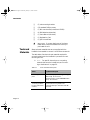
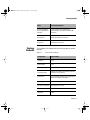
Table of Contents
About This Manual .............................................................xiii
Manual Contents ................................................................... xiii
Document Conventions .........................................................xiv
Audience ................................................................................xiv
Introduction ....................................................................... 1-1
IntraSwitch 6216M and 6224 ........................................................1-2
IntraSwitch 6216M .................................................................1-2
IntraSwitch 6224 ....................................................................1-3
IntraSwitch Components ......................................................1-4
MII Expansion Slots .........................................................1-4
Console Port ....................................................................1-4
10/100 Ports ....................................................................1-4
LEDs .................................................................................1-4
Power Supply Connector ................................................1-4
Configuration/ Management ..................................................1-5
Console/Telnet Management ..........................................1-5
Web Browser Management .............................................1-5
SNMP-Based Management ...............................................1-5
Switching Capacity ................................................................1-5
Intelligent Forwarding ...........................................................1-6
Chassis Design ........................................................................1-6
Features ..................................................................................1-7
Package Contents ...................................................................1-7
Tools and Materials ................................................................1-8
Factory Defaults .....................................................................1-9
Page iii
6216M Book Page iv Wednesday, January 27, 1999 5:26 PM
Installation ........................................................................ 2-1
Installing the IntraSwitch ..............................................................2-2
Installation Guidelines ............................................................2-2
Power Requirements .......................................................2-2
Environmental Requirements ..........................................2-2
Cooling and Airflow ........................................................2-2
Installation Overview .............................................................2-2
Rack Mounting/Desktop Placement ......................................2-3
Installing Asanté MII Modules (IntraSwitch 6216M) ..............2-5
Connecting Power .................................................................2-6
Connecting to the Network ...................................................2-6
Configuring for Management .................................................2-8
LED Indicators ................................................................... 3-1
LED Indicators ...............................................................................3-2
IntraSwitch 6216M and 6224 LED Indicators ........................3-2
IntraSwitch 6216M and 6224, Common LEDs ................3-2
IntraSwitch 6216M LEDs .................................................3-2
IntraSwitch 6224 LEDs ....................................................3-3
IntraSwitch 6216M and 6224 Port LEDs ................................3-3
IntraSwitch 6216M Function LEDs ........................................3-4
IntraSwitch 6224 Function LEDs ...........................................3-4
Setting Up For Management ........................................... 4-1
IntraSwitch Management ..............................................................4-2
Overview ................................................................................4-2
Out-of-Band Management .......................................................4-3
In-Band Management ..............................................................4-5
Page iv
6216M Book Page v Wednesday, January 27, 1999 5:26 PM
Console Management ....................................................... 5-1
Console Management ....................................................................5-2
Overview ................................................................................5-2
Management Tasks .................................................................5-3
Local Management Interface ..................................................5-4
Main Menu .......................................................................5-4
General Information Menu .....................................................5-5
Accessing the General Information Menu .......................5-5
Configuration Menu ...............................................................5-6
Logging into the Configuration Menu ..............................5-6
System Administration Configuration .............................5-9
System IP Configuration ................................................5-10
Bootstrap Configuration ................................................5-12
SNMP Configuration ......................................................5-17
Port Configuration .........................................................5-20
Spanning Tree Configuration ........................................5-27
Forwarding Database/Security Configuration ...............5-27
Image File Downloading Configuration ........................5-33
Image Downloading Through TFTP ..............................5-33
Serial Downloading Configuration ................................5-36
System Reset Options ....................................................5-39
System Log .....................................................................5-42
Set Menu Idle Time-out .................................................5-44
Changing the Password .................................................5-46
Global Port Configuration .............................................5-47
Statistics Menu .....................................................................5-50
Status Monitoring and Statistics ..................................... 6-1
Monitoring the IntraSwitch ...........................................................6-2
Viewing Current Operating Information ..............................6-2
Viewing IntraSwitch System Information ..............................6-4
Viewing Statistics ...................................................................6-5
Page v
6216M Book Page vi Wednesday, January 27, 1999 5:26 PM
Advanced Management .................................................... 7-1
Advanced Management .................................................................7-2
Spanning Tree Protocol .........................................................7-2
Configuring STP Port Parameters .........................................7-10
Web Browser Management ............................................. 8-1
Web Browser Management ...........................................................8-2
Overview ................................................................................8-2
Web Browser Management .............................................8-2
SNMP-Based Management ...............................................8-2
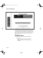
Accessing with a Web Browser ..............................................8-3
Management buttons .......................................................8-4
VLAN Management ........................................................... 9-1
VLAN Management .......................................................................9-3
Overview ................................................................................9-3
Abbreviations ..................................................................9-4
VLAN Groups ..................................................................9-4
VLAN Untagged (normal) Ports .......................................9-4
VLAN Tagged (Expansion) Ports .....................................9-5
Management VLANs ........................................................9-6
Spanning Tree Protocol in VLAN environment ...............9-6
VLAN Management Interface Options ............................9-7
VLAN Configuration ...............................................................9-7
Current Settings ...............................................................9-9
VLAN Port Attribute Configuration ......................................9-13
Current Settings .............................................................9-14
Overview: Using tagging to connect VLANs .................9-15
SNMP Management ..............................................................9-22
Page vi
6216M Book Page vii Wednesday, January 27, 1999 5:26 PM
Troubleshooting ................................................................A-1
LED Indicators ....................................................................... A-1
Technical Specifications ................................................... B-1
Network Management Platforms Supported ...................B-1
LEDs .................................................................................B-1
Connectors ......................................................................B-1
Spanning Tree Support ....................................................B-1
MAC Address Table Size ..................................................B-1
Download ........................................................................B-1
Dimensions ......................................................................B-1
Weight .............................................................................B-2
Power Specifications .......................................................B-2
Environmental Specifications ..........................................B-2
Standards Compliance .....................................................B-2
Mounting Options ...........................................................B-2
Technical Support ............................................................. C-1
Index ............................................................................. Index-1
Page vii
6216M Book Page viii Wednesday, January 27, 1999 5:26 PM
List of Figures
Figure 1-1
Figure 1-2
Figure 1-3
Figure 1-4
Figure 2-1
Figure 2-2
Figure 2-3
Figure 3-1
Figure 3-2
Figure 4-1
Figure 4-2
Figure 5-1
Figure 5-2
Figure 5-3
Figure 5-4
Figure 5-5
Figure 5-6
Figure 5-7
Figure 5-8
Figure 5-9
Figure 5-10
Figure 5-11
Figure 5-12
Figure 5-13
Figure 5-14
Figure 5-15
Figure 5-16
Figure 5-17
Figure 5-18
IntraSwitch 6216M Front Panel . . . . . . . . . . . . . . . . . . . 1-2
IntraSwitch 6216M Back Panel . . . . . . . . . . . . . . . . . . . 1-2
IntraSwitch 6224 Front Panel . . . . . . . . . . . . . . . . . . . . . 1-3
IntraSwitch 6224 Back Panel . . . . . . . . . . . . . . . . . . . . . 1-3
IntraSwitch Rack Installation . . . . . . . . . . . . . . . . . . . . . 2-3
IntraSwitch Cabling Scenarios . . . . . . . . . . . . . . . . . . . . 2-8
Local Management Interface Main Menu. . . . . . . . . . . 2-10
IntraSwitch 6216M LED Panel. . . . . . . . . . . . . . . . . . . . 3-2
IntraSwitch 6224 LED Panel . . . . . . . . . . . . . . . . . . . . . 3-3
IntraSwitch 6216M and 6224 Management Options . . . 4-3
Local Management Interface Main Menu. . . . . . . . . . . . 4-4
Local Management Interface Main Menu. . . . . . . . . . . . 5-4
General Information Menu . . . . . . . . . . . . . . . . . . . . . . . 5-5
Configuration Menu . . . . . . . . . . . . . . . . . . . . . . . . . . . . 5-6
System Administration Configuration Menu . . . . . . . . . 5-9
System IP Configuration Menu . . . . . . . . . . . . . . . . . . 5-11
BootStrap Configuration Menu. . . . . . . . . . . . . . . . . . . 5-13
SNMP Configuration Menu . . . . . . . . . . . . . . . . . . . . . 5-17
Port Configuration Menu . . . . . . . . . . . . . . . . . . . . . . . 5-21
Advanced Port Configuration Menu. . . . . . . . . . . . . . . 5-21
Forwarding DB/Security Configuration Menu . . . . . . . 5-28
Display Forwarding Database Menu . . . . . . . . . . . . . . 5-30
Image File Downloading Configuration Menu. . . . . . . 5-33
Image Downloading Menu . . . . . . . . . . . . . . . . . . . . . . 5-34
X/Y/ZModem Image File Downloading Menu . . . . . . 5-37
Setting Baud Rate . . . . . . . . . . . . . . . . . . . . . . . . . . . . . 5-38
Reset Menu . . . . . . . . . . . . . . . . . . . . . . . . . . . . . . . . . . 5-40
System Log Menu . . . . . . . . . . . . . . . . . . . . . . . . . . . . . 5-42
System Log Display . . . . . . . . . . . . . . . . . . . . . . . . . . . 5-43
Page viii
6216M Book Page ix Wednesday, January 27, 1999 5:26 PM
Figure 5-19
Figure 5-20
Figure 5-21
Figure 5-22
Figure 5-23
Figure 5-24
Figure 6-1
Figure 6-2
Figure 6-3
Figure 6-4
Figure 6-5
Figure 7-1
Figure 7-2
Figure 8-1
Figure 8-2
Figure 8-3
Figure 8-3
Figure 8-4
Figure 8-5
Figure 8-6
Figure 8-7
Figure 8-8
Figure 8-9
Figure 8-10
Figure 8-11
Figure 9-1
Figure 9-2
Figure 9-3
IntraSwitch UI Time-out Configuration Screen . . . . . . 5-44
Current Idle Time-out command line . . . . . . . . . . . . . . 5-45
Telnet Idle Time-out period . . . . . . . . . . . . . . . . . . . . . 5-45
Global Port Configuration Menu . . . . . . . . . . . . . . . . . 5-47
Global Port Configuration Help Menu . . . . . . . . . . . . . 5-48
Auto-negotiation Advertisement Summary Screen . . . 5-50
General Information Menu . . . . . . . . . . . . . . . . . . . . . . . 6-2
Port Configuration Menu . . . . . . . . . . . . . . . . . . . . . . . . 6-4
Statistics Menu . . . . . . . . . . . . . . . . . . . . . . . . . . . . . . . . 6-6
Statistics Since Last Reset . . . . . . . . . . . . . . . . . . . . . . . 6-7
Counters Screen . . . . . . . . . . . . . . . . . . . . . . . . . . . . . . . 6-8
Spanning Tree Configuration Menu . . . . . . . . . . . . . . . . 7-4
Spanning Tree Port Configuration Menu . . . . . . . . . . . 7-10
Web Browser Management Page . . . . . . . . . . . . . . . . . . 8-4
Port Selector Screen . . . . . . . . . . . . . . . . . . . . . . . . . . . . 8-6
General Information Screen . . . . . . . . . . . . . . . . . . . . . . 8-7
General Information Screen (Continued) . . . . . . . . . . . . 8-8
Statistics Screen . . . . . . . . . . . . . . . . . . . . . . . . . . . . . . . 8-9
Statistics Counters Screen. . . . . . . . . . . . . . . . . . . . . . . 8-11
Port Configuration Screen. . . . . . . . . . . . . . . . . . . . . . . 8-12
Spanning Tree Protocol Configuration . . . . . . . . . . . . . 8-13
STP Port Configuration. . . . . . . . . . . . . . . . . . . . . . . . . 8-14
SNMP Configuration Screen . . . . . . . . . . . . . . . . . . . . 8-15
Downloading Image File. . . . . . . . . . . . . . . . . . . . . . . . 8-16
Asanté Technical Support Screen . . . . . . . . . . . . . . . . . 8-18
VLAN Configuration Screen . . . . . . . . . . . . . . . . . . . . . 9-9
VLAN Port Attribute Configuration Screen . . . . . . . . . 9-13
Example of a system with tagged (expansion) ports . . 9-20
Page ix
6216M Book Page x Wednesday, January 27, 1999 5:26 PM
List of Tables
Table 1-1
Table 1-2
Table 2-1
Table 2-2
Table 2-3
Table 2-4
Table 3-1
Table 3-2
Table 3-4
Table 4-1
Table 5-1
Table 5-2
Table 5-3
Table 5-4
Table 5-5
Table 5-6
Table 5-7
Table 5-8
Table 5-9
Table 5-10
Table 5-11
Table 5-12
Table 5-13
Table 5-14
Table 6-1
Table 6-2
Table 6-3
Table 6-4
Table 6-5
Table 7-1
Tools and Materials Required . . . . . . . . . . . . . . . . . . . . 1-8
Factory Default Settings . . . . . . . . . . . . . . . . . . . . . . . . 1-9
Installation Overview . . . . . . . . . . . . . . . . . . . . . . . . . . . 2-3
10/100 Ports Cable Guidelines . . . . . . . . . . . . . . . . . . . . 2-7
100Base-FX MII Module Cable Guidelines . . . . . . . . . 2-7
10Base-FL MII Module Cable Guidelines . . . . . . . . . . 2-7
IntraSwitch 6216M and 6224Port LED Descriptions . . 3-3
IntraSwitch 6216M Indicator Light Description . . . . . . 3-4
IntraSwitch 6224 Indicator Light Descriptions . . . . . . . 3-4
Management Options . . . . . . . . . . . . . . . . . . . . . . . . . . . 4-2
Configuration Tasks . . . . . . . . . . . . . . . . . . . . . . . . . . . . 5-2
Management Tasks . . . . . . . . . . . . . . . . . . . . . . . . . . . . 5-3
Configuration Menu Options . . . . . . . . . . . . . . . . . . . . . 5-7
System Administration Configuration Menu Settings . . 5-9
System IP Configuration Menu Settings . . . . . . . . . . . 5-11
Bootstrap Configuration Menu Settings . . . . . . . . . . . 5-14
SNMP Configuration Menu Settings . . . . . . . . . . . . . . 5-18
Port Management Menu Settings . . . . . . . . . . . . . . . . . 5-22
Security Configuration Menu Settings . . . . . . . . . . . . . 5-29
Image Downloading Menu Settings . . . . . . . . . . . . . . . 5-34
X/Y/Z Downloading Menu Table . . . . . . . . . . . . . . . . 5-37
Reset Menu Settings . . . . . . . . . . . . . . . . . . . . . . . . . . 5-40
UI Time-out Settings . . . . . . . . . . . . . . . . . . . . . . . . . . 5-44
Global Port Configuration Settings . . . . . . . . . . . . . . . 5-47
General Information Menu Parameters . . . . . . . . . . . . . 6-3
IntraSwitch System Information . . . . . . . . . . . . . . . . . . 6-5
Statistics Fields on Statistics Screen . . . . . . . . . . . . . . . 6-6
Statistics Since Last Reset . . . . . . . . . . . . . . . . . . . . . . . 6-7
Counters Screen Description . . . . . . . . . . . . . . . . . . . . . 6-8
Spanning Tree Configuration Menu Settings . . . . . . . . 7-5
Page x
6216M Book Page xi Wednesday, January 27, 1999 5:26 PM
Table 7-2
Table 9-1
Table 9-2
Table 9-3
Table 9-4
Spanning Tree Port Configuration Menu Settings . . . . 7-11
System VLAN Default Settings . . . . . . . . . . . . . . . . . . . 9-7
VLAN Group Current Settings . . . . . . . . . . . . . . . . . . 9-10
Current Settings of Port Attributes . . . . . . . . . . . . . . . 9-14
Configuration used in example of tagging . . . . . . . . . . 9-21
Page xi
DRAFT
6216M Book Page xii Wednesday, January 27, 1999 5:26 PM
About This Manual
This section provides an overview of the IntraSwitch 6216M
and IntraSwitch 6224 User’s Manual. It describes chapter
contents, document conventions, and intended audience.
This chapter contains the following sections:
❏
Chapter Contents
❏
Document Conventions
❏
Audience
6216M Book Page xiii Wednesday, January 27, 1999 5:26 PM
About This Manual
About This Manual
Manual
Contents
This manual describes how to install and use the IntraSwitch
6216M and 6224 Ethernet switch.
This manual contains the following chapters and appendices:
Chapter/Appendix
1
Introduction
Describes the unit, its package contents, features,
switching capacity, management options, and
factory default settings.
2
Installation
Describes the steps required to install the unit,
connect it to the network, and configure it for
management. It also describes how to install MII
expansion modules.
LED Indicators
Describes the front panel LEDs and their use.
Setting Up For
Management
Describes management options and how to use
them to provide connections to the unit.
Console
Management
Describes how to perform basic management
functions using the Local Management Interface.
3
4
5
6
7
8
9
Describes how to view operating information and
Status
Monitoring and statistics, and how to prepare the unit for
connection to an external traffic analyzer.
Statistics
Advanced
Management
Describes how to configure the Spanning Tree
Protocol.
Web Browser
Management
Describes how to manage and monitor the
IntraSwitch using a Web Browser.
VLAN
Management
Describes the IntraSwitch’s VLAN options and
explains how to configure the unit using those
options
Appendix A,
Troubleshooting
Page xiii
Description
Provides some troubleshooting tips for isolating
problems by using the unit’s front panel LEDs.
6216M Book Page xiv Wednesday, January 27, 1999 5:26 PM
Document Conventions
Document
Conventions
Chapter/Appendix
Description
Appendix B,
Technical
Specifications
Describes the IntraSwitch technical
specifications.
Appendix C,
Technical Support
Describes how to contact Asanté Technical
Support.
The following conventions are used for instructions and
information:
❏
Audience
Commands and key words are in boldface
font.
∆
Note: Noteworthy information, which contains
suggestions or references to other sections in the
manual, is in this format.
▲
Important: Significant information that calls
attention to important features or instructions
is in this format.
This manual uses terms and concepts associated with Ethernet
networking and switches; it is recommended that the user of
this manual have a basic working knowledge of local area
networks (LANs).
Page xiv
6216M Book Page xv Wednesday, January 27, 1999 5:26 PM
About This Manual
Page xv
DRAFT
6216M Book Page 1 Wednesday, January 27, 1999 5:26 PM
1
Introduction
This chapter is an introduction to the IntraSwitch 6216M and
6224 Switches. It provides an overview of the unit and
describes its features, management and configuration
capabilities, switching capacity, and factory default settings.
This chapter contains the following sections:
❏
IntraSwitch 6216M and 6224
❏
Configuration/Management
❏
Switching Capacity
❏
Chassis Design
❏
Features
❏
Package Contents
❏
Tools and Materials Needed
❏
Factory Defaults
6216M Book Page 2 Wednesday, January 27, 1999 5:26 PM
Introduction
IntraSwitch 6216M and 6224
IntraSwitch
6216M
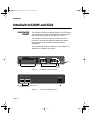
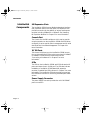
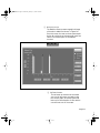
The IntraSwitch 6216M is a high-performance, 10/100 Ethernet
switch designed for building high-bandwidth workgroups and
high-speed network segments. See figures 1-1 and 1-2.
The IntraSwitch 6216M has 16 fixed 10/100 ports, which
includes two optional Asanté Media Independent Interface
(MII) expansion slots, and built-in Web-based network
management.
The two Asanté MII expansion slots allow for the addition of
100Base-FX or 10Base-FL connections.
Switched 10/100Mbps Ports
IntraSwitch 6216M
MII1
MII2
15
16
2
4
6
8
10
12
14
16
1
3
5
7
9
11
13
15
or
Power
100Mbps
FDP
Data
Uplink
Link
Normal
1
2
3
4
5
6
7
8
9
10
11
12
13
14
LEDs
Sixteen 10/100Base-T Ports
Figure 1-1
MII 2 (Port 16)
Console
Uplink
Switch
IntraSwitch 6216M Front Panel
MII 1 (Port 15)
100-240Vac Input
Two Asanté Media Independent Interface
(MII) Expansion Slots
Figure 1-2
Page 1-2
IntraSwitch 6216M Back Panel
Console
Port
6216M Book Page 3 Wednesday, January 27, 1999 5:26 PM
IntraSwitch 6224
IntraSwitch
6224
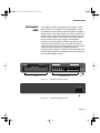
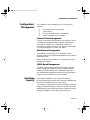
The IntraSwitch 6224 is a high performance 24-port 10/100
Ethernet switch.The IntraSwitch 6224 is designed for heavy
duty desktop users, and features a backplane that is capable of
supporting up to four Gbps of traffic.The 6224 can sustain fullduplex, full wire speed (148,800 packets per second per port)
non-blocking throughput.The IntraSwitch 6224 also supports
easy load monitoring via the front panel Led Utilization
indicators. Only the IntraSwitch 6216M model supports the
pushbutton Uplink selector, which eliminates the need for a
crossover cable, and only the 6216M supports optional internal
Asanté Fiber MII modules, which enable long distance
connections. Otherwise, the IntraSwitch 6224 and 6216M have
identical SNMP and RMON management features including the
built-in Web Management Server.
.
Switched 10/100Mbps Ports
IntraSwitch 6224
Utilization
2
4
6
8
10
12
14
16
1
3
5
7
9
11
13
15
18
20
22
24
19
21
23
Power
>1
3
5
10
25
50
75
90<
8
9
10
11
12
13
14
15
100Mbps
FDP
Data
LEDs
Link
1
2
3
4
5
6
7
16
17
18
19
20
21
22
23
24
2410/100Base-T Ports
LEDs
Figure 1-3
17
Console
Console
Port
IntraSwitch 6224 Front Panel
100-240Vac Input
Figure 1-4
IntraSwitch 6224 Back Panel
Page 1-3
6216M Book Page 4 Wednesday, January 27, 1999 5:26 PM
Introduction
IntraSwitch
Components
MII Expansion Slots
The IntraSwitch 6216M has two Media Independent Interface
(MII) expansion slots on the back panel.The expansion slots
provide connections for the addition of various media access
modules, including: 100Base-FX or 10Base-FL. See “Installing
MII Expansion Modules” in Chapter 2 for more information.
Console Port
The Console Port is a DB-9 serial port which may be used for
console operations on the IntraSwitch 6216M and 6224. When
configured, it can be used for Switch management and for serial
download. See “Out-of-Band Management” in Chapter 4 for
more information.
10/100 Ports
The sixteen 10/100 ports on the IntraSwitch 6216M (twentyfour on the IntraSwitch 6224) provide connections for 10Base-T
or 100Base-TX (Fast Ethernet) network devices. See
“Connecting to the Network” in Chapter 2 for more
information.
LEDs
The LEDs on the IntraSwitch 6216M and 6224 indicate the AC
power and status of each 10/100 port.The LEDs also indicate
installation of IntraSwitch 6216M Asanté MII expansion
modules, if installed. See “LED Indicators” in Chapter 3 for more
information.The IntraSwitch 6224 also provides a convenient
LED Utilization indicator for monitoring total backplane traffic
volume.
Power Supply Connector
The power supply connector provides the unit’s 100-240VAC
power connection.
Page 1-4
6216M Book Page 5 Wednesday, January 27, 1999 5:26 PM
Configuration/ Management
Configuration/
Management
The IntraSwitch can be managed by any of the following
methods:
❏
❏
❏
❏
Out-of-band (via the console port)
In-band Telnet
HTTP server (Web browser management)
SNMP-compatible network manager
Console/Telnet Management
Through Console and Telnet operation, the IntraSwitch can be
configured and managed manually using the Configuration
Menu option. In addition to “Configuration,” options are
provided for “General Information” and “Statistics.” See Chapter
5 “Console Management” for more information.
Web Browser Management
The IntraSwitch has a built-in HTTP (Hypertext Transfer
Protocol) server which facilitates management with any World
Wide Web browser.
Refer to Chapter 8 for information on using a Web browser to
manage the IntraSwitch.
SNMP-Based Management
The SNMP (Simple Network Management Protocol) may be
used to manage the IntraSwitch and any installed expansion
module. Any SNMP-based network management application
such as Web-based management software can be used. Refer to
Chapter 4 and to Chapter 8 for more information.
Switching
Capacity
Each 10Base-T/100Base-TX port can forward Ethernet
minimum-sized 64-byte packets at the maximum attainable rate
of 14,880 or 148,000 packets per second (pps).
The IntraSwitch fully supports the 802.1d transparent Ethernet
bridging standard. IEEE 802.1d compliance provides automatic
address learning, packet filtering, protection against corrupted
frames and fragments, and the Spanning Tree Protocol.
Page 1-5
6216M Book Page 6 Wednesday, January 27, 1999 5:26 PM
Introduction
Intelligent
Forwarding
The Asanté switching engine supports automatic fragment free
packet forwarding. Fragment free switch mode allows the
switch to make the fastest possible switching decisions without
forwarding runt packages on the network.The switch
automatically drops (or filters) illegally short packets known as
runts, which prevent bad packets from propagating across
segments. Runts are usually the result of packet collisions on a
congested network.
The Asanté switching engine also supports store and forward
switching. It will automatically choose the safest and fastest
method of switching if the source and destination are at the
same speed. If the speeds are different, such as for a 10Mbps
workstation connected to a 100Mbps server, the switch will
buffer and read the entire packet, perform a data validity check,
then forward the packet at the new speed. With Asanté
Intelligent Forwarding your FriendlyNet Switch will
automatically pick the best and fastest switching method for
you.
∆
Chassis Design
The IntraSwitch chassis is rack-mountable and is 1.5 RU (rack
units) high.
▲
Page 1-6
Note: Intelligent Forwarding is an automatic feature of the IntraSwitch and cannot be altered by
the user.
Important! Do not remove the IntraSwitch’s
cover.This will invalidate the Asanté Limited
Lifetime Warranty. Refer service to qualified service personnel.
6216M Book Page 7 Wednesday, January 27, 1999 5:26 PM
Features
Features
The IntraSwitch has the following features:
❏
16 (IntraSwitch 6216M) or 24 (IntraSwitch 6224)
fixed, 10/100 switched ports with RJ-45 connectors.
❏
Two optional Asanté MII expansion slots (IntraSwitch
6216M only), which replace ports 15 and 16.The
slots accommodate 100Base-FX, and 10Base-FL modules.
∆
Package
Contents
Note: Using the Asanté MII Module will disable
the respective front panel 10/100 ports 15 or 16.
❏
HTTP server which provides Java-enabled front panel
view and SNMP management and configuration via
any supported World Wide Web browser
❏
Telnet (in-band) and Console (out-of-band) management
❏
Support for 8,192 MAC addresses per unit
❏
Full duplex support on all ports
❏
NWay auto-negotiation on 10/100 ports
❏
Full 100Mbps wire-speed, non-blocking packet transfers for total throughput of 1Gbps per unit
(IntraSwitch 6216M) or 4Gbps per unit (IntraSwitch
6224)
❏
BootP and TFTP support
❏
RMON support (1 group)
❏
MIB II, Bridge MIB support
❏
Private MIB support (provides IP-to-port mapping)
❏
802.1d Spanning Tree support
The IntraSwitch is shipped with the following items:
❏
(1) IntraSwitch Ethernet switch
❏
(1) power cord
Page 1-7
6216M Book Page 8 Wednesday, January 27, 1999 5:26 PM
Introduction
Tools and
Materials
❏
(2) rack-mounting brackets
❏
(16) standard Phillips screws
❏
❏
(1) MII cover bracket (IntraSwitch 6216M)
(4) Self-adhesive rubber feet)
❏
(1) User’s Manual (this book)
❏
❏
(1) Registration Card
(1) Quick Install Card
▲
Important! If you are missing any of the items
listed above, contact the dealer from whom you
purchased the unit.
Some tools and materials that are not supplied with the
IntraSwitch are needed to connect it to an Ethernet network.
The table below lists the tools and materials required for
connecting devices to the IntraSwitch’s ports and for rackmounting the unit.
∆
Table 1-1
Note: For specific instructions on connecting
network devices to the IntraSwitch, see “Connecting to the Network” on page 2-6.
Tools and Materials Required
Action
Tool/Material Required
Connecting 10/100
ports
Standard Category 5 UTP straight-through
cable with RJ-45 connectors.
Standard Category 5 UTP cross-over cables
with RJ-45 connectors.
Connecting 100BaseFX port (optional MII
module)
Page 1-8
Dual 62.5/125 micron graded-index
multimode fiber-optic cable fitted with SC
connectors.
6216M Book Page 9 Wednesday, January 27, 1999 5:26 PM
Factory Defaults
Factory
Defaults
Action
Tool/Material Required
Connecting 10BaseFL port (optional MII
modules)
Dual 62.5/125 micron graded-index
multimode fiber optic cable fitted with ST
connectors.
Connecting to the
Console port
Straight-through RS-232 cable with a 9-pin
male D-subminiature connector.
Rack-mounting the
IntraSwitch
Phillips screwdriver for mounting the two
rack brackets on the unit.
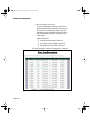
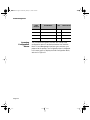
The IntraSwitch is shipped with the following factory default
settings:
Table 1-2
Factory Default Settings
Configuration
Default Setting
IP address
0.0.0.0
Subnet Mask
0.0.0.0
Default Gateway
0.0.0.0
Switching Mode
Intelligent Forwarding (Automatic Fragment
Free/Store and Forward)
10/100 Ports
Auto-negotiation enabled; auto-negotiates to
10Mbps or 100Mbps, half duplex
Spanning Tree
Enabled
BC Storm Threshold
7000 packets per second
Console Baud Rate
9600 Baud
Password
Asante
Page 1-9
6216M Book Page 10 Wednesday, January 27, 1999 5:26 PM
Factory Defaults
Page 1-10
DRAFT
6216M Book Page 1 Wednesday, January 27, 1999 5:26 PM
2
Installation
This chapter explains how to install, connect, and configure
the IntraSwitch 6216M and 6224 to work with your network. It
also explains how to install an MII expansion module in the
IntraSwitch 6216M.
This chapter contains the following sections:
❏
Installation Guidelines
❏
Installation Overview
❏
Rack Mounting/Desktop Placement
❏
Installing Asanté MII Modules (IntraSwitch
6216M Only)
❏
Connecting Power
❏
IntraSwitch Power Sequence
❏
Connecting to the Network
❏
Configuring for Management
6216M Book Page 2 Wednesday, January 27, 1999 5:26 PM
Installation
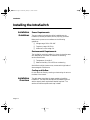
Installing the IntraSwitch
Installation
Guidelines
Power Requirements
The source electrical outlet should be installed near the
IntraSwitch, be easily accessible, and be properly grounded.
Make sure the power source adheres to the following
guidelines:
❏
❏
❏
Voltage range: 100 to 240 VAC
Frequency range: 60/50 Hz
Maximum current range: 2 A
Environmental Requirements
The IntraSwitch must be installed in a clean, dry, dust-free area
with adequate air circulation to maintain the following
environmental limits:
❏
❏
Temperature: 0° to 40° C
Relative Humidity: 5% to 85% non-condensing
Avoid direct sunlight, heat sources, or areas with high levels of
electromagnetic interference.
Cooling and Airflow
Do not restrict air flow by covering or obstructing air vents on
the sides of the chassis.
Installation
Overview
Page 2-2
The table below describes the steps needed to install the
IntraSwitch. The steps that are optional are labeled “optional”
and the steps that are required are labeled “required.” The
sections that follow explain each step in detail.
6216M Book Page 3 Wednesday, January 27, 1999 5:26 PM
Rack Mounting/Desktop Placement
Table 2-1
Installation Overview
Step
Action
1 (required)
Open the box and check the contents.
See “Package Contents” on page 1-7 for a complete
list of the items included with your IntraSwitch.
2 (optional)
Install MII expansion module(s), if any.
See “Installing MII Modules” on page 2-5.
3 (required)
Install the IntraSwitch in an equipment rack or prepare
it for desktop placement.
See “Rack Mounting/Desktop Placement” on page 2-3.
4 (required)
Connect the power supply.
See “Connecting Power” on page 2-6.
5 (required)
Connect network devices to the IntraSwitch.
See “Connecting to the Network” on page 2-6.
6 (optional)
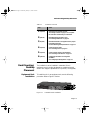
Rack Mounting/
Desktop
Placement
Equipment Rack
Installation
Configure the IntraSwitch for management
capabilities.
See “Configuring for Management” on page 2-8.
The IntraSwitch can be installed in a standard 19-inch
equipment rack. It can also be placed on a stable horizontal
surface with support capabilities of 12 pounds (5.4 kilograms).
To install the unit in an equipment rack, use the following
procedure. Refer to Figure 2-1 below.
Power
IntraSwitch 6224
Utilization
>1
100Mbps
3
5
10
25
50
75
90<
10
11
12
13
14
15
Switched 10/100Mbp
2
4
FDP
s Ports
6
8
10
12
14
7
9
11
13
Data
16
18
20
22
24
15
17
19
21
23
Link
1
2
3
4
5
6
7
8
9
16
17
18
19
20
21
22
23
24
1
Figure 2-1
3
5
Console
IntraSwitch Rack Installation
Page 2-3
6216M Book Page 4 Wednesday, January 27, 1999 5:26 PM
Installation
▲
Important! Disconnect all cables from the
IntraSwitch before continuing.
∆
Note: You can install the IntraSwitch in an
equipment rack before installing an expansion
module.
1
2
Place the IntraSwitch on a flat, stable surface.
3
Insert six screws (supplied) into the holes and
tighten with a Phillips screwdriver.
4
Repeat the two previous steps for the unit’s
other side.
5
6
Place the unit in the equipment rack.
▲
Important! Make sure the unit is supported
until all the mounting screws for each bracket
are secured to the equipment rack. Failure to do
so could cause the unit to fall, resulting in personal injury or damage to the unit, or both.
Locate a rack-mounting bracket (supplied) and
place it over the mounting holes on one side of
the unit.
Secure the unit by screwing its mounting brackets to the equipment rack.
If you are installing an MII module at this time,
proceed to “Installing MII Modules” on page 2-5.
If you are not installing an MII module at this
time, proceed to “Connecting Power” on
page 2-6.
Free-Standing/
Desktop
Installation
Page 2-4
The IntraSwitch has four rubber feet on the bottom of the
chassis that allow for free-standing installation of the unit.
For free-standing/desktop placement:
6216M Book Page 5 Wednesday, January 27, 1999 5:26 PM
Installing Asanté MII Modules (IntraSwitch 6216M Only)
Installing
Asanté MII
Modules
(IntraSwitch
6216M Only)
1
Attach the four rubber pads (supplied) to the
bottom of each corner of the IntraSwitch.
2
Place the unit on a flat surface with a minimum
area of 17.1” x 13.5” (434.3 mm x 342.9 mm)
and support capacity of 12 lbs (5 kg).
Make sure there is enough ventilation space
between the IntraSwitch and surrounding
objects.
The IntraSwitch 6216M has two optional Media Independent
Interface (MII) expansion slots on the rear panel which provide
for connection to various types of media access modules,
including:
❏
❏
Asanté 100Base-FX
Asanté 10Base-FL
The MII expansion modules comply with IEEE 802.3 and
802.3u specifications and are sold separately.To install an MII
expansion module:
▲
Important! The MII expansion modules are
hot-swappable; you can install or remove a module without turning off power.
1
Align the bottom of the MII module with the rails
on the inside of the MII 1 or MII 2 slot. Slide the
module into the expansion slot until it stops, then
push the module in gently until it seats with the
connector.
2
Observe the MII 1 and MII 2 LED indicators on
the front panel.The LEDs will indicate proper
insertion of the modules.
∆
Note: When MII 1 and/or MII 2 modules are
installed, port 15 (MII 1) or port 16 (MII 2) will
be disabled.
Page 2-5
6216M Book Page 6 Wednesday, January 27, 1999 5:26 PM
Installation
Connecting
Power
To connect power to the IntraSwitch:
▲
Important! Carefully review the power
requirements on page 2-2 before connecting
power to the IntraSwitch.
1
Plug one end of the supplied power cord into
the power connector on the back of the unit.
2
3
Plug the other end into a grounded AC outlet.
The front panel LEDs blink and the Power LED
illuminates.
▲
Important! If the power does not come
on, refer to Appendix A,“Troubleshooting.”
The unit is ready for connection to the network.
Connecting to
the Network
10/100 Ports
Cabling Procedures
The IntraSwitch unit may be connected to an Ethernet
network, with the unit powered either on or off.
1
Connect network devices to the IntraSwitch, following the cable guidelines outlined below.
2
After the unit is connected to the network, it
can be configured for management capabilities.
See “Configuring for Management” on page 2-8.
The 16 fixed 10/100 ports allow for the connection of 10Base-T
or 100Base-TX network devices. The ports are compatible with
IEEE 802.3 and 802.3u standards.
▲
Page 2-6
Important! The IntraSwitch must be located
within 100 meters of its attached 10Base-T or
100Base-TX devices.
6216M Book Page 7 Wednesday, January 27, 1999 5:26 PM
Connecting to the Network
Table 2-2
MII Expansion Ports
Cabling Procedures
100Base-FX
Module
10Base-FL
Module
Cabling Scenarios
10/100 Ports Cable Guidelines
Connecting To
Cable Required
Network Station
Category 5 UTP (Unshielded Twisted-Pair) straightthrough cable (100 meters maximum) with RJ-45
connectors.
Repeater/Hub
Category 5, UTP cross-over cable (100 meters
maximum) with RJ-45 connectors.
Repeater/Hub’s
Uplink port
Category 5, UTP straight-through cable (100 meters
maximum) with RJ-45 connectors.
The optional Asanté MII expansion slots on the rear panel allow
for the connection of Asanté fibre optic 100Base-FX, or 10BaseFL media modules.
Table 2-3
100Base-FX MII Module Cable Guidelines
Connecting To
Cable Required
All Network
Devices
Dual 62.5/125 micron graded-index multimode fiberoptic cable with an SC connector.
Table 2-4
10Base-FL MII Module Cable Guidelines
Connecting To
Cable Required
ST Connector
All Network
Devices
Dual 62.5/125 micron graded-index multimode fiberoptic cable with a dual ST connector.
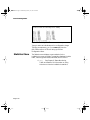
The following diagram illustrates some cabling scenarios
available with the IntraSwitch units. Note that the rear panel
MII connections do not apply to the IntraSwitch 6224
Page 2-7
6216M Book Page 8 Wednesday, January 27, 1999 5:26 PM
Installation
3
2
1
4
1 2 3 4
5 6 7 8
6
5
Partition
Col
Pwr
7
10
9
8
11
12
9 10 11 12
100BASE-TX Ports
Link/Receive
AsantéFAST 100 Hub
Repeater/Hub — UPLINK Port
MII connection
must be fibre
(2km max length)
from MII port
on rear panel
from port 16 (Uplink)
Switched 10/100Mbps Ports
MII 1
MII 2
15
16
Power
2
4
6
8
10
12
14
16
1
3
5
7
9
11
13
15
or
100Mbps
FDP
Console
Data
Port 16 in Uplink mode can
be connected to hub using
straight-through cable
(100m max. length)
Uplink
Link
Normal
1
2
3
4
5
6
7
8
9
10
11
12
13
14
Uplink
straight-through cable
(100m max. length)
straight-through cable
(100m max. length)
cross-over cable
(100m max. length)
1
2
1 2 3 4
5 6 7 8
1
Partition
Col
1 2 3 4
Col
1 2 3 4
Pwr
5 6 7 8
9 10 11 12
Link/Receive
2
3
4
5
6
7
8
9
10
11
5
6
7
9
8
100BASE-TX Ports
10
11
12
AsantéFAST 100 Hub
Repeater/Hub — STANDARD Port
Pwr
1
4
9 10 11 12
Link/Receive
straight-through cable
(100m max. length)
Partition
3
Partition
Col
Pwr
12
5 6 7 8
2
3
4
5
6
7
8
9
10
11
12
9 10 11 12
Link/Receive
100BASE-TX Ports
AsantéFAST 100 Hub
Repeater/Hub — UPLINK Port
AsantéFAST 100 Hub
100BASE-TX Ports
Repeater/Hub — Standard Port
100Base-TX
Server
straight-through cable
(100m max. length)
Printer
Figure 2-2
∆
Configuring for
Management
Page 2-8
IntraSwitch Cabling Scenarios
Note: Pressing the Uplink switch toggles the
usage of port 16 from normal to uplink or vice
versa.This uplink feature is available only for
regular RJ-45 port, and not for MII ports. When
port 16 is used for uplink, the connection
between port 16 to standard hub is straightthrough cable.
To use the IntraSwitch as a managed switch, it must be
configured with an IP address.This can be accomplished in one
of two ways:
❏
❏
BootP Configuration
Network
Station
automatically using BootP (default)
manually via the unit’s Console port
The IntraSwitch is shipped with BootP support. BootP allows
the IntraSwitch to be automatically configured with an IP
6216M Book Page 9 Wednesday, January 27, 1999 5:26 PM
Configuring for Management
address when it is connected to the network and is powered
on, if your network contains a BootP server configured with
available, valid IP addresses.
▲
Important! BootP configuration only works if
the IntraSwitch does not have an IP address
assigned to it.
1
Make sure your network has a BootP server configured with a valid IP address entry for the
IntraSwitch.
2
When the IntraSwitch is connected to the network and is powered on, it automatically transmits a BootP request across the network (up to
10times) until it receives a valid IP address from
the BootP server.
3
After an IP address is received, the IntraSwitch
can be managed via in-band access. See Chapter
4 for more information.
To verify that a valid IP address was received, use a tool such as
Ping1 to try and access the IntraSwitch; if you can access the
IntraSwitch, it is properly configured with an IP address.
See “Bootstrap Configuration” in Chapter 5 for more
information on using BootP.
Console
Configuration
To manually configure the IntraSwitch with an IP address via its
Console port, use a VT100 terminal or emulator (such as Hyper
Terminal, ProComm, or ZTerm) running on a workstation or
personal computer to connect to the switch’s Local Management Interface.
1. Ping is an application that can be used to test whether a remote device is
properly connected to a network.
Page 2-9
6216M Book Page 10 Wednesday, January 27, 1999 5:26 PM
Installation
1
Using a straight-through
RS-232 cable with a 9pin male D-subminiature plug at one end, connect a terminal or workstation (PC or Macintosh)
running a terminal emulator to the Consoleport
on the front of the IntraSwitch.
2
Make sure both units are powered on.
If using a PC with a terminal emulator, make
sure it is configured with the following terminal
settings:
❏ Baud: 9600
❏ Data Bits: 8
❏ Parity: None
❏ Stop Bits: 1
❏ Flow Control: None
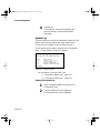
3
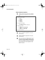
Once connected, the Local Management Main
Menu appears on the terminal screen, as shown
in Figure 2-3.
Figure 2-3
Page 2-10
Local Management Interface Main Menu
4
Type c to open the Configuration Menu.
The “Enter Password” prompt appears.
5
Type your password at the prompt.
▲
Important! The default password is
Asante
. The password is case-sensitive.
6216M Book Page 11 Wednesday, January 27, 1999 5:26 PM
Configuring for Management
For information on changing the password,
see “Changing the Password” in Chapter 5.
6
7
8
Type i to open the Switch IP Configuration menu.
Type i to select the option “Set IP Address.”
Type the IP address to be assigned to the
IntraSwitch at the prompt.
∆
9
10
Note: Depending on your network configuration, you may also need to set subnet mask
and default gateway (router) information.
See “System IP Configuration” in Chapter 5
for instructions.
Press Return
.
Type q to return to the Configuration Menu.
The IntraSwitch is configured with an IP address and can now
be managed via in-band access. See Chapter 4,“Setting Up For
Management” for more information.
Page 2-11
6216M Book Page 12 Wednesday, January 27, 1999 5:26 PM
Installation
Page 2-12
DRAFT
6216M Book Page 1 Wednesday, January 27, 1999 5:26 PM
3
LED Indicators
This chapter describes the IntraSwitch 6216M and 6224’s front
panel and explains how to interpret its port LEDs and other
function indicators.
This chapter contains the following sections:
❏
LED Indicators
❏
Port LEDs
❏
Function Indicator Lights
6216M Book Page 2 Wednesday, January 27, 1999 5:26 PM
LED Indicators
LED Indicators
IntraSwitch
6216M and 6224
LED Indicators
IntraSwitch 6216M and 6224, Common LEDs
The IntraSwitch 6216M and 6224 front panels contain LEDs
which provide a visual indication for each 10/100TX port.The
LEDs may also be used to assist with troubleshooting. See
Figures 3-1 and 3-2.The four rows of port LEDs display:
❏
❏
❏
❏
100Mbps (100Mbps operation)
FDP (full duplex operation)
Data
Link
Both IntraSwitch 6216M and 6224 contain an LED which
indicates AC power on when lit.
IntraSwitch 6216M LEDs
In addition to the LEDs in common with the IntraSwitch 6224
as described above, the IntraSwitch 6216M has MII 1 and MII 2
LEDs.These LEDs convey the presence of the MII expansion
modules (if installed).
IntraSwitch 6216M
MII1
MII2
15
16
Power
100Mbps
FDP
Data
Link
1
2
3
4
5
6
Figure 3-1
Page 3-2
7
8
9
10
11
12
13
IntraSwitch 6216M LED Panel
14
6216M Book Page 3 Wednesday, January 27, 1999 5:26 PM
IntraSwitch 6216M and 6224 Port LEDs
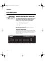
IntraSwitch 6224 LEDs
In addition to the LEDs in common with the IntraSwitch 6216M
as described above, the IntraSwitch 6224 has a row of eight
LEDs which display the percentage of Switch utilization.
IntraSwitch 6224
Utilization
Power
>1
3
5
10
25
50
75
90<
8
9
10
11
12
13
14
15
100Mbps
FDP
Data
Link
1
2
3
4
5
6
7
Figure 3-2
IntraSwitch
6216M and 6224
Port LEDs
16
17
18
19
20
21
22
23
24
IntraSwitch 6224 LED Panel
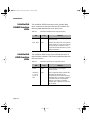
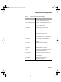
The IntraSwitch 6216M and 6224 have four rows of LEDs.The
following table describes their color and function.
Table 3-1
IntraSwitch 6216M and 6224Port LED Descriptions
LED
Color
Meaning
100Mbps
green
The port speed is 100Mbps.
FDP
amber
The port is in full duplex mode.
Note: Full duplex means that a port
can transmit and receive at the same
time.
Data
green
Traffic activity is occurring on the port,
transmit [TX] or receive [RX].
Link
green
The port is connected to a poweredon node or other network device.
∆
Note: For information on using the LEDs to
troubleshoot problems with your network, see
Appendix A,“Troubleshooting.”
Page 3-3
6216M Book Page 4 Wednesday, January 27, 1999 5:26 PM
LED Indicators
IntraSwitch
6216M Function
LEDs
The IntraSwitch 6216M has three function indicator lights,
which comprise one Power and two MII LED indicators.The
following table describes their color and function.
Table 3-2
LED
IntraSwitch
6224 Function
LEDs
Color
Meaning
Power
green
The IntraSwitch is receiving AC
electrical power.
MII 1, MII 2
green
Indicates the presence of an Asanté MII
Module in MII slot 1 (port 15) or MII slot
two (port 16). No connection or link is
required for the MII LED to be lit, just the
module installation.
The IntraSwitch 6224 has one Power indicator and a row of
eight Utilization indicators.The following table describes their
color and function.
Table 3-3
LED
Page 3-4
IntraSwitch 6216M Indicator Light Description
IntraSwitch 6224 Indicator Light Descriptions
Color
Meaning
Power
green
The IntraSwitch is receiving AC
electrical power.
Utilization
1, 3, 5, 10,
25, 50, 75,
90%
green
Row of eight LEDs which Indicates the
percentage of utilization of the
IntraSwitch ports. The LEDs will light if
backplane traffic is less than or equal to
the indicated value. Total backplane
capacity is four Gbps. If utilization
indicates 25% or greater, the LED color
will be amber.
DRAFT
6216M Book Page 1 Wednesday, January 27, 1999 5:26 PM
4
Setting Up For
Management
This chapter describes the IntraSwitch 6216M and 6224’s
management options and explains how to connect to the unit
using those options.
This chapter contains the following sections:
❏
Overview
❏
Management Scenarios
❏
Out-of-Band Management
❏
In-Band Management
6216M Book Page 2 Wednesday, January 27, 1999 5:26 PM
Setting Up For Management
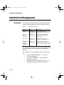
IntraSwitch Management
Overview
The IntraSwitch 6216M and 6224 and any installed Asanté MII
Modules can be managed using any of the following methods:
Table 4-1
Management Options
Method
Type
Description
Console
out-of-band
management
local connection to the
IntraSwitch via the Console port
Telnet
(four sessions
maximum)
in-band
management
remote connection over the
network to the IntraSwitch via
Telnet session
HTTP Server
in-band
management
remote connection to the
IntraSwitch via a Web browser
SNMP-Based
Network
Management
Software
in-band
management
remote connection to the
IntraSwitch via any SNMP-based
network management application
This chapter describes how to connect to the IntraSwitch using
either out-of-band or in-band management, as illustrated in
Figure 4-1.
For information on each management method, see the following:
❏
❏
❏
Page 4-2
Console or Telnet management — see Chapter
5, Console Management.
HTTP Server management — see Web Browser
Management, Chapter 8
SNMP-based network management software — see
SNMP-Based Management Software on page 4-6.
6216M Book Page 3 Wednesday, January 27, 1999 5:26 PM
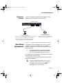
Out-of-Band Management
Management
Scenarios
The following diagram illustrates the management options
available with the IntraSwitch 6216M and 6224.
IntraSwitch 6216M
Switched 10/100Mbps Ports
MII1
MII2
15
16
Power
2
4
6
8
10
12
5
7
9
11
14
16
or
100Mbps
Console
FDP
Data
Uplink
Link
Normal
1
2
3
4
5
6
7
8
9
10
11
12
13
14
Uplink
1
3
13
15
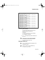
IntraStack 6014DSB
Stand-alone Terminal or PC
Workstation
Out-of-Band Management:
In-Band Management:
• Telnet connection to the IntraSwitch's Local Management Interface
• Direct connection to the IntraSwitch's Local
Management Interface via the Console port
• Connect to the IntraSwitch's HTTP server via a Web browser
• Connect to the IntraSwitch via any SNMP-based network
management software application such as IntraSpection
Figure 4-1
Out-of-Band
Management
IntraSwitch 6216M and 6224 Management Options
Out-of-band network management allows you to configure,
manage, and monitor the IntraSwitch and any installed
expansion modules.You can perform these functions via the
following method:
❏
By attaching a terminal (or a terminal emulator)
to the IntraSwitch’s Console port and using the
menu-driven Local Management Interface
.
Out-of-band network management is guaranteed even when the
in-band Ethernet network is down.
To access the IntraSwitch Local Management Interface using
out-of-band management:
1
Connect a stand-alone terminal or a PC running
a terminal emulator directly to the IntraSwitch’s
Console port using a straight-through
RS-232
serial cable with a male connector.
Page 4-3
6216M Book Page 4 Wednesday, January 27, 1999 5:26 PM
Setting Up For Management
2
Make sure both units are powered on.
If using a PC or Mac with a terminal emulator to
connect to the Console port, make sure it is configured with the following terminal settings:
❏ Baud rate: 9600
❏ Data Bits: 8
❏ Parity: None
❏ Stop Bits: 1
❏ Flow Control: None
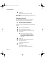
3
Figure 4-2
Once connected, the Local Management Interface Main Menu appears on the screen, as
shown in Figure 4-2.
Local Management Interface Main Menu
See Chapter 5,“Console Management,” for information on using the Local Management Interface to manage the IntraSwitch and any installed
expansion modules.
▲
Page 4-4
Important! A password is needed to access
the Configuration Menu. The default password
is Asante
. The password is case-sensitive.
6216M Book Page 5 Wednesday, January 27, 1999 5:26 PM
In-Band Management
In-Band
Management
In-band network management allows you to manage, control,
and monitor the IntraSwitch and any installed expansion
modules over the Ethernet network.
You can perform these functions by accessing the IntraSwitch
via any of the following methods:
❏
By connecting with a Telnet program and using
the Local Management Interface
.
❏
By connecting with any common World Wide
Web browser, and using the Web Management
Interface.
❏
By connecting with any SNMP-based network
management application and using its interface.
To manage the IntraSwitch via in-band management:
1
Make sure the network to which the IntraSwitch
is connected is functioning.
2
Make sure the IntraSwitch is configured with
valid IP information.
See “Configuring for Management” on page 2-8.
3
Connect to the IntraSwitch via Telnet, with a
Web browser, or with any SNMP-based network
management application.
Telnet
See Chapter 5, Console Management, for information on managing the IntraSwitch.
∆
Note: Almost all management screens using
a Telnet are identical to those of the out-ofband Console interface.
Web Browser
Refer to Chapter 8, Web Browser Management
Manual, for information on managing the
IntraSwitch with a Web browser.
Page 4-5
6216M Book Page 6 Wednesday, January 27, 1999 5:26 PM
Setting Up For Management
SNMP-Based Management Software
Refer to your SNMP Software Manual for information on managing the IntraSwitch with SNMPbased management software.
The Asanté private MIB for the IntraSwitch is
available from the Asanté ftp site, ftp.asante.com.
Page 4-6
DRAFT
6216M Book Page 1 Wednesday, January 27, 1999 5:26 PM
5
Console
Management
This chapter describes how to manage the IntraSwitch 6216M
and 6224 using the out-of-band Console or in-band Telnet
interface.
This chapter contains the following sections:
❏
Overview
❏
Configuration Tasks
❏
Management Tasks
❏
Local Management Interface
❏
General Information Menu
❏
Configuration Menu
❏
❏
Logging into the Configuration
Menu
Statistics Menu
6216M Book Page 2 Wednesday, January 27, 1999 5:26 PM
Console Management
Console Management
Overview
The IntraSwitch 6216M and 6224’s Local Management Interface
is a menu-driven application which provides management and
configuration support for the unit and each of its ports.
The Local Management Interface can be accessed via two
methods:
❏
❏
Out-of-band connection to the Console port.
In-band connection via Telnet (foursessions
maximum).
This section describes each menu within the Local
Management Interface as well as how to perform the
configuration/management tasks outlined in Tables 5-1 and 5-2.
Table 5-1
Page 5-2
Configuration Tasks
Configuration Task
Page
Logging into the Configuration Menu
page 5-6
System Administration Information
page 5-10
Changing System IP Information
page 5-12
Changing the Boot Bank Number
page 5-15
Executing Software Locally
page 5-15
Loading Software Remotely
page 5-16
Changing Community Strings
page 5-18
Configuring Duplex Mode
page 5-24
Configuring Auto-Negotiation
page 5-25
6216M Book Page 3 Wednesday, January 27, 1999 5:26 PM
Management Tasks
Management
Tasks
Table 5-2
Management Tasks
Management Task
Page
Enabling Traps
page 5-19
Adding a Trap Receiver
page 5-19
Deleting a Trap Receiver
page 5-20
Enabling or Disabling a Port
page 5-23
Performing a Software Upgrade at Runtime
page 5-35
Displaying the MAC Address Table
page 5-29
Searching the MAC Address Table
page 5-30
Setting the MAC Address Age-Out Time
page 5-31
Enabling the Duplicated-IP Trap
page 5-32
Viewing the Trap Log
page 5-32
Resetting the IntraSwitch
page 5-41
Scheduling a Reset
page 5-41
Viewing the System Log
page 5-42
Clearing the System Log
page 5-43
Setting the Console and Telnet Idle Time-out Period
page 5-44
Changing the Password
page 5-46
∆
Note: For information on monitoring statistics,
viewing the IntraSwitch’s current operating and
system information, see Chapter 6,“Status Monitoring,Traffic, and Statistics.”
Page 5-3
6216M Book Page 4 Wednesday, January 27, 1999 5:26 PM
Console Management
Local
Management
Interface
After you connect to the Local Management Interface using
either out-of-band Console or in-band Telnet connection as
described in Chapter 4, the Main Menu appears as shown in
Figure 5-1.
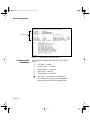
Main Menu
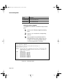
Figure 5-1
Local Management Interface Main Menu
From the Main Menu, you can access three submenus:
❏
❏
❏
General Information — page 5-5
Configuration — page 5-6
Statistics — page 5-50
If you are using Telnet, a fourth option will be available — Close
Connection. This option closes your remote connection to the
IntraSwitch’s Local Management Interface.
Accessing a
Submenu
Exiting a
Submenu
Page 5-4
To access a submenu, type the command letter of the
corresponding option (e.g., type g for General Information).
To exit a submenu, type q. To exit a command line (e.g., the
“Set Password” option in the Configuration Menu), press ctrl-c.
6216M Book Page 5 Wednesday, January 27, 1999 5:26 PM
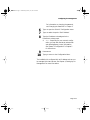
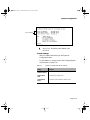
General Information Menu
General
Information
Menu
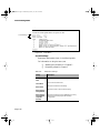
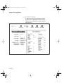
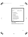
The General Information Menu displays the IntraSwitch’s
current operating information; such as its name, IP address, and
boot information.
∆
Note: The information displayed on this screen is
read-only.
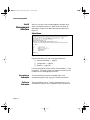
Accessing the General Information Menu
❏
Type g from the Local Management Interface Main
Menu. A screen similar to Figure 5-2 appears:
Figure 5-2
▲
General Information Menu
Important! For a description of each parameter on the General Information Menu, see “General Information Menu Parameters” on page 6-3.
To exit the General Information Menu, press any key on your
keyboard.
Page 5-5
6216M Book Page 6 Wednesday, January 27, 1999 5:26 PM
Console Management
Configuration
Menu
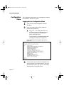
The Configuration Menu allows you to manage and configure
the IntraSwitch and each of its ports.
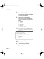
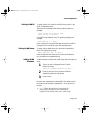
Logging into the Configuration Menu
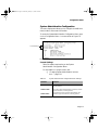
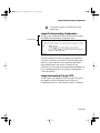
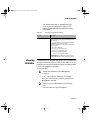
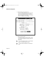
1
Type c from the Local Management Interface
Main Menu.
2
Enter your password at the “Enter Password”
prompt, then press Return
.
▲
Important: The default password when
you first access the Configuration Menu is
Asante
. The password is case-sensitive;
enter it exactly as shown.
For information on changing passwords, see
“Changing the Password” on page 5-46.
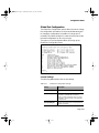
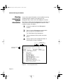
The Configuration Menu appears, as shown in
Figure 5-3.
Figure 5-3
3
Page 5-6
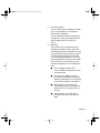
Configuration Menu
From this menu you can access configuration submenus by typing the command letter of the corresponding menu option (e.g., type a for the System
Administration Configuration Menu).
6216M Book Page 7 Wednesday, January 27, 1999 5:26 PM
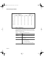
Logging into the Configuration Menu
Configuration Menu Options
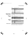
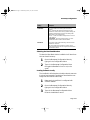
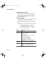
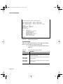
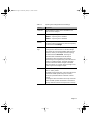
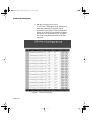
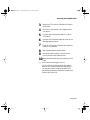
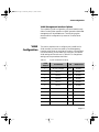
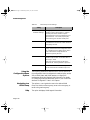
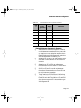
Table 5-3 provides an overview of each Configuration Menu
item.
Table 5-3
Configuration Menu Options
Menu Item
Description
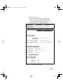
System Administration
Configuration
Displays and allows you to change the name,
location, and contact information for the
IntraSwitch.
See “System Administration Configuration” on
page 5-9.
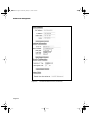
Switch IP Configuration
Displays and allows you to change the
information needed to access the IntraSwitch
over the network (in-band management).
See “System IP Configuration” on page 5-10.
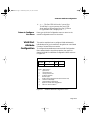
Bootstrap Configuration
Allows you to change the boot method the
IntraSwitch uses for loading its software. Also
allows you to change the parameters used for
downloading a new version of runtime
software for the IntraSwitch.
See “Bootstrap Configuration” on page 5-12.
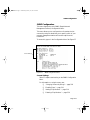
SNMP Configuration
Displays and allows you to change the
IntraSwitch’s SNMP (Simple Network
Management Protocol) parameters; such as,
read/write community strings, trap
authentication, and trap receivers.
See “SNMP Configuration” on page 5-17.
Port Configuration
Allows you to manually configure each of the
IntraSwitch’s ports for speed, connection, link
mode, and auto-negotiation. Also displays an
overall status of the IntraSwitch system.
See “Port Configuration” on page 5-20.
Spanning Tree Configuration
Displays and allows you to change the
IntraSwitch’s Spanning Tree parameters.
See “Spanning Tree Configuration” on page
5-27.
Forwarding DB/Security
Configuration
Allows you to view and search for addresses in
the IntraSwitch’s MAC Forwarding Table. Also
allows you to set a trap for duplicate IP
addresses and view the trap log.
See “Forwarding Database/Security
Configuration” on page 5-27.
Page 5-7
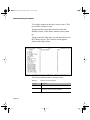
6216M Book Page 8 Wednesday, January 27, 1999 5:26 PM
Console Management
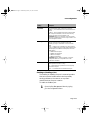
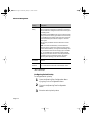
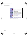
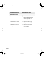
Menu Item
Description
TFTP Image File
Downloading Configuration
Allows you to upgrade the IntraSwitch’s
software.
See “TFTP Image File Downloading
Configuration” on page 5-33.
System Reset Options
Allows you to reset the IntraSwitch by
performing a “warm” reboot. Also allows you
to set the IntraSwitch for an automatic reset
(up to 24 hours) in advance.
See “System Reset Options” on page 5-39.
Page 5-8
System Log
Allows you to view the IntraSwitch’s System
Log.
See “System Log” on page 5-42.
Set Idle Time-out
Allows you to set the idle time-out period when
using Console and Telnet to access the
IntraSwitch.
See “Idle Time-out” on page 5-44.
Change Password
Allows you to change the password needed to
access the Configuration Menu.
See “Changing the Password” on page 5-46.
Global Port Configuration
Allows you to change the configuration of all
ports simultaneously.
Return to Previous Menu
Exits the Configuration Menu and returns to
the Local Management Interface Main Menu.
6216M Book Page 9 Wednesday, January 27, 1999 5:26 PM
Configuration Menu
System Administration Configuration
This menu displays and allows you to change the IntraSwitch’s
name, location, and contact information.
To access the System Administration Configuration Menu, type
a in the Configuration Menu. A screen similar to Figure 5-4
appears.
Current Settings
Figure 5-4
System Administration Configuration Menu
Current Settings
Table 5-4 explains each setting on the System
Administration Configuration Menu.
For information on using the menu, see:
❏ “Changing System Administration Information” — page 5-10.
Table 5-4
System Administration Configuration Menu Settings
Menu Item
Description
Switch Name
The name of the IntraSwitch (up to 64 characters,
including spaces).
Switch Location
The location where the IntraSwitch is physically located
(up to 64 characters, including spaces).
Switch Contact
The name of the person or entity responsible for the
IntraSwitch (up to 64 characters, including spaces).
Page 5-9
6216M Book Page 10 Wednesday, January 27, 1999 5:26 PM
Console Management
Changing System Administration Information
To change the IntraSwitch’s name, location, or contact
information:
1
Open the System Administration Configuration Menu by typing a in the Configuration
Menu.
2
Type the command letter of the item to be
changed in the System Administration Configuration Menu.
3
Type the information at the prompt.
See Table 5-4 for a description of each parameter.
∆
Note: Each parameter is limited to 64 characters, including spaces.
To cancel a selected option, press ctrl-cat
the command prompt.
4
Press Return
.
The IntraSwitch’s system administration
information is changed.
To quit and return to the Configuration
Menu, type q.
System IP Configuration
This menu displays and allows you to change the information
needed to access the IntraSwitch over the network via in-band
management.
To access the System IP Configuration Menu, type i in the
Configuration Menu. A screen similar to Figure 5-5 appears.
Page 5-10
6216M Book Page 11 Wednesday, January 27, 1999 5:26 PM
System IP Configuration
.
Current Settings
Figure 5-5
▲
System IP Configuration Menu
Important: By default, each address is set
to 0.0.0.0.
Current Settings
Table 5-5 explains each setting on the System IP
Configuration Menu.
For information on using the menu, see “Changing System
IP Information” on page 5-12.
Table 5-5
System IP Configuration Menu Settings
Setting
Description
Switch IP Address
The IntraSwitch’s IP (Internet Protocol) address.
Switch Subnet
Mask
The IntraSwitch’s subnet mask.
Switch Default
Router
The address of the IntraSwitch’s default router.
Page 5-11
6216M Book Page 12 Wednesday, January 27, 1999 5:26 PM
Console Management
Changing System IP Information
To change the IntraSwitch’s IP address, subnet mask, or
default router information:
1
Open the System IP Configuration Menu by
typing i in the Configuration Menu.
2
Type the command letter of the option you
want to change.
3
Type the new address at the prompt.
See Table 5-5 for a description of each
address.
▲
Important! Follow the format: number. number. number. number.
To cancel, press ctrl-cat the command
prompt.
4
Press Return
.
The IntraSwitch’s IP information is changed.
To quit and return to the Configuration
Menu, type q.
Bootstrap Configuration
This menu displays (and allows you to change) the bootstrap
parameters used for loading the IntraSwitch’s software at
startup, and for downloading a new version of software when
one is issued.To access the Bootstrap Configuration Menu, type
b in the Configuration Menu. A screen similar to Figure 5-6
appears.
Page 5-12
6216M Book Page 13 Wednesday, January 27, 1999 5:26 PM
Bootstrap Configuration
Current Settings
Figure 5-6
▲
BootStrap Configuration Menu
Important! The IntraSwitch’s default Load
Mode setting is Local.
When the IntraSwitch is powered on, it loads its software via
one of two methods: locally (via its internal flash memory
which is the default setting) or remotely over the network.
Image Banks
The IntraSwitch has two banks to store its run time software.
The banks are referred to as bank 1 and bank 2.
Either of these banks may be the Boot Bank, which is the bank
where the runtime code will be loaded the next time the
IntraSwitch is booted.
When downloading new runtime image codes, the user may
specify either of the two banks as the Destination Bank in
which the new code will be loaded.
Page 5-13
6216M Book Page 14 Wednesday, January 27, 1999 5:26 PM
Console Management
Current Settings
Table 5-6 explains each setting on the Bootstrap
Configuration Menu.
For information on using the menu, see:
❏ “Loading Software Locally” — page 5-15
❏ “Loading Software Remotely” — page 5-16
▲
Table 5-6
Page 5-14
Important! For information on performing a software upgrade, see “Performing a
Software Upgrade” on page 5-35.
Bootstrap Configuration Menu Settings
Setting
Description
Running Image
Version/Date
The version and compilation date of runtime code that is
currently running on the IntraSwitch.
Bank 1 Image
Version/Date
The version and compilation date of runtime code that is
stored in Bank 1.
Bank 2 Image
Version/Date
The version and compilation date of runtime code that is
stored in Bank 2.
Boot Server IP
The IP address of the boot server providing BootP/TFTP
capabilities on your network.
Boot File Name
The name of the IntraSwitch’s software file and its
network path.
Boot Mode
The method for requesting the software image file from
the network.
BootP-TFTP — Sets the IntraSwitch to request an IP
address from a BootP server AND to download the
software’s image file through TFTP (Trivial File Transfer
Protocol).
▲ Important! To use this option, the IntraSwitch’s IP
address must be set to 0.0.0.0 and the Load Mode must
be set to Remote.
TFTP ONLY — Sets the IntraSwitch to only download the
software image file through TFTP.
▲ Important! To use this option, the IntraSwitch must
already have an assigned IP address and the Load Mode
must be set to Remote.
6216M Book Page 15 Wednesday, January 27, 1999 5:26 PM
Bootstrap Configuration
Setting
Description
Load Mode
The current method for loading the IntraSwitch’s
software.
Local — Executes the software image file from the
IntraSwitch’s internal flash memory (default setting; the
IntraSwitch automatically reverts to this setting after
downloading a new software file).
Remote — Loads the software image file from a server
on the network.
▲ Important! To use the remote option, you must
select BootP-TFTP or TFTP as the Boot Mode.
Boot Bank
The number of the image bank being used to load the
IntraSwitch’s software.
Note: The image bank is where the runtime code is
stored; the IntraSwitch has two image banks: Boot Bank
and Destination Bank.
Selecting the Boot Bank Number
To select the Boot Bank that the IntraSwitch will boot from
the next time it boots up:
1
Open the Bootstrap Configuration Menu by
typing b in the Configuration Menu.
2
Type a in the Bootstrap Configuration Menu
to toggle the Boot Bank from 1 to 2 (or vice
versa).
Loading Software Locally
The IntraSwitch will always boot locally unless the user sets
it to boot load remotely. It would then download the new
image code and reset to load locally.
1
Make sure the IntraSwitch is configured with
a valid IP address.
2
Open the Bootstrap Configuration Menu by
typing b in the Configuration Menu.
3
Type l in the Bootstrap Configuration Menu
to set the Load Mode to Local.
Page 5-15
6216M Book Page 16 Wednesday, January 27, 1999 5:26 PM
Console Management
The IntraSwitch is set to load software locally
from its flash memory.This occurs whenever
the unit is powered on or reset.
Loading Software Remotely
To set the IntraSwitch to (download its software) over the
network from a remote server:
Page 5-16
1
Open the Bootstrap Configuration Menu by
typing b in the Configuration Menu.
2
Type s in the Bootstrap Configuration Menu,
select option Set Boot Server IP Address
.
3
Type the IP address at the prompt of the
remote boot server which contains the unit’s
software image file, then press Return
.
4
5
6
Type r to set the Load Mode to Remote
.
7
Press Return
.
The unit is set to download its software
remotely from the network.This will occur
the next time the unit is powered on or reset.
Type f to select the option Set File Name
.
Type the software’s file name and network
path at the prompt.
6216M Book Page 17 Wednesday, January 27, 1999 5:26 PM
SNMP Configuration
SNMP Configuration
This menu displays the unit’s SNMP (Simple Network
Management Protocol) Configuration Menu.
This menu allows you to configure the unit’s read and write
community strings. It also allows you to specify which of your
network management stations will receive traps from the
IntraSwitch.
To access this, type n in the Configuration Menu. See Figure 5-7
.
Current Settings
Figure 5-7
SNMP Configuration Menu
Current Settings
Table 5-7 explains each setting on the SNMP Configuration
Menu.
For information on using the menu, see:
❏
“Changing Community Strings” — page 5-18
❏ “Enabling Traps” — page 5-19
❏ “Adding a Trap Receiver” — page 5-19
❏ “Deleting a Trap Receiver” — page 5-20
Page 5-17
6216M Book Page 18 Wednesday, January 27, 1999 5:26 PM
Console Management
Table 5-7
SNMP Configuration Menu Settings
Setting
Description
SNMP Read
Community
The IntraSwitch’s SNMP read community string.
Note: The read community string is a single word that
defines access rights for reading SNMP data objects.
The default setting is public.
SNMP Write
Community
The IntraSwitch’s SNMP write community string.
Note: The write community string is a single word that
defines access rights for writing SNMP data objects.
The default setting is private.
Trap
Authentication
The status of the SNMP agent to generate authentication
traps.
The default setting is disabled.
SNMP Trap
Receivers
The IP addresses of the network management stations
that can receive traps from the IntraSwitch.
Normally, these addresses are the same as your network
management software systems’ IP address(es).
▲ Important! A maximum of four trap receivers is
allowed.
Changing Community Strings
To change the IntraSwitch’s community strings:
Page 5-18
1
Open the SNMP Configuration Menu by typing n in the Configuration Menu.
2
Type r to change the read community string
or w to change the write community string.
3
Type a new community string at the prompt.
See Table 5-7 for a description of read and
write community strings.
To cancel a selected option, press ctrl-cat
the command prompt.
4
Press Return
.
To quit and return to the Configuration
Menu, type q.
6216M Book Page 19 Wednesday, January 27, 1999 5:26 PM
SNMP Configuration
Enabling Authentication Traps
The IntraSwitch can be set to generate authentication traps.
Authentication traps are messages sent across the network
to an SNMP network management station.They alert you
when someone without access rights attempts to change
the device’s MIB information.
To set the IntraSwitch to generate traps:
1
Open the SNMP Configuration Menu by typing n in the Configuration Menu.
2
Type t toggle trap authentication from disabled to enabled
.
To cancel, press ctrl-cat the command
prompt.
To quit and return to the Configuration
Menu, type q.
Adding a Trap Receiver
Trap receivers are the network management stations
designated to receive traps from the IntraSwitch when they
occur.
▲
Important! The maximum number of
trap receivers that can be set is four.
To add a trap receiver entry:
1
Open the SNMP Configuration Menu by typing n in the Configuration Menu.
2
3
Type a to Add a Trap Receiver
.
4
Type the trap receiver’s community string at
the prompt, then press Return
.
Type the IP address of the network management station you want to receive traps, then
press Return
.
To cancel, press ctrl-c.
Page 5-19
6216M Book Page 20 Wednesday, January 27, 1999 5:26 PM
Console Management
The trap receiver entry is added.
To return to the Configuration Menu, type q.
Deleting a Trap Receiver
To delete a trap receiver entry:
1
Open the SNMP Configuration Menu by typing n in the Configuration Menu.
2
3
Type d to Delete a Trap Receiver
.
Type the number of the receiving network
management station entry to be deleted,
then press Return
.
The trap receiver entry is deleted.
To return to the Configuration Menu, type q.
Port Configuration
This menu allows you to manually configure each of the
IntraSwitch’s ports and any installed MII expansion modules for
speed, connection, link mode, and auto-negotiation.
It also provides an overview of the entire IntraSwitch system’s
port operating status.The Advanced Port Configuration option
“v” allows you to configure ports BC filtering and its autonegotiation advertisement.
The default parameters for each of the IntraSwitch’s ports are:
❏
auto-negotiation — enabled; auto-negotiates to
10 or 100Mbps half or full duplex
To access the Port Configuration Menu, type p in the
Configuration Menu. A screen similar to Figure 5-9 appears.
Page 5-20
6216M Book Page 21 Wednesday, January 27, 1999 5:26 PM
Port Configuration
.
IntraSwitch System
Information
Current Port Settings
Figure 5-8
Port Configuration Menu
Figure 5-9
Advanced Port Configuration Menu
Page 5-21
6216M Book Page 22 Wednesday, January 27, 1999 5:26 PM
Console Management
IntraSwitch System Information
Table 5-8 on page 5-22 explains the system information.
For directions on using this menu to view IntraSwitch
system information, see “Viewing IntraSwitch System
Information” on page 6-4.
Current Port Settings
The current port for which statistics are displayed is shown
at the top of the screen next to “Port Number:
”.
Table 5-8 explains each setting on the Port Configuration
Menu.
For information on using the Port Configuration Menu, see:
❏ “Enabling/Disabling a Port” — page 5-23
❏ “Configuring Duplex Mode” — page 5-24
❏ “Configuring Auto Negotiation” — page 5-25
Table 5-8
Page 5-22
Port Management Menu Settings
Setting
Description
Port Operating
Status
The status of the IntraSwitch. This field displays symbols
for each of the unit’s 16 ports.
List of Port Symbols:
X — no port exists.
- (negative symbol) — a port exists but is not linked.
! — the port is disabled.
B — the port is in a blocking state.
S — the port is in a listening state.
R — the port is in a learning state.
+ — the port is in a forwarding state.
▲ Important! Type h “Help for Legends” in the Port
Management Menu for a list of the port symbols.
Port Number
The port number for which parameters are shown.
BC Filter
The port’s capability to forward broadcast packets.
Enabled — broadcast packets will be discarded.
Disabled — broadcast packets will be processed
normally.
6216M Book Page 23 Wednesday, January 27, 1999 5:26 PM
Port Configuration
Setting
Description
Port Status
The administrative status of the port’s connection.
Enabled — port is enabled and can receive and forward
packets.
Disabled — port is disabled and cannot receive packets.
Note: If the port is disabled, it cannot not receive any
packets, even if the port’s Link Status is UP.
▲ Important! There is no indication on the front panel
that a port is disabled. The ports can only be seen in one
of the management modes. .
Auto-Neg
The status of the port’s auto-negotiation capability. This
field also shows the port’s speed and link mode
capability by using a combination of four characters:
ABCD.
ABCD — capable of all combinations of speed and link
mode (i.e., 100Base-TX full and half duplex, 10Base-T full
and half duplex, and 10Base-T half duplex). This is the
default setting.
A — 100Base-TX full duplex
B — 100Base-TX half duplex
C — 10Base-T full duplex
D — 10Base-T half-duplex
▲ Important! Type h “Help for Legends” in the Port
Configuration Menu for a complete list of all the
combinations available.
Link Status
The status of a network device’s connection to the port
and the speed and mode it is using.
Up — a network device is powered on and is properly
connected to the port.
Down — no network device connected to the port.
Enabling or Disabling a Port
The enabling or disabling of a port is a manual operation
that can be used to isolate network devices possibly
causing problems on the network or to prevent
unauthorized use of a port or station.
To enable or disable a port:
1
Open the Port Management Menu by typing
p in the Configuration Menu.
Page 5-23
6216M Book Page 24 Wednesday, January 27, 1999 5:26 PM
Console Management
2
Select the port to be enabled or disabled by
typing s, entering the port’s number, and
pressing Return
.
3
Type e to toggle the port’s connection to
enabledor disabled
, as desired.
The port’s status is changed. The new status
is displayed at the top of the screen next to
Port Status:
.
Configuring Duplex Mode
Full duplex mode allows a port to transmit and receive at
the same time.
▲
Important! To use full duplex mode, the
device to which the port is connected must support and be configured for full duplex mode.
∆
Page 5-24
Note: To configure a port for duplex mode,
first disable auto-negotiation, as described in
the next section.
1
Open the Port Management Menu by typing
p on the Configuration Menu.
2
Select the port to be configured for full
duplex mode by typing s, entering the port’s
number, and pressing Return
.
3
Type d to toggle the port’s duplex mode half to
full, or full to half.
The port’s mode is changed and is displayed
at the top of the screen next to Link Status
.
6216M Book Page 25 Wednesday, January 27, 1999 5:26 PM
Port Configuration
Configuring Auto-negotiation
Auto-negotiation is a feature of the Fast Ethernet standard
that enables two devices on a common segment to
communicate their capabilities.This feature allows the
devices to determine their highest common speed and best
communication parameters.
Options Negotiated
The options negotiated during auto-negotiation are:
❏ 100Base-TX Fast Ethernet or 10Base-T Ethernet)
❏ Duplex mode (full or half)
▲
Important! By default, all of the IntraSwitch’s
ports are set to full auto-negotiation.
Configuring an IntraSwitch’s Port for Auto-negotiation:
1
Open the Port Management Menu by typing
p in the Configuration Menu.
2
Select the port to be enabled/disabled by typing s, enter the port number. Press Return
.
3
Type a to toggle the port’s auto-negotiation
status to enabled
.
Auto-negotiation is changed and displayed at
the top of the screen next to Auto-Neg:
.
Setting Broadcast (BC) Filtering
1
To configure the BC filter, type v in the Port
Configuration Menu.The Advance Port Configuration Menu will appear on the screen.
2
Type o in the Advanced Port Configuration
Menu to toggle the BC filter option for the
port.
Page 5-25
6216M Book Page 26 Wednesday, January 27, 1999 5:26 PM
Console Management
3
If the desired operation is BC filter enabling,
press y at the confirmation prompt, or press
n to cancel the operation.
The BC filter for the selected port is toggled.
Modifying Auto-negotiation Advertisement
1
To modify the auto-negotiation advertisement for a port,Type v in the Port Configuration Menu.The Advanced Port Configuration
Menu appears on the screen.
2
type v in the Advanced Port Configuration
Menu to modify the port’s auto-negotiation
advertisement.
3
Enter any combination of [ABCD] at the
prompt.The user can select individual or any
other combination with the available four
options.
4
Press Return
.
The port’s auto-negotiation advertisement is
changed to the requested values.
∆
Note: The options s, n, and p on the
Advanced Port Configuration Menu bring up
the desired port.
Type q to return to the previous menu after
completing the configuration
Page 5-26
6216M Book Page 27 Wednesday, January 27, 1999 5:26 PM
Spanning Tree Configuration
Spanning Tree Configuration
This menu allows you to view and configure the IntraSwitch’s
Spanning Tree parameters.
The unit is shipped with Spanning Tree enabledon all ports.
You cannot disable Spanning Tree on an individual port basis.
See Chapter 7, “Advanced Management” for use of this menu to
configure the Spanning Tree Protocol.
Forwarding Database/Security Configuration
This menu allows the user to view and search for addresses in
the IntraSwitch’s MAC Forwarding Table. It also provides the
option for displaying MAC addresses and IP/MAC binding by
individual port.
The MAC Forwarding Table is a table of node addresses that the
IntraSwitch automatically builds by "listening and learning," It
performs this task by monitoring the packets that pass through
the IntraSwitch, checking the source and destination addresses,
and then recording the source address information in the table.
The IntraSwitch uses the information in this table to decide
whether a frame should be forwarded to a particular
destination port or “flooded” to all the ports other than the
received port. Each entry consists of the MAC address of the
device and an identifier for the port on which it was received.
∆ Note: The MAC address table can hold a
maximum of 8,192 entries.
To access the Forwarding DB/Security Configuration Menu,
type f in the Configuration Menu. A screen similar to Figure 510 appears.
Page 5-27
6216M Book Page 28 Wednesday, January 27, 1999 5:26 PM
Console Management
Current Settings
Figure 5-10
Forwarding DB/Security Configuration Menu
Current Settings
Table 5-9 explains each setting on the Forwarding DB/
Security Configuration Menu.
For information on using the menu, see:
❏ “Displaying the MAC Address Table” — page 5-29
❏ “Searching the MAC Address Table” —
page 5-30
❏ “Setting the MAC Address Age-Out Time” —
page 5-31
❏ “Enabling the Duplicated-IP Trap” —
page 5-32
❏ “Viewing the Trap Log” — page 5-32
Page 5-28
6216M Book Page 29 Wednesday, January 27, 1999 5:26 PM
Forwarding Database/Security Configuration
Table 5-9
Security Configuration Menu Settings
Setting
Description
DuplicatedIP Trap
The status of the Duplicated-IP Trap.
Enabled — IntraSwitch logs the duplicate IP address along with
the owner and spoofer MAC address in the trap log which can be
displayed using the l command in the Forwarding Database/
Security Configuration menu, and also sends a trap to the
receiving trap stations if a duplicate IP address is detected.
Disabled — the duplicate-IP Trap is disabled. The IntraSwitch does
NOT send a trap if a duplicate IP address is detected.
Age-Out
Time
The current age-out time for retaining addresses in the table (the
default is 300 seconds).
This is the number of seconds an address remains in the table
after it is learned by the IntraSwitch.
MAC
Address
Count
The number of entries currently in the MAC Address Table.
IP Address
Count
The number of entries in the MAC Address Table that contain a
corresponding IP address.
Displaying the MAC Address Table
The MAC address table can be displayed with or without IP
addresses. To view the MAC address table:
1
Open the Forwarding DB/Security Configuration
Menu by typing f in the Configuration Menu.
2
Type f to display the MAC address table with
MAC addresses and corresponding ports.
Type i to display the MAC address table with
MAC addresses, their corresponding IP
addresses, and corresponding ports.
∆ Note: The Agefield in the MAC address
table is the time to be aged of
outthe
entries.
∆ Note: Selfin the port number column represents the Switch MAC address and IP
address.
Page 5-29
6216M Book Page 30 Wednesday, January 27, 1999 5:26 PM
Console Management
Figure 5-11
Display Forwarding Database Menu
3
4
View the information that is displayed.
5
Type d and then the port number to display
MAC address learned on a port. Enter port
Number next to Enter Port Number:
prompt and press Return
.This displays the
MAC address on this port.
6
Type b and then the port number to display
MAC/IP binding on a port. Enter port number next to Enter Port Number:
prompt
and press Return
.This displays the IP/MAC
binding on this port.
Press any key to exit the MAC address table
and return to the Forwarding DB/Security
Configuration Menu.
Searching the MAC Address Table
The MAC address table can be searched by MAC address or
by IP address. To search the MAC address table for a
specific MAC address or an IP address:
Page 5-30
1
Open the Forwarding DB/Security Configuration
Menu by typing f in the Configuration Menu.
2
Type a to search for a MAC address.
Type p to search for an IP address.
6216M Book Page 31 Wednesday, January 27, 1999 5:26 PM
Forwarding Database/Security Configuration
3
Type the MAC address or the IP address you
want to search for at the prompt.
4
Press Return
.
The address, if located, is displayed. If the address
is not located, a message appears stating so.
Setting the MAC Address Age-Out Time
This option sets the Age-Out Time for the MAC Forwarding
Table.
The Age-Out Time is the number of seconds that addresses
remain in the table after being learned by the IntraSwitch.
The default is 300seconds.
To set the MAC address Age-Out Time:
1
Open the Forwarding DB/Security Configuration
Menu by typing f in the Configuration Menu.
2
3
Type o to set the MAC Address Age-Out Time.
4
Press Return
.
The MAC Address Age-Out Time is changed
and is displayed at the top of the screen next
to “Age-Out Time
.”
Enter the new Age-Out time (in seconds) at
the prompt.
Page 5-31
6216M Book Page 32 Wednesday, January 27, 1999 5:26 PM
Console Management
Enabling the Duplicated-IP Trap
The IntraSwitch logs the duplicate IP address along with the
owner and spoofer MAC address in the trap log which can be
displayed using the l command in the Forwarding Database
Security Configuration menu, and also sends a trap to the
receiving trap stations if a duplicate IP address is detected.
To enable the Duplicated-IP Trap:
1
Open the Forwarding DB/Security Configuration
Menu by typing f in the Configuration Menu.
2
Type t to toggle the Duplicated-IP Trap to
enabled
.
The Duplicate-IP Trap is enabled. Its status
appears at the top of the screen next to
“Duplicate-IP Trap:
.”
Viewing the Trap Log
The trap log displays all of the traps that the IntraSwitch has
generated since the last time the log was cleared.
∆ Note: The trap log holds a maximum of 128
entries.
Page 5-32
1
Open the Forwarding DB/Security Configuration
Menu by typing f in the Configuration Menu.
2
Type l to display the trap log.
The trap log appears, displaying the last 128
traps the IntraSwitch has generated (or the
number of traps the IntraSwitch has generated since the last time the log was cleared).
3
Press any key on your keyboard to exit the
trap log and return to the Security Configuration Menu.
6216M Book Page 33 Wednesday, January 27, 1999 5:26 PM
Image File Downloading Configuration
4
To clear the log, type c in the Security Configuration Menu.
Image File Downloading Configuration
Current Settings
Typing g in the Configuration Menu allows the user to select
the Image File Downloading Configuration Menu.
Figure 5-12
Image File Downloading Configuration Menu
This menu allows you to select the type of download action.
The option “t” takes you to In-band TFTP downloading option
and the “x” option takes you to the serial download option.
When Asanté issues a new version of software for the
IntraSwitch, you can obtain it from Asanté’s Word Wide Web site
or by contacting Asanté’s Technical Support (see Appendix C,
“Technical Support”).
Image Downloading Through TFTP
To download a new image file In-band through TFTP, type t in
the Image Download Configuration Menu (option g in
Configuration Menu). A screen similar to Figure 5-13 appears.
Page 5-33
6216M Book Page 34 Wednesday, January 27, 1999 5:26 PM
Console Management
.
Figure 5-13
Image Downloading Menu
Current Settings
Table 5-10 explains each setting on the Image Downloading
Menu. For information on using the menu, see:
❏ “Performing a Software Upgrade at Runtime” on
page 5-35.
Table 5-10
Page 5-34
Image Downloading Menu Settings
Setting
Description
Running Image
Version/Date
The version and compilation date of runtime code that is
currently running on the IntraSwitch. This should be the
same as the Boot Bank.
Bank 1 Image
Version/Date
The version and compilation date of runtime code that is
stored in Bank 1.
Bank 2 Image
Version/Date
The version and compilation date of runtime code that is
stored in Bank 2.
6216M Book Page 35 Wednesday, January 27, 1999 5:26 PM
Image Downloading Through TFTP
Setting
Description
Protocol
The current method being used to download a software
image file from the network.
This protocol is always set to TFTP.
Image Server IP
The IP address of the network server containing the
IntraSwitch’s software image file.
Image File Name
The software image file’s name and network path.
Retry Count
The number of attempts the IntraSwitch makes to
download the image file.
Destination Bank
The number of the destination bank to where the
software file will be downloaded and stored.
Performing a Software Upgrade at Runtime
The software image file must be downloaded from a
network management station on your network that
contains capabilities.
To upgrade the IntraSwitch’s software:
▲
Important!
Make sure the IntraSwitch is configured with an IP address.
1
Open the TFTP Image File Downloading
Configuration
Menu by typing t in the
Image File Downloading Configuration
Menu.
2
3
Type s to set the Image Server Address
.
4
5
Type f to set the Image File Name
.
6
Type c to set the Retry Count
.
Enter the IP address of the server containing the
image file at the prompt, then press Return
.
Enter the image file’s name and network path
at the prompt, then press Return
.
Page 5-35
6216M Book Page 36 Wednesday, January 27, 1999 5:26 PM
Console Management
7
Enter the number of attempts the IntraSwitch
will make to download the file, then press
Return
.
8
Select the Destination Image Bank through the a
option.
9
Type d to Download the ImagetoFile
the
Destination Bank (this option allows you to
change the boot bank at a later time and use
the Reset Menu to schedule a reset, at which
time the new software will be used).
or
Type b to Download the Image File and
Resetthe IntraSwitch (this option immediately boots the IntraSwitch with the new version of software).
10 Type q to return to the Configuration menu.
Serial Downloading Configuration
This menu allows you to download a new software image
file for the IntraSwitch without interrupting the current
operation.
To download a new image through the IntraSwitch’s serial
port, type x in the Image File Download Configuration
Menu.The following screen appears.
Page 5-36
6216M Book Page 37 Wednesday, January 27, 1999 5:26 PM
Serial Downloading Configuration
Figure 5-14
X/Y/ZModem Image File Downloading Menu
Current Settings
Table 5-11 explains each setting on the X/Y/Z Downloading
Menu.
Table 5-11
X/Y/Z Downloading Menu Table
Setting
Description
Download Protocol
The current setting of the serial download protocol that
IntraSwitch uses.
Current Baud Rate
The current baud rate of the IntraSwitch’s serial port.
Running Image
Version/Date
The version and compilation time of runtime code that is
currently running on IntraSwitch. This should be the
same as the Boot Bank.
Bank 1 Image
Version Date
The version and compilation date and time of runtime
code that is currently stored in Image Bank 1.
Bank 2 Image
Version Date
The version and compilation date and time of runtime
code that is currently stored in Image Bank 2.
Destination Bank
The number of the destination bank where the software
will be donwloaded and stored.
Download Protocol
Current serial download protocol.
Page 5-37
6216M Book Page 38 Wednesday, January 27, 1999 5:26 PM
Console Management
Setting
Description
Current Baud Rate
Current console baud rate.
Destination Bank
Current Destination Bank
Performing Software Upgrade
To upgrade the IntraSwitch’s software through its serial
port:
1
Open the X/Y/Z Modem Image Downloading
Menu.
2
Type x or y or z to select the corresponding
protocol.
3
Type c to select the console baud rate.The
Baud Rate Setting window appears as shown
in Figure 5-15.The maximum baud rate that
is currently supported is 57,600 bps.
Figure 5-15
Page 5-38
Setting Baud Rate
6216M Book Page 39 Wednesday, January 27, 1999 5:26 PM
System Reset Options
∆
∆
4
Select one of the options in the above screen
to select the required baud rate and confirm
it by typing y.
5
6
Type a to select the Destination Bank.
Use any serial communications software like
Procomm Plus, HyperTerminal, ZTerm, etc.,
to download the image file. Follow the
instruction manual of the serial communications software for file transfer instructions.
Note: The terminal on which serial communications software is running must have the same baud
rate as the Switch console baud rate.The connection between the terminal and the switch Console
port is RS232C straight-through cable.
7
Type d to download to the selected destination bank or b to download and reset.
8
Type q to return to the previous menu after
performing a successful download.
Note: The baud rate default for Console management is 9600 bps. If you select a baud rate for the
console port, other than 9600 bps, the screen will
display garbage data until the connected terminal
is set to the same baud rate as the console.
System Reset Options
The System Reset Options Menu allows you to reset the
IntraSwitch by performing a “warm” reboot. It also allows you
to schedule a reset up to 24 hours in advance.
To reset the IntraSwitch, type r in the Configuration Menu. A
screen similar to Figure 5-16 appears.
Page 5-39
6216M Book Page 40 Wednesday, January 27, 1999 5:26 PM
Console Management
.
Current Settings
Figure 5-16
Reset Menu
Current Settings
Reset menu settings are shown in the following table.
For information on using the menu, see:
❏
“Resetting the IntraSwitch” in Chapter 5
❏ “Scheduling a Reset” in Chapter 5
Page 5-40
Table 5-12
Reset Menu Settings
Setting
Description
Schedule Reset
Time
Number of seconds until the scheduled reset.
Cancel Reset
Cancels the scheduled reset.
Reset Switch
Resets the IntraSwitch immediately.
Reset Switch to
Factory Default
Resets the switch to factory default setting.
Reset Switch to
Factory Default
except IP&
bootstrap
Resets the IntraSwitch and its EEPROM to the factory
default without modifying the IP& Bootstrap
configuration.
6216M Book Page 41 Wednesday, January 27, 1999 5:26 PM
System Reset Options
Resetting the IntraSwitch
To reset the IntraSwitch:
∆
1
Open the Reset Menu by typing r in the Configuration Menu.
2
3
4
Type r to reset the IntraSwitch.
Type y to confirm the reset.
Type n to cancel the reset.
Note: Typing d will reset the IntraSwitch to the
factory default.Typing i will reset the IntraSwitch
to the factory default without affecting its IP and
Bootstrap configuration.
Scheduling a Reset
You can schedule the IntraSwitch to automatically perform
a reset from one second up to 24 hours (86,400 seconds) in
advance.
To schedule a reset:
1
Open the Reset Menu by typing r in the Configuration Menu.
2
Type s to schedule a reset time (within the
specified range).
3
Enter the number of seconds (within the
specified range) the IntraSwitch will wait
before it automatically resets.
▲
Important! The maximum number of seconds
that can be entered is 86400(24 hours).
Page 5-41
6216M Book Page 42 Wednesday, January 27, 1999 5:26 PM
Console Management
4
Press Return
.
The IntraSwitch is set to automatically reset
after the number of seconds that are specified elapse.
System Log
This menu allows you to view the IntraSwitch’s System Log.The
System Log records and displays any major system events
occurring on the IntraSwitch (such as a fatal error, etc.).
To view system log information, type l from the Configuration
Menu. A screen similar to Figure 5-17 appears.
Figure 5-17
System Log Menu
For information on using the menu, see:
❏ “Viewing the System Log” — page 5-42
❏ “Clearing the System Log” — page 5-43
Viewing the System Log
Page 5-42
1
Open the System Log Menu by typing l in the
Configuration Menu.
2
Type l to display the current system log.
A screen similar to Figure 5-18 appears.
6216M Book Page 43 Wednesday, January 27, 1999 5:26 PM
Configuration Menu
Figure 5-18
System Log Display
The system log displays any major system
events that have occurred on the
IntraSwitch.
If no major events have occurred,“System
up” messages are displayed.
∆ Note: The System Log holds a maximum of
64 entries.
3
Press any key on your keyboard to display
the next page of System Log information.
To exit this screen, press ctrl-c.
Clearing the System Log
1
Open the System Log Menu by typing l in the
Configuration Menu.
2
Type c to clear the current System Log.
The System Log is cleared.
Page 5-43
6216M Book Page 44 Wednesday, January 27, 1999 5:26 PM
Console Management
Set Menu Idle Time-out
The Set Menu Idle Time-out option allows the user to set the
Console User Interface Time-out and the Telnet User Interface
Time-out periods.
Typing t in the Configuration Menu brings up the following
screen:
Figure 5-19
IntraSwitch UI Time-out Configuration Screen
Current Settings
The following table explains the settings in the UI Time-out
Configuration Menu.
Page 5-44
Table 5-13
UI Time-out Settings
Setting
Description
Console UI Idle
Time-out
Duration of time the Console will remain idle before
returning to the main menu.
Telnet UI Idle Timeout
Duration of time the Console will remain idle before
closing the Telnet connection.
6216M Book Page 45 Wednesday, January 27, 1999 5:26 PM
Configuration Menu
To set the Console Idle Time-out Period
1
Type c in the UI Time-out Configuration Menu.
The current menu idle time-out is displayed in
minutes, as shown below.
.
Figure 5-20
2
Current Idle Time-out command line
Enter the Idle Time-out in minutes at the
prompt.
∆ Note:
The default time-out is 5 minutes.
To exit this option without making any changes,
press ctrl-c.
3
Press Return
.
The Console Idle Time-out period is changed.
To set the Telnet Idle Time-out period:
1
Type t in the UI Time-out Configuration Menu.
The current telnet idle time-out is displayed in
minutes, as shown below.
Figure 5-21 Telnet Idle Time-out period
2
Enter the Idle Time-out in minutes at the
prompt.
∆ Note:
The default time-out is 5 minutes.
To exit this option without making any changes,
press ctrl-c.
Page 5-45
6216M Book Page 46 Wednesday, January 27, 1999 5:26 PM
Console Management
3
Press Return
.
The Telnet Idle Time-out Period is changed.
After configuring the desired time-outs, type q to return to the
previous menu.
Changing the Password
The Change Password option allows you to change the
password needed to access the Configuration Menu.
▲
Important
! The factory default password is
Asante
. The password is case--sensitive.
To change the current Local Management Interface (Console)
password:
1
2
3
Type c in the Configuration Menu.
Type current password at the prompt.
Type a new password at the “Enter Current Password” prompt.
▲
4
5
Important
: The password is case-sensitive. The password must be a minimum of
one character and a maximum of 20 characters in length. The password takes any
ASCII code.
Press Return
.
Type the new password again at the confirmation password prompt.
To cancel this change, type ctrl-c.
6
Press Return
.
The password is changed.
Type q to return to the Configuration Menu.
Page 5-46
6216M Book Page 47 Wednesday, January 27, 1999 5:26 PM
Configuration Menu
Global Port Configuration
The Global Port Configuration option allows the user to change
the configuration information for all ports simultaneously, and
to change the configuration information of a single port if
necessary.This feature is helpful in cases where the user wants
the same configuration for all or any one port
The option o in the Configuration Menu will bring up the
Global Port Configuration menu.
Figure 5-22
Global Port Configuration Menu
Current Settings
The following table explains the current settings.
Table 5-14
Global Port Configuration Settings
Setting
Description
Port Operating Status
Reflects the System ports’ operating status.
Port Auto-negotiation
Reflects the System ports’ current autonegotiation enable/disable information.
Note: For MII-FX and MII-FL, there is no autonegotiation, and hence their auto-negotiation
is displayed as “-”.
Port Speed/Duplex
Reflects the System ports’ current speed and
duplex information.
Page 5-47
6216M Book Page 48 Wednesday, January 27, 1999 5:26 PM
Console Management
Global Configuration Operations
1
Type h to view the help screen which displays
the meaning of the symbols in the Current Setting.
Figure 5-23
Page 5-48
Global Port Configuration Help Menu
2
Type e to enable auto-negotiation for all ports
simultaneously.
3
Type d to enable auto-negotiation for all ports
simultaneously.
4
Type t to set all ports to 10Mbps speed. If any of
the ports have auto-negotiation enabled, typing
this option prompts a Disable Global Auto-negotiation First message.This means this operation
will be effected only if auto-negotiation is disabled for all ports.
6216M Book Page 49 Wednesday, January 27, 1999 5:26 PM
Configuration Menu
5
Type u to set all ports to 100Mbps speed. If any
of the ports have auto-negotiation enabled, typing this option prompts a Disable Global Autonegotiation First message.This means this operation will be effected only if auto-negotiation is
disabled for all ports.
6
Type f to set all ports to full duplex mode. If any
of the ports have auto-negotiation enabled, typing this option prompts a Disable Global Autonegotiation First message.This means this operation will be effected only if auto-negotiation is
disabled for all ports.
7
Type l to set all ports to half-duplex mode. If any
of the ports have auto-negotiation enabled, typing this option prompts a Disable Global Autonegotiation First message.This means this operation will be effected only if auto-negotiation is
disabled for all ports.
8
Type v to modify all of the ports with the new
auto-negotiation advertisement.
∆ Note: All of the options above, except
option h, prompt for confirmation
. Press y
to confirm and n to cancel the operation.
9
Type a to view the current auto-negotiation
advertisement capability of all ports within the
system.
Page 5-49
6216M Book Page 50 Wednesday, January 27, 1999 5:26 PM
Console Management
Figure 5-24
Auto-negotiation Advertisement Summary Screen
Type p to select an individual port for configuration change.
Typing p prompts Enter port number>
message. Enter the
port number next to it.This will bring up the Port
Configuration Menu.
Statistics Menu
The Statistics menu displays current statistics for the
IntraSwitch on a per-port basis.The statistics displayed include
traffic, collisions, good frames, bad frames, and FCS errors.
∆ Note: See Chapter 6,“Status Monitoring,
Traffic, and Statistics” for information on using
this menu to view the IntraSwitch’s statistics.
Page 5-50
DRAFT
6216M Book Page 1 Wednesday, January 27, 1999 5:26 PM
6
Status Monitoring and
Statistics
This chapter describes how to view the IntraSwitch 6216M and
6224’s current operating information, system information, and
statistics.
This chapter contains the following sections:
❏
Viewing Current Operating Information
❏
Viewing IntraSwitch System Information
❏
Viewing Statistics
6216M Book Page 2 Wednesday, January 27, 1999 5:26 PM
Status Monitoring and Statistics
Monitoring the IntraSwitch
Viewing
Current
Operating
Information
The IntraSwitch’s current operating information can be viewed
by accessing the General Information Menu within the
IntraSwitch’s Local Management Interface.
To view the IntraSwitch’s current operating information:
1
Access the IntraSwitch’s Local Management
Interface.
∆
Note: See Chapter 4,“Setting Up For Management” for instructions on how to connect to the
Local Management Interface.
2
Type g in the Local Management Interface Main
Menu. A screen similar to Figure 6-1 appears:
Figure 6-1
General Information Menu
Table describes each parameter.To exit the General
Information Menu, press the space bar
on your keyboard.
Page 6-2
6216M Book Page 3 Wednesday, January 27, 1999 5:26 PM
Viewing Current Operating Information
Table 6-1
General Information Menu Parameters
Setting
Description
Running Image Version/Date
The version and compilation date of runtime
code that is currently running on the unit.
Bank 1 Image Version/Date
The version and compilation date of runtime
code that is stored in Bank 1.
Bank 2 Image Version/Date
The version and compilation date of runtime
code that is stored in Bank 2.
Switch Name
The name assigned to the IntraSwitch.
Switch Location
The physical location of the IntraSwitch.
Switch Contact
Name of the person responsible for the unit.
DRAM Size
The size, in megabytes (MB), of the unit’s
Dynamic Random Access Memory.
Flash Size
The size, in MB, of the IntraSwitch flash
memory. Flash memory is non-volatile RAM.
EEProm Size
Size, in kilobytes, of the unit’s EEPROM.
Console Baud Rate
The current setting of the console port’s baud
rate/speed.
MAC Address
The IntraSwitch’s hardware address.
Note: This address cannot be changed.
IP Address
The units’s IP (Internet Protocol) address.
Subnet Mask
The IntraSwitch’s IP subnet mask.
Router
The IP address of the default gateway router to
which the IntraSwitch belongs.
Boot Load Mode
The current method the unit is using to load
its software.
TFTP Server
The IP address of the TFTP server configured
for the IntraSwitch.
Boot File Name
The name and network path of the
IntraSwitch’s software file.
Page 6-3
6216M Book Page 4 Wednesday, January 27, 1999 5:26 PM
Status Monitoring and Statistics
Viewing
IntraSwitch
System
Information
You can view system information on the IntraSwitch, and any
installed expansion modules, by accessing the Port
Management Menu within the Local Management Interface.
See Chapter 4,“Setting Up For Management” for instructions on
how to connect to the Local Management Interface.To view
IntraSwitch system information:
1
Access the IntraSwitch’s Local Management
Interface.
2
Type c in the Local Management Interface Main
Menu to open the Configuration Menu.
The “Enter Password” prompt appears.
3
Type your password at the prompt, then press
Return
.
4
Type p to open the Port Configuration Menu. A
screen similar to Figure 6-2 appears.
Ports 9 – 16
Ports 1 – 8 (including MII Ports)
IntraSwitch System
Information
Figure 6-2
Page 6-4
Port Configuration Menu
6216M Book Page 5 Wednesday, January 27, 1999 5:26 PM
Viewing Statistics
The system information is displayed at the top
of the screen, as highlighted in Figure 6-2.The
following table describes the IntraSwitch system
information.
Table 6-2
IntraSwitch System Information
Setting
Description
Port Operating Status
The status of the IntraSwitch. This field displays
status symbols for each of the IntraSwitch’s ports.
Port Symbols:
X — no port exists (e.g., an Asanté MII module is
not installed in the expansion slot).
- (negative symbol) — a port exists but there is no
link on the port.
! — the port is disabled.
B — the port is in a blocking state.
S — the port is in a listening state.
R — the port is in a learning state.
+ — the port is in a forwarding state.
▲ Important! Type h “Help for Legends” in Port
Configuration Menu for a list of the port symbols.
Viewing
Statistics
Viewing statistics on a regular basis allows you to evaluate your
network’s performance.You can view current statistics for the
IntraSwitch on a per-port basis by accessing the Statistics Menu
in the Local Management Interface.
To view statistics:
1
Access the IntraSwitch’s Local Management
Interface.
∆
Note: See Chapter 4,“Setting Up For Management” for instructions on connecting to the Local
Management Interface.
2
Type s in the Local Management Interface Main
Menu.
A screen similar to Figure 6-3 appears:
Page 6-5
6216M Book Page 6 Wednesday, January 27, 1999 5:26 PM
Status Monitoring and Statistics
Figure 6-3
Statistics Menu
The received frames, transmitted frames, and error frames are
displayed on this screen.The following table describes statistics
fields on the statistics screen.
Table 6-3
Statistics Fields on Statistics Screen
Statistics
Description
Rx Frames
Total number of frames received on the port since
system up
Tx Frames
Total number of frames transmitted on the port
since system up.
Errors
Total number of frames that are received with errors
on this port since system up.
The error includes the following:
CRC error, Runt frames, Frame-too-long, Jabber
errors.
Page 6-6
6216M Book Page 7 Wednesday, January 27, 1999 5:26 PM
Viewing Statistics
Typing l brings up the screen which shows statistics since the
last reset.
Figure 6-4
Statistics Since Last Reset
The following table describes the fields in the Statististics Since
Last Reset Table.
Table 6-4
Statistics Since Last Reset
Statistics
Description
Rx Frames
Total number of frames received on the port since
last reset
Tx Frames
Total number of frames transmitted on the port
since last reset.
Errors
Total number of frames that are received with errors
on this port since last reset.
The error includes the following:
CRC error, Runt frames, Frame-to-long, Jabber
errors.
Page 6-7
6216M Book Page 8 Wednesday, January 27, 1999 5:26 PM
Status Monitoring and Statistics
To reset the counters in the above screen, type r. This
resets all the counters to zero.
Typing s on this screen takes the user back to the
Statistics Screen, which shows statistics since system
up.
Typing c on both of the above screens takes the user to
the Counters screen. The Counters screen appears
similar to the figure below.
Figure 6-5
Counters Screen
The following table describes the Counters screen.
Table 6-5
Page 6-8
Counters Screen Description
Statistics
Description
Rx Bytes
Total number of bytes received on a particular port.
Rx Frames
Total number of packets received on a particular port. This
includes broadcast and multicast packets.
6216M Book Page 9 Wednesday, January 27, 1999 5:26 PM
Viewing Statistics
Statistics
Description
Rx Dropped
Frames
Total number of frames that are dropped due to lack of
buffers on a particular port.
Tx Frames
Total number of transmitted frames on a particular port.
CRC Errors
Frame count received on a particular port that is an
integral number of octets but does not pass the FCS check.
Runts
Total number of frames shorter than 64 bytes received on a
particular port.
Frame Too Long
Total number of frames longer than 1518 bytes received on
a particular port.
Jabbers
Total number of frames received that were longer than
1518 bytes (excluding framing bits but including FCS
octets), and had either an FCS error or an alignment error
on a particular port.
Total Errors
Total number of error frames received on a particular port.
Collisions
Total number of collisions on a particular port.
Good Broadcast
Total number of good broadcast packets received on a
particular port.
Good Multicast
Total number of good multicast packets received on a
particular port.
64-Byte Frames
Total number of packets received whose length is 64 octets
(excluding framing bits but including FCS octets).
65-127 Frames
Total number of packets received whose length is between
65 and 127 octets (excluding framing bits but including
FCS octets).
128-255 Frames
Total number of packets received whose length is between
128 and 255 octets (excluding framing bits but including
FCS octets).
256-511 Frames
Total number of packets received whose length is between
256 and 511 octets (excluding framing bits but including
FCS octets).
512-1023 Frames
Total number of packets received whose length is between
512 and 1023 octets (excluding framing bits but including
FCS octets).
1024-1518
Frames
Total number of packets received whose length is between
1024 and 1518 octets (excluding framing bits but including
FCS octets).
Page 6-9
6216M Book Page 10 Wednesday, January 27, 1999 5:26 PM
Status Monitoring and Statistics
The Counters screen displays the above counters on a per port
basis.
Typing t on the Counters screen brings up the Statistics screen.
Typing q on the above screen brings up the previous menu
item.
∆
Page 6-10
Note: In the Statistics and Counters screens,
“Real-time” means total number of frames received
since system up time and “Rate” means the average
number per second.
DRAFT
6216M Book Page 1 Wednesday, January 27, 1999 5:26 PM
7
Advanced
Management
This chapter describes how to configure the Spanning Tree
Protocol on the IntraSwitch 6216M and 6224.
This chapter contains the following sections:
❏
Spanning Tree Protocol
❏
How it Works
❏
Enabling/Disabling STP
❏
Configuring STP Parameters
❏
Configuring STP Port Parameters
6216M Book Page 2 Wednesday, January 27, 1999 5:26 PM
Advanced Management
Advanced Management
Spanning Tree
Protocol
The Spanning Tree Protocol (STP) is a part of the IEEE 802.1d
bridge specification. It provides fault tolerance on a network
by detecting potential “bridged loops” and then removing them
by blocking the appropriate ports to other switches.
For example, in a large network with multiple paths, there is a
possibility that the same message will get broadcast all over the
network through multiple paths, resulting in a great amount of
extraneous network traffic, and possibly, network downtime.
This “closed path” or “bridged loop” among the networks could
be damaging because it could start an unending packet-passing
process.
With the Spanning Tree Protocol applied to the network, a path
between every pair of accessible nodes on the network is
mapped, ensuring that there are no loops in all of the network
paths.
∆
How it Works
Note: To explain STP more effectively, the
IntraSwitch is defined as a bridge in this
chapter.
The Spanning Tree Protocol requires the following:
❏
❏
Communication between all the bridges on the
network.
One bridge to start as a master, or Root Bridge
.
The communication between the bridges is carried out using
Bridge Protocol Data Units (BPDUs), which are transmitted in
packets with a known multicast address.
∆
Page 7-2
Note: BPDU packets provide information to
the Spanning Tree bridges about the configuration of the Spanning Tree network.
6216M Book Page 3 Wednesday, January 27, 1999 5:26 PM
Spanning Tree Protocol
The Root Bridge is a central point from which the network is
configured. It is selected on the basis of having the lowest
Bridge Identifier value
. This is a combination of the bridge’s
unique MAC address and a priority component defined for the
bridge.
The Root Bridge generates BPDUs on all ports at a regular
interval known as the Hello Time
. All other bridges in the
network have a Root Port. This is the port nearest to the Root
Bridge, and it is used for receiving the BPDUs initiated by the
Root Bridge.
Enabling/
Disabling STP
The IntraSwitch is shipped with Spanning Tree enabled on all
ports. It can be manually enabled or disabled following the
instructions below See Chapter 4,“Setting Up For Management”
for information on accessing the Local Management Interface.
To enable or disable STP on your IntraSwitch:
1
2
Access the Local Management Interface.
3
4
Type your password at the prompt.
5
Type t to toggle STP to enabledor disabled
.
If you select disabled
, you are prompted to
confirm the change.
Type c to open the Configuration Menu.The
“Enter Password” prompt appears.
Open the Spanning Tree Configuration Menu by
typing s in the Configuration Menu. See
Figure 7-1.
The STP status is changed.The status is displayed at the top of the screen next to STP Status.
For a description of the STP’s current settings,
see Table 7-1.
Page 7-3
6216M Book Page 4 Wednesday, January 27, 1999 5:26 PM
Advanced Management
.
Current Settings
Figure 7-1
Configuring STP
Parameters
Page 7-4
Spanning Tree Configuration Menu
The IntraSwitch is shipped with the following STP default
values:
❏
❏
❏
❏
❏
STP Status — enabled
Switch Priority — 0 x 8000
Maximum Age — 20 seconds
Hello Time — 2 seconds
Forward Delay — 15 seconds
▲
Important! You should NOT configure any
STP parameters unless you have knowledge and
experience with the IEEE 802.1d specification.
6216M Book Page 5 Wednesday, January 27, 1999 5:26 PM
Table 7-1
Spanning Tree Configuration Menu Settings
Setting
Description
Switch ID
The identification number of the IntraSwitch. This
value cannot be changed.
STP Status
The status of Spanning Tree on the IntraSwitch.
Enabled — Spanning Tree is enabled.
Disabled — Spanning Tree is disabled.
Switch
Priority
Maximum
Age
The priority value for this IntraSwitch switch.
The switch with the lowest priority value in a Spanning
Tree becomes the root bridge.
Determines how long the switch waits before trying to
re-configure the network when it is the Root Bridge.
If the switch has not received a BPDU within the time
specified, it will try to reconfigure the STP topology.
The default value is 20 seconds. The range of
permitted values is between 6 and 40 seconds.
Increasing the value of the Hello timer and the
Maximum Age timer together may reduce the amount
of traffic on a stable network. However, the bridge
processes information about changes to available
paths more slowly. As a result, when a change occurs,
it takes longer for the bridge to adjust.
Hello Time
Controls the frequency at which the switch sends a
BPDU or “hello” packet.
The default value is 2 seconds. (This causes the switch
to broadcast a BPDU packet every two seconds.)
The range of permitted values is between 1 and 10
seconds.
Increasing the value of the Hello timer may reduce the
number of BPDU packets transmitted on the network
and may make the network less responsive to change.
Page 7-5
6216M Book Page 6 Wednesday, January 27, 1999 5:26 PM
Advanced Management
Setting
Description
Forward
Delay
Controls the number of seconds a bridge must wait
before it changes a link from a listening to a learning
state and before it changes the link from a learning to a
forwarding state.
The default value is 15 seconds. (This means that after
a link [or the entire switch] goes down and connectivity
is re-established, the switch waits twice the amount of
the Forward Delay time before it begins to forward
traffic again.
The range of permitted values is between 4 and 30
seconds.
Note: A shorter Forward Delay value enables the
switch to recover a link more quickly but may reduce
overall network stability. A longer Forward Delay value
may prevent the switch from bringing up an unstable
link. An unstable link can threaten overall network
stability because each time the link changes between
forwarding and non-forwarding states, the entire
Spanning Tree topology must be recalculated.
Storm
Threshold
The threshold for detecting the BC* storm in the
network.
Storm
Duration
Controls the amount of time the switch sees the BC/
MC** traffic before it decides on the BC/MC storm.
*BC = Broadcast
**MC= Multicast
Configuring Switch Priority
To configure switch priority:
Page 7-6
1
Open the Spanning Tree Configuration Menu
by typing s in the Configuration Menu.
2
Type p in the Spanning Tree Configuration
Menu.
3
Enter the switch priority value.
6216M Book Page 7 Wednesday, January 27, 1999 5:26 PM
▲
4
Important: The lower the number, the
more likely it is that the switch will be the
Root Bridge. See Table 7-1 on page 7-5 for
more information.
Press Return
.
The switch priority is changed.
Configuring Timers
The Spanning Tree timers — Maximum Age, Hello Time,
and Forward Delay — determine the operation of the entire
network because they control the way the IntraSwitch
interacts with other switches and bridges.
Before changing any of these timers’ values, review the
following section on timer relationships:
Timer Relationships
The timer values are related to each other, as expressed by
the following formula (where the time unit is in seconds):
2 x (Forward Delay — 1)≥ MaxAge ≥ 2 x (Hello Time +1)
This means the following:
The value of the Maximum Age timer must not
be more than twice the value of the Forward
Delay timer.
The value of the Maximum Age timer must be at
least twice the value of the Hello timer.
Increasing the length of these timers makes the
switch less sensitive and more stable. When
links or entire switches change states between
forwarding and non-forwarding states, this
affects the topology of the entire network.
Page 7-7
6216M Book Page 8 Wednesday, January 27, 1999 5:26 PM
Advanced Management
Configuring Maximum Age
1
Type a in the Spanning Tree Configuration
Menu.
2
Enter a value for the Maximum Age timer at
the prompt.
▲
3
Important! This value must be between
6 and 40 seconds. See Table 7-1 for a
description of the Maximum Age timer.
Press Return
.
The Maximum Age is changed.
Configuring Hello Time
1
Type h in the Spanning Tree Parameters
Menu.
2
Enter a value for the Hello Time at the
prompt.
▲
3
Important! This value must be between
1 and 10 seconds. See Table 7-1 for a
description of the Hello Time.
Press Return
.
The Hello Time is changed.
Configuring Forward Delay
Page 7-8
1
Type w from the Spanning Tree Parameters
Menu.
2
Type a value for the Forwarding Delay timer
at the prompt.
6216M Book Page 9 Wednesday, January 27, 1999 5:26 PM
▲
Important! This value must be between
4 and 30 seconds. See Table 7-1 for a
description of the Forward Delay timer.
3
Press Return
.
The Forward Delay time is changed.
Setting Storm Detection Threshold
The IntraSwitch can detect the broadcast or multicast storm
occurrence on the network in order to prevent disaster from
temporary data loop.The threshold of the detection is the
number of broadcast and multicast packets detected per
second.To set the threshold:
1
Open the Spanning Tree Configuration
Menuby typing s in the Configuration Menu.
2
3
Type s to set the Storm Threshold.
Enter the new threshold value in the specified range.
4
Press Return
.The Storm Threshold is
changed and is displayed at the top of the
screen next to “Storm Threshold
.”
Setting Storm Duration
The IntraSwitch can detect broadcast or multicast storm
occurrence on the network, based upon storm duration time.
To set the storm duration:
1
Open the Spanning Tree Configuration Menu
by typing s in the Configuration Menu.
2
3
4
Type u to set the Storm Duration.
Enter the value in the specified range.
Press Return
.The Storm Duration is changed
and displayed at the top next to Storm Duration.
Page 7-9
6216M Book Page 10 Wednesday, January 27, 1999 5:26 PM
Advanced Management
Configuring
STP Port
Parameters
The Spanning Tree Port Configuration Menu allows you to
configure and manage the STP parameters of each port on the
IntraSwitch.
▲
Important! You should NOT configure any
STP port parameters unless you have experience with the IEEE 802.1d specification.
To configure the STP Port Parameters:
1
Type c in the Spanning Tree Configuration
Menu.
The STP Port Configuration Menu appears,
similar to Figure 7-2.
Current Settings
Figure 7-2
∆
Page 7-10
Spanning Tree Port Configuration Menu
2
3
Type s to select a port number.
4
Enter the port priority value, then press
Return
.
Type o to set the port priority value for the
port.
Note: See Table on page 7-11 for a description
of port priority.
6216M Book Page 11 Wednesday, January 27, 1999 5:26 PM
Configuring STP Port Parameters
5
6
Table 7-2
Type c to set the port path cost.
Enter the port path cost, then press Return
.
The STP port parameters are configured.
Spanning Tree Port Configuration Menu Settings
Setting
Description
Port Number
The number of the port for which information is
displayed.
Port Status
The status of the port.
Enabled — the port is enabled and can receive and
forward packets.
Disabled — the port is disabled.
Port State
The current state of the port.
Disabled — the port is disabled and cannot forward
packets; it does not participate in STP operation.
Listening — the port is preparing to forward packets
but has been temporarily blocked to prevent loop.
During the Listening state, BPDUs are transmitted,
received, and processed. The port is included in STP
calculations.
Blocking — the port is not forwarding packets in order
to prevent more than one active path on the network.
The port is included in STP calculations, and BPDUs
can be received, and processed.
Learning — the port is preparing to forward packets
but has been temporarily blocked to prevent a loop.
During this state the switch learns the addresses of all
error-free packets. The port is included in STP
calculations and BPDUs can be transmitted, received,
and processed.
Forwarding — the port is able to forward received
packets. BPDUs can also be transmitted, received, and
processed.
Port MAC Address
The MAC address of the device connected to the port.
Port Priority
The priority of the port. By changing the priority, you
can make the port more or less likely to become the
Root Port.
Port Path Cost
The cost factor assigned to the port. The lower the
assigned port cost, the more likely the port is to be
accessed.
Page 7-11
6216M Book Page 12 Wednesday, January 27, 1999 5:26 PM
Advanced Management
Page 7-12
DRAFT
6216M Book Page 1 Wednesday, January 27, 1999 5:26 PM
8
Web Browser
Management
This chapter describes how to manage the IntraSwitch 6216M
and 6224 via a World Wide Web browser.
This chapter contains the following sections:
❏
Overview
❏
Accessing with a Web Browser
❏
Management Buttons
❏
Overview
❏
General Information
❏
Statistics
❏
Port Configuration
❏
Spanning Tree
❏
SNMP
❏
Download Image
❏
Tech Support
6216M Book Page 2 Wednesday, January 27, 1999 5:26 PM
Web Browser Management
Web Browser Management
Overview
The IntraSwitch 6216M and 6224 each have a built-in HTTP
server which allows you to access management features via any
standard World Wide Web browser.
By accessing the HTTP server, you can easily view current
IntraSwitch status at a glance, administrative information, port
parameters, and management statistics.You can also
conveniently download the latest software version from the
Asanté FTP site.
Web Browser Management
Any networked computer with a supported Web browser can
access, configure, and manage the IntraSwitch and any installed
expansion modules.This provides easy-to-use management
capabilities without the need for additional management
software.
SNMP-Based Management
The SNMP (Simple Network Management Protocol) is used to
manage the IntraSwitch and any installed expansion module.
The SNMP agent supports database objects that are defined in
the following management information bases (MIBs):
❏
❏
❏
MIB II (RFC 1213)
Bridge MIB (RFC 1493)
RMON (RFC 1757) 1 group
❏
Private IntraSwitch MIB
Any SNMP-based network management application, such as
Web-based management software, can be used to manage the
IntraSwitch. See “SNMP-Based Management Software” in
Chapter 4 for more information.
This section explains how to access the HTTP server and view
the management features it offers.
Page 8-2
6216M Book Page 3 Wednesday, January 27, 1999 5:26 PM
Accessing with a Web Browser
Accessing with
a Web Browser
To use Web browser management, the IntraSwitch must be
configured with an IP address. See “Configuring for
Management” in Chapter 2 for instructions.
1
Locate a computer with a functioning World
Wide Web browser and open the browser.
2
3
Type the Switch IP address at the URL prompt.
4
Press Return
.The Switch Web Browser Management Overview Page appears, as shown in
Figure 8-1.
∆
Note: The browser screens shown in this
chapter are typical of those used for the
IntraSwitch and settings are given only as examples.The user must configure the IntraSwitch
with parameters that are specific to the user’s
application and site requirements.
Enter user name IntraSwitch
and a password.
The default password is Asante
.
Page 8-3
6216M Book Page 4 Wednesday, January 27, 1999 5:26 PM
Web Browser Management
∆
Figure 8-1
Web Browser Management Page
The Switch Web Browser Management Page contains a sidebar
with eight option buttons and a view of the IntraSwitch front
panel that displays real-time IntraSwitch operating information.
A bar with four legends that represent port states is shown
below the panel
Management buttons
The Sidebar buttons present eight options as follows:
❏
Page 8-4
Overview
Opens (or refreshes) the Switch Web Browser
Management Page.This is the top-level or opening screen.
6216M Book Page 5 Wednesday, January 27, 1999 5:26 PM
❏ Front panel display
The front panel graphic displays the image
of the connected switch, its LED panel,
and the active data ports.
The front panel LED display simulates the
IntraSwitch in real-time operating mode. It
approximates all switch activity as it
occurs.
❏ Legend bar
This is a bar which is located below the
simulated IntraSwitch panel. It describes
individual port activity indicated by the use
of colored lights within the port connector.
These lights indicate Spanning Tree state
(i.e., forwarding, blocking, etc.) of the individual switched port as long as link is established. If activity is occurring on the port,
the bar will display its current usage as follows:
■
Forwarding
.This is a green LED
which indicates forwarding activity on
the selected port.
■
Listening/Learning.
This is a yellow
LED which indicates an intermediate
Spanning Tree Mode prior to a forwarding or blocking decision. See Table 7-2.
■
Blocking.
This is a red LED which
indicates that the port has detected a
data loop and is no longer switching
packets.
■
Disabled.
This is a blue LED which
indicates that the port has been disabled.
Page 8-5
6216M Book Page 6 Wednesday, January 27, 1999 5:26 PM
Web Browser Management
❏
Port Selector Feature
By pointing to a port and clicking the mouse,
another screen is displayed which shows the
selected port configuration and traffic statistics.
See Figure 8-2.
Figure 8-2
Page 8-6
Port Selector Screen
6216M Book Page 7 Wednesday, January 27, 1999 5:26 PM
❏
General Info Screen
Opens the Switch General Information Screen.
This button brings up seven sub-levels as shown
in Figure 8-3 below. All General Information functions are described in Chapter 6,Table 6-1.
Figure 8-3
General Information Screen
Page 8-7
6216M Book Page 8 Wednesday, January 27, 1999 5:26 PM
Web Browser Management
Figure 8-3
Page 8-8
General Information Screen (Continued)
6216M Book Page 9 Wednesday, January 27, 1999 5:26 PM
❏
Statistics Screen
The Statistics Screen presents a graphical image
of the switch statistics as shown in Figure 8-4.
From this screen, the user can view system statistics for all runtime since the last system reset. See
Table 6-3 for a description of the statistics
counters.
Figure 8-4
Statistics Screen
❏ Up-Down Arrows
The left most up and down arrows allow
you to scroll the screen upwards to view
the counter graph, where the system has
been up for some duration of time and the
counters have run off the screen.
Page 8-9
6216M Book Page 10 Wednesday, January 27, 1999 5:26 PM
Web Browser Management
❏ Since Up Button
The "Since Up" button allows you to view
the graph of the total packets/bytes
switched on the ports since the switch was
last reset/or powered on.
❏ Rate Button
The "Rate" button displays the rate of the
packet or bytes per ports
❏ Since Reset
The "Since Rst" button displays the packets/
bytes switched since the management
counters were last reset/ cleared.
❏ Reset
The "reset" button clears the current
counters.
❏ Counters Button
The "counters" button displays the Statistical counters of the associated view, since
up or since reset.
∆
Page 8-10
Note: You may also view the summary of the
packets and bytes per port by dragging your
pointer across the desired bar graph.You may
enter the statistics mode for the related ports by
single clicking on the bar itself.
6216M Book Page 11 Wednesday, January 27, 1999 5:26 PM
Accessing with a Web Browser
❏
Statistics Counters Screen
The Statistics Counters Screen presents a graphical image of Switch Counters, as shown in
Figure 8-5.
Figure 8-5
Statistics Counters Screen
Page 8-11
6216M Book Page 12 Wednesday, January 27, 1999 5:26 PM
Web Browser Management
❏
Port Configuration Screen
The Port Configuration Screen provides a comprehensive overview of the status of each port on
the screen.The configuration page for any individual port can be accessed by single clicking on
the associated blue number in the right or left
hand margin.
Refer to Figure 8-6.
❏ Inactive ports are listed in black font
❏ Full duplex ports are listed in green font
❏ Half duplex ports are listed in blue font
For more information, see Port Configuration in Chapter 5.
Figure 8-6
Page 8-12
Port Configuration Screen
6216M Book Page 13 Wednesday, January 27, 1999 5:26 PM
Accessing with a Web Browser
❏
Spanning Tree Screen
The Spanning Tree Protocol Configuration Screen
shows the STP Configuration. See Figure Figure 87. STP is described in Chapter 7, Advanced Management.
Figure 8-7
Spanning Tree Protocol Configuration
Page 8-13
6216M Book Page 14 Wednesday, January 27, 1999 5:26 PM
Web Browser Management
❏
STP Port Configuration Screen
The STP Port Configuration Screen displays port
status and parameters.This screen may be
accessed by clicking the STP Port Configuration
button on the Scanning Tree Protocol Configuration Screen.You can modify the STP configuration of each individual port at this screen. See
Figure 8-8.
Figure 8-8
Page 8-14
STP Port Configuration
6216M Book Page 15 Wednesday, January 27, 1999 5:26 PM
Accessing with a Web Browser
❏
SNMP Configuration Screen
The SNMP (Simple Network Management Protocol), Figure 8-9, allows access to the SNMP configuration parameters. See Chapter 5,Table 5-7
for an explanation of settings.
▲
Figure 8-9
Important! You should NOT configure any
STP parameters unless you have knowledge and
experience with the IEEE 802.1d specification.
SNMP Configuration Screen
Page 8-15
6216M Book Page 16 Wednesday, January 27, 1999 5:26 PM
Web Browser Management
❏
Downloading Image File Screen
The Downloading Image File Screen, Figure 8-10,
shows current settings and allows the user to
download image files. See Chapter 5 for an explanation of configuration and settings.
Figure 8-10
❏
Page 8-16
Downloading Image File
Download Image File
To simply download and reset the switch (using
only this Web management interface) follow the
steps below.
1
Go to the Tech Support button on the Overview
page of the Web Management screen.
2
Locate and select the Asanté FTP Site Internet
host.
6216M Book Page 17 Wednesday, January 27, 1999 5:26 PM
Accessing with a Web Browser
3
Search the FTP site for an IntraSwitch 6216M or
6224 folder.
4
Check for a new version of the image code for
your device.
5
If a new version exists, download it to a local
TFTP server.
6
Re-enter the Download Image File screen of the
Web Management server.
7
Enter the TFTP server IP address and Image File
name where indicated
8
9
Select the destination memory bank
Choose to Reboot system, or wait to reboot
from a new bank at the desired time.
the download button at the bottom of the
10 Select
page.
❏
Asanté Technical Support Screen
The Tech Support Screen provides information
about how to contact Asanté technical support.
You may also use this screen to access the FTP
site and download new IntraSwitch runtime code
versions. See Figure 8-11.
Page 8-17
6216M Book Page 18 Wednesday, January 27, 1999 5:26 PM
Web Browser Management
Figure 8-11
Page 8-18
Asanté Technical Support Screen
DRAFT
6216M Book Page 1 Wednesday, January 27, 1999 5:26 PM
9
VLAN Management
This chapter describes the IntraSwitch 6216M and 6224’ VLAN
options and explains how to configure the unit using those
options.
This chapter contains the following sections:
❏
❏
Overview
VLAN Configuration
❏
Accessing Configuration Menus
Using the Configuration Menu Options
Navigating to a VLAN Group
Help
Setting VLAN ID
Setting VLAN Name
Adding VLAN Members
Configuring Management VLAN
Displaying System VLAN Summary
Displaying Port VLAN Map
❏
Return to Configuration Menu
❏
❏
❏
❏
❏
❏
❏
❏
❏
❏
VLAN Port Attribute Configuration
❏
❏
❏
Using the Port Attribute Configuration
Menu Option
Navigating to a VLAN Port
Help
6216M Book Page 2 Wednesday, January 27, 1999 5:26 PM
VLAN Management
❏
❏
❏
❏
❏
❏
❏
❏
Page 9-2
Setting the Port VLAN ID
Toggle VLAN Tagging
Map a Port to Multiple VLAN Groups
Adding VLANs to a Tagged Port
Removing VLANs from a Tagged Port
Return to Port Attributes Configuration
Menu
Example of System With Tagging
SNMP Management
6216M Book Page 3 Wednesday, January 27, 1999 5:26 PM
Overview
VLAN Management
Overview
Your IntraSwitch supports use of a Virtual LAN on all ports. A
Virtual LAN, or VLAN, is a logically separated segment of your
LAN. A VLAN segment is different from a standard ethernet segment; it contains a limited number of devices, whose traffic is
isolated from that of the rest of the LAN.The “member” devices
of each VLAN are defined by port grouping.You can use your
Local Management Interface to set up a Virtual LAN and add
ports to it or remove ports from it.
By default, all ports on the IntraSwitch are included in a single
VLAN, VLAN 1. In this configuration, there is no separation or
organization of devices into groups, so all network traffic runs
on all parts of the net.
If you need to isolate a group of users who move large files over
the net, or a group of users who have special security needs,
create a VLAN for them as described in this chapter.
If you need to shield a group of high-priority users from background network traffic such as that caused by broadcasts or
“chatty protocol” overhead traffic, you can create a VLAN for
them, also.
The present version of the IntraSwitch supports port-based
VLANs with manual VLAN configuration.The following are the
basic VLAN features supported:
❏
15 VLAN Groups (Segments)
❏
VLAN untagged ports (also called normal ports)
❏
VLAN tagged ports (also called expansion ports)
❏
Management VLAN
❏
Single STP (Spanning Tree Protocol)
❏
Console Management of VLANs
❏
SNMP based VLAN management
Page 9-3
6216M Book Page 4 Wednesday, January 27, 1999 5:26 PM
VLAN Management
The subsections following the Abbreviations list below describe
these features and how each is configured.
Abbreviations
The following abbreviations are used throughout this chapter.
MGMT:
PVID:
STP:
Tagged:
Untagged:
VID:
∆
Management.
A tagged port’s VLAN ID. Range is 1…4094.
Spanning tree protocol.
Tagging is enabled.
Tagging is disabled.
VLAN group’s ID. Range is 1…4094.
Note: The terms “groups” and “segments” are
both used to represent VLAN segments in the
system. They are numbered from 1 to 15.
VLAN Groups
The IntraSwitch supports 15 VLAN Groups. Each of these VLAN
Groups is uniquely identified by a 12-bit (1…4094) VLAN ID
(VID). No two VLAN Groups can have same VID if they reside
on the same switch. Stations on one VLAN Group can talk
between themselves and cannot talk with stations in any other
VLAN Group. By default, all ports of the system belong to VLAN
Group 1 which is termed the Default VLAN and has a VID value
of 1. The VID of the Default VLAN cannot be changed by the
user. Each VLAN group can have one or more ports as its
members.
Management operations allowed on VLAN Groups are:
❏
❏
❏
Setting VID (for VLANs other than the Default
VLAN). See "Setting VLAN ID" for details
VLAN name configuration. See "Setting VLAN
Name" for details.
Adding Port Members to a VLAN Group. See
"Adding VLAN Members" for details.
VLAN Untagged (normal) Ports
The IntraSwitch ports by default operate as normal ports,
meaning they can transmit and receive frames as untagged or
un-encapsulated frames. In the present implementation, a
Page 9-4
6216M Book Page 5 Wednesday, January 27, 1999 5:26 PM
Overview
normal port can belong to only one VLAN at a time. When a
normal port belongs to a particular VLAN, all frames received at
the port are classified to the VLAN of the port.The received
broadcast/Multicast packets, or received Unicast packets with
unknown destination, on this port, will be flooded only to ports
that belong to the same VLAN as the received port.To configure
a port to be a normal port, the tagging mode of the port must
be Disabled. See "Toggle VLAN Tagging" for details on
configuring a normal port.
VLAN Tagged (Expansion) Ports
Any port of the IntraSwitch can act as a tagged port (expansion
port).You can connect two compatible IntraSwitches via
tagged ports and thus communicate between VLANS on the two
switches.To make a port a tagged port, its tagging mode must
be Enabled. Frames transmitted on a tagged port carry the
VLAN ID in their tag field and frames received on a tagged port
are classified based on the VLAN ID in the frame's tag field. A
tagged port must be connected to another tagged port only
since all un-tagged frames on the tagged port are filtered. All
received unknown unicast and broadcast/multicast frames on a
tagged port are flooded to ports belonging to the VLAN to
which the received frames are classified.
See "Toggle VLAN Tagging" for details on enabling a tagged port
and "Overview: Using tagging to connect VLANs" for details on
mapping a tagged port to more than one VLAN.
The purpose of a tagged port is to provide connectivity
between two or more IntraSwitches such that they share some
or all of the system VLAN information between them. A
graphic example is shown in Figure 9-3.
▲
Important! The tagged port feature can
only be used to connect two Asanté
Switches.
Page 9-5
6216M Book Page 6 Wednesday, January 27, 1999 5:26 PM
VLAN Management
Management VLANs
The IntraSwitch system supports access security for switch
management. By default, switch management is not affected by
its VLAN configuration, meaning the switch can be accessed in
any of the VLANs. Once management access is enabled for a
particular VLAN, called the management VLAN, the switch can
be managed only on interfaces belonging to the management
VLAN(s).This essentially means that the Telnet, HTTP and
SNMP operations for the switch will be successful only on
interfaces belonging to management VLAN. Management VLAN
security does not affect console management, though. See
"Configuring Management VLAN" for details on configuring the
management VLAN.
∆
Note: Management Access can be enabled for
more than one VLAN at a time. By default, Management Access is enabled for all VLANs.
▲
Important!
When configuring VLAN management in-band, if you disable management access
to your own VLAN, you will have to move to a
different VLAN port or to the console in order to
further configure the device.
Spanning Tree Protocol in VLAN environment
The IntraSwitch system supports single Spanning Tree Protocol
(STP) in the multi VLAN environment. STP operates the same
way as when the system has no VLAN configuration. As far as
STP BPDU (Bridge Protocol Data Unit) packets are concerned,
management does not worry about which VLAN the BPDU is
received or transmitted from. As a consequence, the data loop
involving ports belonging to multiple VLANs will be cut as one
or more ports involved in the data loop will be put in Block
state.
∆
Page 9-6
Note: You cannot create switched links between
VLANs by patching two ports of the same
switch together. This will create an STP loop
which will disable one of the ports.
6216M Book Page 7 Wednesday, January 27, 1999 5:26 PM
VLAN Configuration
VLAN Management Interface Options
The IntraSwitch VLAN configuration can be achieved through
either Console/Telnet operation or SNMP operation. Web based
management will be available soon.The following section
describes VLAN configuration by means of Console/Telnet
interface.
VLAN
Configuration
This section explains how to configure your IntraSwitch for
VLAN use after you have connected to Local Management
Interface using either an out-of-band Console or in-band Telnet
connection. When you first make this connection, the default
VLAN settings will be as shown in Table 9-1.To change these
settings, use the procedures that follow.
Table 9-1
System VLAN Default Settings
VLAN
Group #
Port Members
VID
MGMT Access
1
All ports untagged
0001
Enabled
2
No Ports
0002
Enabled
3
No Ports
0003
Enabled
4
No Ports
0004
Enabled
5
No Ports
0005
Enabled
6
No Ports
0006
Enabled
7
No Ports
0007
Enabled
8
No Ports
0008
Enabled
9
No Ports
0009
Enabled
10
No Ports
0010
Enabled
11
No Ports
0011
Enabled
Page 9-7
6216M Book Page 8 Wednesday, January 27, 1999 5:26 PM
VLAN Management
Accessing
Configuration
Menus
Page 9-8
VLAN
Group #
Port Members
VID
MGMT Access
12
No Ports
0012
Enabled
13
No Ports
0013
Enabled
14
No Ports
0014
Enabled
15
No ports
0015
Enabled
The console/telnet interface provides user friendly VLAN
configuration menus.To access these menus from the Main
Menu of Local Management Interface, type c and enter your
password at the prompt.The Configuration Menu is displayed.
In this menu, type v to display the VLAN Configuration Menu,
as shown in Figure 9-1.
6216M Book Page 9 Wednesday, January 27, 1999 5:26 PM
VLAN Configuration
VLAN Configuration Menu
VLAN Group 01 Port Members : [01] *T****** [09] ********
VLAN Group: 1
VID: 0001
VLAN Name: Default VLAN
MGMT ACCESS: Enabled
<Cmd> <Description>
s
[S]elect VLAN Group
n
Goto [N]ext VLAN Group
p
Goto [P]revious VLAN Group
h
[H]elp for legends
i
Set VLAN [I]D
a
Set VLAN N[a]me
m
Add Port [M]embers to VLAN
g
Configure Mana[g]ement VLAN
c
[C]onfigure VLAN Port Attribute
r
[R]eset switch VLAN configuration
v
Display System [V]LAN Summary
l
Display System Port V[L]AN Map
q
Return to Previous Menu
Command>
Figure 9-1
VLAN Configuration Screen
Current Settings
At the top of the Configuration Screen, the current settings are
displayed. Descriptions of these settings are shown in Table 9-2.
Page 9-9
6216M Book Page 10 Wednesday, January 27, 1999 5:26 PM
VLAN Management
Table 9-2
VLAN Group Current Settings
Setting
Using the
Configuration Menu
Options
Navigating to a
VLAN Group
Help
Page 9-10
Description
VLAN Group xx Port
Members Settings
Untagged ports which are members of this
VLAN Group are represented as *. Tagged
member ports of this VLAN Group are
represented as T and non-member ports are
represented as -. The values [01] and [09]
mean starting port numbers at that point.
VLAN Group
This represents the VLAN Group number; a
value between 1 and 15. This value cannot be
changed by the user.
VLAN Name
Represents the current name of the VLAN
Group. If the user has not configured a name
for a VLAN Group, the display shows <null>
next to this field. It accepts the first 32
characters given by the user.
VID
This field represents the current VID of the
VLAN Group. The user can set this value in
the range 2 - 4094.
Note: User cannot change the VID of the
Default VLAN, which by default is equal to 1.
MGMT Access
This field indicates if Switch Management
can be accessed in this VLAN Group or not.
The following subsections describe how to use the options of
the configuration menu to navigate to the desired group, set the
VID, set VLAN Name, add VLAN members, configure the
management VLAN, and display VLAN information. For details
on configuring VLAN port attributes (option c) see “VLAN Port
Attribute Configuration” later in this chapter.
The options s, n, and p take the user to the desired VLAN
Group. Use them to select a group, move to the next group, or
move to the previous group.
The option h displays VLAN Legend information.
6216M Book Page 11 Wednesday, January 27, 1999 5:26 PM
VLAN Configuration
Setting VLAN ID
To assign a VLAN ID number for a VLAN Group, press i in the
VLAN configuration Menu.
Selecting i for the Default VLAN Group, displays a warning
message:
Cannot change VID of default VLAN,
press any key to continue.
For VLAN Groups between 2 and 15, pressing i displays the
message:
Enter VLAN ID (2 - 4094) >
Enter a value within the specified range and press return
.This
changes the VID of VLAN Group to the requested value.
Setting VLAN Name
To assign a VLAN Name, press a on the VLAN Configuration
Menu.This displays the prompt:
Enter VLAN Name (max. 32 Chars) >
Enter the desired name and press return
.The VLAN Name is
now changed to the requested string.
Adding VLAN
Members
To add members to a particular VLAN Group, take the following
steps.
1
Type m on the Configuration Menu.This displays the prompt:
Enter port numbers separated by space >
2
Enter the ports you wish to add to the VLAN,
separating the entries with spaces.
3
Press return
.
Now the user requested ports are added to the member set of
the VLAN Group and each is displayed as * in the position of
the port.
∆
Note: When this operation is carried out for
normal ports, the ports are moved from their
original VLAN Group to the new VLAN Group.
Page 9-11
6216M Book Page 12 Wednesday, January 27, 1999 5:26 PM
VLAN Management
When the port involved is a Tagged port, the
port's original VLAN Group membership is not
revoked.
Configuring Management VLAN
Take the following steps to configure a management VLAN.
1
Type g on the VLAN configuration Menu.This
displays the prompt:
Enter VLAN Groups separated by space
(0 means ALL) >
2
Type 0 to make management belong to all
VLANs in the system or enter specific VLAN
Group numbers
, following each by a space.
3
Press return
.This displays a confirmation message.
4
Type y to accept and n to cancel the operation.
If y was selected, the management VLAN will be changed
according to the request.The changes are reflected on the
screen next to the field MGMT Access:
in each VLAN Group
screen.
∆
Note: The VID, VLAN Name, VLAN Members
and MGMT ACCESS information are stored in a
Non-Volatile Database so you do not have to reconfigure them each time the system starts.
Displaying System
VLAN Summary
To display the system VLAN summary, press v in the VLAN
Configuration Menu.This brings up the screen which shows all
VLAN Groups and their member information.The VID of each
VLAN Group and switch management accessibility information
are also displayed on this screen.
Displaying Port
VLAN Map
To display a summary of the system’s port VLAN association,
press l in the VLAN Configuration Menu.This brings up the
screen which shows all Ports and their VLAN Group association
information.
Page 9-12
6216M Book Page 13 Wednesday, January 27, 1999 5:26 PM
VLAN Port Attribute Configuration
∆
Return to Configuration Menu
VLAN Port
Attribute
Configuration
Note: The Port VID field on the "system Port
VLAN Map" screen represents the port's VID
when untagged. When tagged, the port’s VID has
no significance and is displayed as "----".
Press q on the VLAN Configuration menu to return to the
overall Configuration menu for the switch.
This section explains how to configure VLAN attributes for
individual ports of your IntraSwitch using either an out-of-band
Console or in-band Telnet connection.
To configure these attributes, access the VLAN Configuration
Menu as described in the previous section, then type c to
display the VLAN Port Attribute Configuration Menu as shown
in Figure 9-2.
VLAN Port Attribute Configuration Menu
Port
Number
2
VLAN Group #
1
9
Port
VID
Tagging
*---------*--------
------
Enabled
<Cmd> <Description>
s
[S]elect Port
n
Goto [N]ext Port
p
Goto [P]revious Port
h
[H]elp for legends
i
Set Port V[I]D
t
Toggle VLAN [T]agging Mode (Inter-Switch Link)
m
Set Port VLAN [M]ap
a
[A]dd VLANs to Tagged Port
r
[R]emove VLANs from Tagged Port
q
Return to Previous Menu
Figure 9-2
VLAN Port Attribute Configuration Screen
Page 9-13
6216M Book Page 14 Wednesday, January 27, 1999 5:26 PM
VLAN Management
Current Settings
At the top of the Configuration Screen, the current settings are
displayed. Descriptions of these settings are shown in Table 9-3.
Table 9-3
Current Settings of Port Attributes
Setting
Port Number
Using the Port
Attribute Configuration Menu Options
Navigating to a
VLAN Port
Help
Page 9-14
Description
Port number of the selected port.
Port VLAN
Membership
(Column 2 below
VLAN Group #
information)
This field represents port VLAN association.
A "*" under VLAN Group # signifies that the
port is a member of that VLAN. A "-" means
that this port is not a member of that VLAN
Group #.
Port VID
VID of the VLAN to which this port is a
member when it is not tagged.
Note: When Tagged, port VID does not have
any significance and hence is displayed as
"----". When untagged, a value in the range
1 - 4094 is displayed for this field.
Tagging
This field represents the current port Tagging
mode, i.e., tagging enabled/disabled
information.
Note: When Tagging is enabled, Port VID is
displayed as "----".
The following subsections describe how to use the options of
the Port Attribute Configuration Menu to navigate to the desired
group, set port VID, toggle VLAN tagging, map a port to
multiple VLAN groups, add VLANs to a tagged port, and remove
VLANs from a tagged port.
The options s, n, and p take the user to desired port. Use them
to select a port, move to the next port, or move to the
previous port.
The option h displays the legend information for the port VLAN
attributes.
6216M Book Page 15 Wednesday, January 27, 1999 5:26 PM
VLAN Port Attribute Configuration
Setting the Port
VLAN ID
You can assign a port VID of any value in the range of 1 - 4094.
When the port VID is equal to the VID of one of the VLAN
Groups in the system, the port becomes a member of that VLAN
Group. If the given port VID value does not match with the VID
of any VLAN Group in the system, an error message is displayed:
Invalid port VID, press any key to continue
To assign a port VID, press i in VLAN Port Attribute
Configuration Menu.This displays the message:
Enter Port VID (1 - 4094) >
Enter a value within the range and press return
.
If the given value does not match with the VID of any VLAN
Groups in the system, a warning message is displayed:
Invalid Port VID, press any key to continue
If the given value is a value of one the existing VIDs, then the
port VID (PVID) is set with the value, and the screen changes to
the VLAN Port attribute screen of the corresponding VLAN
Group, with the port number equal to the current port number.
The port is now displayed as a * in the VLAN Group's member
set.
∆
Toggle VLAN
Tagging
Note: Since the port VID does not have any significance for a tagged port, setting port VID is
not available for tagged ports.
This option, t in the VLAN Port Attribute Configuration Menu, is
used to create a tagged port or expansion port.The purpose of
a tagged port is to open a line of communication between
VLANs on two or more compatible IntraSwitches. Before you
enable tagging, read the following overview, then refer to the
example shown in Figure 9-3.
Overview: Using tagging to connect VLANs
Use the following procedure to connect two IntraSwitches so
that users on a VLAN defined in one switch can communicate
with users on a matching VLAN defined on the other switch.
Page 9-15
6216M Book Page 16 Wednesday, January 27, 1999 5:26 PM
VLAN Management
1
Make the correct cable connection between the
two switches.
2
Create matching VLANs on the two switches.
Use the a option, the i option, and the m
option in the VLAN Configuration Menu to
assign names, ID numbers, and member ports to
the VLANs.
▲
Important! The VLID numbers for
the VLANs must be identical on the
two switches, or communication
will not be possible between the
matching VLANS.
3
Select a port for tagging (an expansion port) on
each switch and enable tagging, as explained in
this section.
4
Assign the VLANs to the tagged port on each
switch, as explained in "Map a Port to Multiple
VLAN Groups" For an example of a tagged port
connecting VLANs on two switches, see
Figure 9-3.
To toggle VLAN tagging of a port, press t in VLAN Port Attribute
Configuration Menu.This changes the VLAN tagging mode for
the port from Disabled to Enabled or vice versa.
If the toggle operation is to enable tagging, then the user is
prompted with the following message:
The other end of this port must also be tagged.
Press y to enable tagging and n to cancel the
operation: >
Press y to confirm the enabling of tagging for the port.
If the toggle operation is to disable tagging, the following
message appears:
Page 9-16
6216M Book Page 17 Wednesday, January 27, 1999 5:26 PM
VLAN Port Attribute Configuration
Enter Port VID (1 - 4095) >
Enter the VID of the VLAN to which this port is associated and
press return
. If no value is given or if the given value is an
invalid VLAN ID, port tagging is not disabled and the following
message is displayed:
Tagging NOT Disabled, press any key to continue
∆
Map a Port to Multiple VLAN Groups
Note: Port VID and Tagging information are
stored in a Non-Volatile Data Base, so you do
not have to configure them each time the system
starts up.
This option is mainly available for making a port belong to
multiple VLAN Groups. But this option can also be used instead
of the "Set Port VID" option to make a port belong to a VLAN
Group. When used for port-to-multi-VLAN Group mapping, this
option gives a warning message if port tagging is disabled.
To make a port belong to one or more VLAN Groups, press m
in VLAN Port Attribute Configuration Menu.The following
message appears:
Enter VLAN Group #s separated by spaces (0
means ALL) >
If you want to make a port belong to only one VLAN Group,
enter the corresponding VLAN Group number next to the
prompt and press return
.The port is now made a member of
the desired VLAN Group and the screen shows the changed
configuration.
If you want to make a port belong to more than one VLAN
Group, enter the corresponding VLAN Group numbers,
separated by spaces, and press return
. If port tagging is
enabled, then the port is made a member of the desired VLAN
Groups and the changes are shown on the screen. If the value
given is 0, then the port is made a member of all VLAN Groups
in the system.
Page 9-17
6216M Book Page 18 Wednesday, January 27, 1999 5:26 PM
VLAN Management
If tagging for the port is disabled, then the following warning
message appears on the screen:
Normal port can't belong to more than one VLAN.
Enable Tagging first, press any key to continue…
See the "Toggle VLAN Tagging" section above for details on
enabling tagging for a port.
Adding VLANs to a
Tagged Port
You can make a tagged port a member of more than one VLAN
Group at a time. Use option a for this purpose.The difference
between this and option m is that, while m option overwrites
the existing map, the a option adds to the existing map.To add
VLANs to a tagged port, press a in VLAN Port Attribute
Configuration Menu.The following message appears:
Enter VLAN Group #s separated by space >
Enter the VLAN Group numbers, separated by spaces, at the
prompt and press return
.
∆
Note: Option a is specific to tagged ports only.
If option a is selected for a normal port, a warning message appears:
Cannot add VLANs to Normal Port,
Press any key to continue
Removing VLANs
from a Tagged Port
VLANs may be removed from a tagged port.This option is
provided to make your life easier when you want to remove one
or more of many VLANs of which the tagged port is a member.
To remove VLANs from a tagged port, press r in VLAN Port
Attribute Configuration Menu.This displays the following
message:
Enter VLAN Group #s separated space >
Enter VLAN Group numbers, separated by spaces, and press
return
.This removes requested VLANs from the tagged port.
Page 9-18
6216M Book Page 19 Wednesday, January 27, 1999 5:26 PM
VLAN Port Attribute Configuration
∆
Return to Port
Attributes Configuration Menu
Note: The option r is allowed only for tagged
ports since, for a normal port, the VLAN cannot
be removed. The port has to be a member of at
least one VLAN in the system. Similarly, when a
tagged port is a member of only one VLAN, the
VLAN cannot be removed. In each of these
cases, a warning message is displayed on the
screen.
Press q on this menu to return to the VLAN Configuration
Menu.
Page 9-19
6216M Book Page 20 Wednesday, January 27, 1999 5:26 PM
VLAN Management
Example of System
With Tagging
The two-switch system shown in Figure 9-3 demonstrates the
use of tagging to create some VLAN groups that can
communicate with one another, and other groups that cannot
communicate. By studying the figure, Table 9-4, and the
descriptions that follow, you can learn the effects of tagging.
SWITCH 2
SWITCH 1
6
5
4
3
2
1
V1, V5, V10
1
2
3
4
5
6
E11
E6
V4 Seg
E9
Vi Seg
E1
V4 Seg
E8
E7
E3
E4
E2
V5 Seg
E10
E5
V10 Seg
= Tagged Port
= Normal Port
= Ethernet Segment
= Logical representation of a VLAN group; not a physical connection
E1, E2, E3, etc. are Ethernet Segments to which the corresponding port is connected
Figure 9-3
Page 9-20
Example of a system with tagged (expansion) ports
6216M Book Page 21 Wednesday, January 27, 1999 5:26 PM
VLAN Port Attribute Configuration
Table 9-4
Configuration used in example of tagging
Port
#
VLAN
Group
Segment #s
Tagging
Connection
1
V1, V5, V10
Enabled
SW1 and SW2 connected
2
V1
Disabled
SW1 and SW2 not connected
3
V5
Disabled
SW1 and SW2 not connected
4
V4
Disabled
SW1 and SW2 not connected
5
V4
Disabled
SW1 and SW2 not connected
6
V10
Disabled
SW1 and SW2 not connected
Status of Ethernet Segments in Example:
❏
All the stations on ethernet segment E1 and E6
can talk between themselves, but they can't talk
with stations on other ethernet segments since
E1 and E6 belong to VLAN Segment V1 and other
ethernet segments do not belong to V1.
❏
All stations on E2 and E7 can talk between themselves and not with stations on other ethernet
segments.
❏
All stations on E5 and E10 can talk between
themselves and not with stations on other ethernet segments.
❏
Stations on E3 and E4 can talk only between
themselves. Likewise stations on E8 and E9 can
talk only between themselves.
❏
Though stations on E3,E4, E8 and E9 all belong
to the same VLAN Segment, V4, the stations on
E3 and E4 can't talk with stations on E9 and E10
since ethernet segment E11 does not belong to
VLAN Segment V4.
Page 9-21
6216M Book Page 22 Wednesday, January 27, 1999 5:26 PM
VLAN Management
SNMP
Management
Page 9-22
For details of SNMP Management of VLANs on the IntraSwitch
please refer to the sections on the following MIB objects:
eSWVlanInfo group {eSWBasic} 9
and eSWPortCtrlTable
group {eSWCtrl},1in asantesw.mib
.
6216M Book Page 1 Wednesday, January 27, 1999 5:26 PM
Appendix A
Troubleshooting
This section provides some diagnostic tips for troubleshooting
problems with your network and the IntraSwitch
LED Indicators
The following table describes some possible errors and
solutions for troubleshooting problems via the switch’s LEDs.
Power LED Error Type/Cause
Solution (Options or Steps)
Power LED does not come on when the power cord is connected to an outlet
❏
AC power source is not operational.
❏
Check the AC power source.
❏
Power cord not connected/faulty.
❏
Connect/replace the power cord.
❏
Internal power supply has failed.
❏
Return the unit for repair.
Data LED for a port never comes on or never blinks
❏
Cable connection is broken or
faulty.
❏
Make sure the LINK LED is on; if
the LINK LED is off check the
cable.
❏
Equipment to which the port is
connected is not operating.
❏
Make sure the device to which
the port is connected is operating properly.
Page A-1
6216M Book Page 2 Wednesday, January 27, 1999 5:26 PM
Power LED Error Type/Cause
Solution (Options or Steps)
Link LED for the port goes off
Page A-2
❏
Cable connection is broken.
❏
Make sure connectors are seated
correctly in the equipment at
both ends of the cable. Check the
continuity of the wires in the
cable and the pin assignments
on the RJ-45 connectors.
❏
Network station to which the
port is connected has been powered off.
❏
Make sure the station to which
the port is connected is plugged
in and powered on.
❏
Wrong type of cable is connected between the port and the
equipment.
❏
Make sure the correct type of
cable is connected to the port.
See “Connecting to the Network” in Chapter 2.
6216M Book Page 1 Wednesday, January 27, 1999 5:26 PM
Appendix B
Technical Specifications
Network Management Platforms Supported
❏
❏
❏
SNMP-compatible management software
HTTP management software
Telnet software
LEDs
❏
❏
❏
❏
100Mbps operation
Full Duplex
Data
Utilization
(6224 only)
❏
❏
❏
Link
Power
MII 1, MII 2
(6216M only)
Connectors
❏
❏
❏
RS-232 (DB-9)
RJ-45 (10Base-T and 100Base-TX)
Company Short Name MII (Media Independent
Interface) Modules optional (6216M only)
Spanning Tree Support
❏
IEEE 802.1d
MAC Address Table Size
❏
8,192
Download
❏
❏
Network download
Serial download
Dimensions
❏
❏
Width: 17.1 inches (434.3 mm)
Height: 2.55 inches (64.8 mm)
Page B-1
6216M Book Page 2 Wednesday, January 27, 1999 5:26 PM
Technical Specifications
❏
❏
Depth: 13.5 inches (342.9 mm)
1.5 RU [rack unit high
Weight
❏
12 pounds (5.4 kg)
Power Specifications
❏
❏
❏
Voltage range: 100 to 240 VAC
Frequency range: 60/50 Hz
Maximum current range (Base): 2A
Environmental Specifications
❏
❏
Temperature: 0° to 40° C
Relative Humidity: 5% to 85% non-condensing
Standards Compliance
❏
❏
❏
❏
❏
❏
❏
❏
❏
❏
❏
MIB II
RMON (1 group)
BootP
DHCP
IEEE 802.3
IEEE 802.3u
IEEE 802.1d
Safety: UL, CSA, VDE,TUV
Emissions:FCCClassB,EN55022,CEB
RFC 1493
Standard X,Y, Z modem serial protocols
Mounting Options
❏
❏
Page B-2
Rack Mounting: standard 19-inch equipment rack
Desktop/Free-standing
6216M Book Page 1 Wednesday, January 27, 1999 5:26 PM
Appendix C
Technical Support
To contact Asanté Technical Support:
Telephone:
(800) 622-7464
Fax:
(408) 432-6018
Internet mail:
[email protected]
World Wide Web site:
http://www.asante.com
Bulletin Board Service (BBS):
(408) 432-1416
FTP Archive:
ftp.Asanté.com
Technical Support Hours
6:00 A.M. to 5:00 P.M. Mountain Standard Time, Monday – Friday
Page C-1
6216M Book Page 2 Wednesday, January 27, 1999 5:26 PM
Technical Support
Page C-2
6216M Book Page i Wednesday, January 27, 1999 5:26 PM
Index
Numerics
B
10/100 ports
connecting to network
factory defaults 1-9
100Mbps LED 3-3
bank
1 image version 5-14
1 image version/date 6-3
2 image version/date 5-14
destination
description 5-35
banks, for software
description 5-13
BC filter 5-22
bits per second 2-10
blocking
port state 7-11
boot
bank
description 5-13
file name
description 5-14
viewing
software
file name, viewing 6-3
information 5-12
load mode
viewing 6-3
load mode, default 5-13
mode
bootp-tftp 5-14
tftp 5-14
server
IP address, description 5-14
bootp 2-8
attempts, number of 2-9
bootp-tftp
description 5-14
bootstrap configuration menu 5-12
bridge
identifier value 7-3
bridge max age (spanning tree) 5-34, 5-37,
2-6
A
abbreviations
VLAN 9-4
address
router, viewing 6-3
tftp server, viewing 6-3
addresses
forwarding
table of 5-27
IP, duplicate
trap 5-29
IP, viewing 6-3
MAC
table, displaying 5-29
table, searching 5-30
MAC (hardware), viewing 6-3
tftp server, viewing 6-3
age-out time
MAC address table 5-29
airflow
requirements 2-2
assistance. See technical support or troubleshooting C-1
audience, manual xiv
authentication trap
log, viewing 5-32
authentication traps
enabling 5-19
auto-negotiation
configuring 5-25
description 5-25
options negotiated 5-25
port status 5-23
symbols 5-23
7-
5, 7-11
bridge protocol data units. see BPDUs
broadcast packets 5-22
7-2
Index i
6216M Book Page ii Wednesday, January 27, 1999 5:26 PM
Index
C
cable
connection, checking A-1
cables
10/100 ports 2-6
category 5 2-7
cross-over 2-7
fiber-optic 2-7
for connecting devices 1-8
MII expansion modules 2-7
straight-through 2-7
cabling scenarios 2-7
cancel reset
description 5-40, 5-44
category 5 cables 2-7
chapters, overview xiii
chatty protocol 9-3
community strings
changing 5-18
compliance, standards B-2
configuration
bootp (automatic) 2-8
console 2-9
menu 5-6
logging in 5-6
options 5-7
password, default 5-6
procedures 2-8
terminal settings 2-10
configuration tasks 5-2
configure system administration information
menu
description 5-2, 5-3, 5-7
connectors, in the switch B-1
console
configure the switch 2-9
connection 4-3, 9-22
idle time-out 5-44
management
description 4-2
Index ii
management menus. See local management
interface 5-4
management software 5-4
contact
viewing 6-3
contact information
changing 5-10
cooling
requirements 2-2
cross-over cable 2-7
current baud rate 5-37
current rating, of the switch B-2
D
data
LED 3-3
data bits 2-10
data LED
troubleshooting A-1
default password
console 2-10
default router
changing 5-12
factory default 1-9
default, factory settings 1-9
depth, of the switch B-2
desktop
installation 2-4
desktop mounting B-2
destination bank
description 5-13, 5-35
devices
connection to port, status 5-23
speed, LED 3-3
testing if alive 2-9
diagrams
cable scenarios 2-7
management scenarios 4-3
disabled
port state 7-11
port status 5-23
6216M Book Page iii Wednesday, January 27, 1999 5:26 PM
Index
disabling
port 5-23
DRAM
size, viewing
memory
size, viewing
duplex mode
configuring 5-24
duplicated-IP trap
description 5-29
viewing
6-3
E
eeprom
size, viewing 6-3
emulator, terminal
connecting 4-5
emulator. (See terminal emulator) 2-10
enabled
port status 5-23
enabling
port 5-23
environment
requirements 2-2
specifications, of the switch B-2
equipment rack
installation 2-3
errors
viewing 5-42
exiting submenus 5-4
expansion port
creating 9-15
F
factory default settings 1-9
features 1-7
fiber-optic cables 2-7
file name
image
description 5-35
file name, boot
description 5-14
6-3
flash
size, viewing
memory
size, viewing 6-3
flow control 2-10
forward delay
configuring 7-8
description 7-6
forwarding
port state 7-11
table
description 5-27
forwarding db/security configuration menu
5-
27
free-standing installation 2-4
frequency range, of the switch
full duplex 3-3
mode
configuring 5-24
B-2
G
gateway. See router 5-12, 6-3
general information
menu 5-5
general information menu 6-2
accessing 5-5
general specifications B-1
groups, VLAN 9-4
H
height, of the switch B-1
hello time
configuring 7-8
description 7-5
help. See technical support or troubleshooting C-
1
http server
management cover page
HTTP server management
accessing 8-2
8-4
Index iii
6216M Book Page iv Wednesday, January 27, 1999 5:26 PM
Index
HTTP server management. See web browser management 1-5, 8-2
humidity, of the switch B-2
IP
address
boot server, description
changing 5-12
image server 5-35
viewing
physical
address
I
idle time-out, console 5-44
IEEE 802.1d. See spanning tree B-1
image
bank
destination, description 5-35
file
downloading 5-35
file downloading menu 5-33
file name
description 5-35
server
description 5-35
image banks 5-13
image file
download
options 5-36
in-band management
accessing 4-3
connecting 4-5
installation
airflow requirements 2-2
configuring for management 2-8
bootp (automatic) 2-8
connecting power 2-6
desktop 2-4
environmental requirements 2-2
equipment rack 2-3
managed setup
console 2-9
mounting options B-2
desktop B-2
rack B-2
overview of steps 2-2
power requirements 2-2
IntraSwitch
system information 5-22
Index iv
5-14
viewing 6-3
address, MAC
count 5-29
information 5-10
ip
address
verifying 2-9
IP address
factory default 1-9
L
learning
port state 7-11
LED 3-3
LEDs
100Mbps 3-3
data 3-3
troubleshooting A-1
fdp (full duplex) 3-3
link 3-3
troubleshooting A-2
max util 3-3
overview 3-2
power
troubleshooting A-1
troubleshooting with A-1
light emitting diodes. See LEDs
link
port status 5-23
link LED 3-3
troubleshooting A-2
listening
port state 7-11
3-2
6216M Book Page v Wednesday, January 27, 1999 5:26 PM
Index
load mode
boot, viewing 6-3
load mode, default 5-13
load mode, software
local 5-15
remote 5-15
loading locally 5-15
loading remotely 5-16
local
software loading 5-15
local management interface
configuration menu 5-6
general information menu
Main Menu 5-4
main menu 5-4
management options 5-2
menus, accessing 5-4
overview 5-2
password
changing 5-46
statistics menu 6-5
location
changing 5-10
viewing 6-3
log
trap
viewing 5-32
log, system menu 5-42
login
configuration menu 5-6
5-5, 6-2
M
MAC
address
count 5-29
port 7-11
table
age-out time 5-29
displaying 5-29
entries, number of 5-29
searching 5-30
viewing 6-3
addresses
table of 5-27
forwarding table
description 5-27
IP address
count 5-29
MAC address
table size 5-27
main menu
description 5-4
management
bootstrap information, changing 5-12
configuration 2-8
bootp (automatic) 2-8
configuration menu
logging in 5-6
options 5-7
configuration tasks 5-2
console
overview 5-2
console idle time-out 5-44
forwarding db/security menu 5-27
HTTP server 8-2
image file downloading menu 5-33
in-band
connecting 4-5
IP information, changing 5-10
local management interface
configuration menu 5-6
main menu 5-4, 5-5
menus, accessing 5-4
management tasks 5-2
of the IntraSwitch 5-4
options 5-7
out-of-band
connecting 4-3
overview 4-2
password
changing 5-46
platforms supported B-1
ports 5-20
Index v
6216M Book Page vi Wednesday, January 27, 1999 5:26 PM
Index
remote 4-3, 9-22
scenarios, diagram 4-3
SNMP parameters
configuring 5-17
software, upgrading 5-35
spanning tree parameters
configuring 5-27
spanning tree protocol 7-2
statistics menu 6-5
system administration information
switch name
configuring 5-9, 5-11, 5-14,
expansion slots 2-5
mounting options B-2
desktop B-2
rack B-2
N
name
changing 5-10
viewing 6-3
name, configuring for the switch
5-
17, 5-28, 5-34
system administration information, changing
5-9
system log menu 5-42
system reset options menu 5-39
telnet/terminal emulator
overview 5-2
VLAN, overview 9-3
web browser
overview 1-5, 8-2
manual
audience xiv
contents xiii
manual configuration. (See console) 2-9
materials
included 1-7
needed 1-8
max util LED 3-3
maximum age
configuring age 7-8
default 7-5
description 7-5
Media Independent Interface. See MII 2-5
MIBs (management information bases)
supported. Management Information Bases.
See MIBs 8-2
MII
expansion modules
connecting to network 2-7
installing 2-5
Index vi
5-9, 5-11, 514, 5-17, 5-28, 5-34
network
connecting 10/100 ports 2-6
devices
connection diagram 2-7
connection LED (link) 3-3
speed of 3-3
management applications 1-5, 8-2
MII expansion modules, connecting 2-7
performance, viewing 6-5
software
loading from 5-16
traffic, LED 3-3
O
operating information, viewing 6-2
out-of-band management
connecting 4-3, 9-22
overview
chassis design 1-6
features 1-7
local management interface
Main Menu 5-4
management
HTTP server 8-2
management diagram 4-3
management main menu 5-4
management options 4-2
console 4-3, 9-22
of chapters xiii
package contents 1-7
SNMP-based management 1-5,
8-2
6216M Book Page vii Wednesday, January 27, 1999 5:26 PM
Index
switching capacity 1-5
tools and materials 1-8
web browser management
state, description
7-11
state
1-5, 8-2
blocking 7-11
disabled 7-11
forwarding 7-11
learning 7-11
listening 7-11
states, symbols 5-22
symbols 5-22
ports
factory defaults 1-9
power
connecting 2-6
no connection A-1
requirements 2-2
specifications, of the switch B-2
power LED
troubleshooting A-1
powering on the IntraSwitch 2-6
priority, port 7-11
problems
troubleshooting. See also technical support
P
package contents 1-7
packets, broadcast 5-22
parameters, SNMP
configuring 5-17
parameters, spanning tree
configuring 5-27
parity 2-10
password
changing 5-46
default 2-10
entering 5-6
path cost, port 7-11
performance, network, viewing 6-5
ping 2-9
placement options B-2
desktop B-2
rack B-2
port
auto-negotiation
configuring 5-25
description 5-25
auto-negotiation, status 5-23
broadcast packets 5-22
connection, status 5-23
disabling 5-23
enabling 5-23
full duplex mode, configuring 5-24
grouping 9-3
link, status 5-23
MAC address 7-11
management
menu 5-20
path cost 7-11
priority 7-11
spanning tree parameters, configuring
spanning tree protocol
A-1
R
7-10
rack mounting 2-3, B-2
rack-mounting brackets 2-3
read community string
changing 5-18
receive
and transmit, simultaneously
receivers, traps
adding/deleting 5-19
relative humidity B-2
remote
software loading 5-16
requirements
cooling and airflow 2-2
environmental 2-2
power 2-2
5-24
Index vii
6216M Book Page viii Wednesday, January 27, 1999 5:26 PM
Index
reset
cancel
description 5-40, 5-44
menu 5-39
schedule time
description 5-40, 5-44
switch
description 5-40
switch to factory default
description 5-40
resetting the switch
factory defaults 1-9
root bridge 7-2
router
address
viewing 6-3
router, default
changing 5-12
factory default setting 1-9
rubber feet
installing 2-4
running image version/date 5-14, 6-3
runtime
code
current version, viewing 6-3
stored version, viewing 6-3
software
upgrading 5-35
S
schedule reset time 5-40, 5-44
security
configuration
menu 5-27
server
image
description 5-35
set idle time-out 5-44
Simple Network Management Protocol. See
SNMP 5-17
SNMP
Index viii
community string
read 5-18
write 5-18
community strings
changing 5-18
management software
connecting 4-5
network management applications 1-5, 8-2
trap
authentication 5-18
receiver
adding 5-19
deleting 5-19
receivers 5-18
traps, authentication
enabling 5-19
SNMP parameters
configuring 5-17
snmp-based management
description 4-2
software 5-15, 5-16
file name
description 5-35
load mode 5-15
load mode, default 5-13
management
general information 6-2
upgrade
menu 5-33
software management 5-4
exiting submenus 5-4
HTTP server 8-2
software upgrade 5-35
spanning tree
bridge max age 5-34, 5-37, 7-5, 7-11
factory default 1-9
spanning tree parameters
configuring 5-27
spanning tree protocol
BPDUs 7-2
bridge identifier value 7-3
enabling/disabling 7-3
6216M Book Page ix Wednesday, January 27, 1999 5:26 PM
Index
forward delay
configuring 7-8
default 7-4
description 7-6
hello status
description 7-5
hello time
configuring 7-8
default 7-4
how it works 7-2
in VLAN environment 9-6
maximum age
configuring 7-8
default 7-4
description 7-5
overview 7-2
port
MAC address 7-11
path cost 7-11
priority 7-11
state
blocking 7-11
disabled 7-11
forwarding 7-11
learning 7-11
listening 7-11
port configuration menu 7-10
port state
description 7-11
requirements 7-2
root bridge 7-2
status
default 7-4
stp status
description 7-5
switch priority
configuring 7-6
default 7-4
description 7-5
timers
configuring 7-7
relationships 7-7
spanning tree support B-1
specifications
current rating B-2
depth B-2
dimensions B-1
environmental B-2
frequency range B-2
height B-1
humidity B-2
power B-2
temperature B-2
voltage B-2
weight B-2
width B-1
specifications, of the switch B-1
standards compliance B-2
statistics menu 6-5
description 5-50
statistics, viewing 6-5
stop bits 2-10
stp status
default 7-5
description 7-5
STP. See spanning tree protocol 7-2
straight-through cable 2-7
submenus
accessing 5-4
exiting 5-4
subnet mask
changing 5-12
factory default 1-9
viewing
6-3
support, technical C-1
switch
contact information
viewing 6-3
location information
viewing 6-3
name information
viewing 6-3
Index ix
6216M Book Page x Wednesday, January 27, 1999 5:26 PM
Index
priority
configuring 7-6
default 7-5
description 7-5
reset
description 5-40
switch ID (spanning tree) 5-34,
5-37, 7-5, 7-
11
switching capacity 1-5
switching mode
factory default 1-9
system
administration configuration menu 5-9
information
viewing 5-42
IP configuration menu 5-10
log
clearing 5-43
viewing 5-42
window display 5-43
log menu 5-42
reset
options menu 5-39
system administration information
switch name
configuring 5-9, 5-11, 5-14, 5-17,
5-28, 5-34
5-22
system information
T
table
MAC addresses, displaying 5-29
MAC addresses, searching 5-30
tagged ports
VLAN 9-5
tagging, VLAN 9-15, 9-20
technical
specifications, of the switch B-1
technical specifications
connectors B-1
current rating B-2
Index x
depth B-2
dimensions B-1
environmental B-2
frequency range B-2
height B-1
humidity B-2
LEDs B-1
MAC address table size B-1
mounting options B-2
desktop B-2
rack B-2
network management platforms supported
B-1
power B-2
spanning tree support B-1
standards compliance B-2
temperate B-2
voltage B-2
weight B-2
width B-1
technical support C-1
Telnet
connecting for management 4-5
telnet
management
description 4-2
temperature, of the switch B-2
terminal emulator
connecting 4-5
terminal settings 2-10
tftp
description 5-14
server address
viewing 6-3
timers, spanning tree protocol
configuring 7-7
relationships 7-7
tools
needed 1-8
transmit
and receive simultaneously 5-24
6216M Book Page xi Wednesday, January 27, 1999 5:26 PM
Index
trap
authentication 5-18
authentication, enabling 5-19
duplicated-IP
description 5-29
log
viewing 5-32
receivers 5-18
receivers, adding/deleting 5-19
troubleshooting
LEDs A-1
overview A-1
U
unshielded twisted pair (UTP) 2-7
untagged ports
VLAN 9-4
upgrade
software
menu 5-33
upgrading software 5-35
UTP. See unshielded twisted pair 2-7
tagging 9-15, 9-20
STP in 9-6
tagged ports, defined 9-5
untagged ports, defined 9-4
uses for 9-3
voltage range B-2
voltage, of the switch B-2
W
Web browser
connecting for management 4-5
web browser management 1-5, 8-2
description 4-2
weight, of the switch B-2
width, of the switch B-1
World Wide Web browser
managing the switch. See HTTP server
write community string
changing 5-18
8-2
V
VLAN
abbreviations 9-4
configuration 9-7
described 9-3
expansion port
creating 9-15
defined 9-5
groups
adding members 9-11
defined 9-4
ID setting 9-11
management 9-6, 9-7, 9-12
management overview 9-3
name setting 9-11
port attribute configuration
overview 9-13
port mappings, multiple 9-17
port VID setting 9-15
Index xi
6216M Book Page xii Wednesday, January 27, 1999 5:26 PM
Index
Index xii
6216M Book Page xiii Wednesday, January 27, 1999 5:26 PM
Index
Index xiii
6216M Book Page xiv Wednesday, January 27, 1999 5:26 PM
Index
Index xiv
6216M Book Page xv Wednesday, January 27, 1999 5:26 PM
Index
Index xv
6216M Book Page xvi Wednesday, January 27, 1999 5:26 PM
Index
Index xvi
6216M Book Page xvii Wednesday, January 27, 1999 5:26 PM
Index
Index xvii
6216M Book Page xviii Wednesday, January 27, 1999 5:26 PM
Index
Index xviii
6216M Book Page xix Wednesday, January 27, 1999 5:26 PM
Index
Index xix
6216M Book Page xx Wednesday, January 27, 1999 5:26 PM
Index
Index xx
6216M Book Page xxi Wednesday, January 27, 1999 5:26 PM
Index
Index xxi
6216M Book Page xxii Wednesday, January 27, 1999 5:26 PM
Index
Index xxii
6216M Book Page xxiii Wednesday, January 27, 1999 5:26 PM
Index
Index xxiii