1
XBee™ Adapters, Routers, and Sensors
User’s Guide
XBee ZNet 2.5 (Series 2) Adapters:
XBee RS-232 Adapter
XBee RS-232 PH (Power Harvester) Adapter
XBee RS-485 Adapter
XBee Analog I/O Adapter
XBee Digital I/O Adapter
XBee Sensor Adapter
XBee USB Adapter
XStick ZNet 2.5
XBee Wall Router
XBee Sensors
www.digi.com
90000891_B
©2008 Digi International Inc. All Rights Reserved.
Digi, Digi International, the Digi logo, ConnectPort, Watchport, and XBee are trademarks
or registered trademarks of Digi International, Inc. in the United States and other
countries worldwide.
All other trademarks are the property of their respective owners.
Information in this document is subject to change without notice and does not represent
a commitment on the part of Digi International.
Digi provides this document “as is,” without warranty of any kind, either expressed or
implied, including, but not limited to, the implied warranties of fitness or merchantability
for a particular purpose. Digi may make improvements and/or changes in this manual or
in the product(s) and/or the program(s) described in this manual at any time.
This product could include technical inaccuracies or typographical errors. Changes are
periodically made to the information herein; these changes may be incorporated in new
editions of the publication.
Contents
Chapter 1
General information .............................................................4
About this guide............................................................................................... 4
Scope ........................................................................................................ 4
Compatibility Note ..................................................................................... 4
Mounting orientation ........................................................................................ 4
Additional reference material........................................................................... 5
Chapter 2
XBee RS-232 Adapter...........................................................7
Chapter 3
XBee RS-232 PH Adapter................................................... 10
Chapter 4
XBee RS-485 Adapter......................................................... 14
Chapter 5
XBee Analog I/O Adapter................................................... 18
Chapter 6
XBee Digital I/O Adapter .................................................... 30
Chapter 7
XBee Sensor Adapter......................................................... 41
Chapter 8
XBee USB Adapter ............................................................. 46
Chapter 9
XStick ZNet 2.5 ................................................................... 48
Chapter 10 XBee Wall Router ............................................................... 49
Chapter 11 XBee Sensors .....................................................................54
Chapter 12 Configure XBee radio settings.......................................... 61
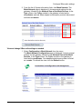
Configuration with a ConnectPort X gateway ................................................ 61
Access the gateway’s web interface........................................................ 61
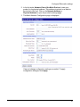
Discover the device and view the network .............................................. 62
View and change XBee radio settings as needed ................................... 63
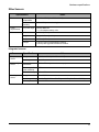
Chapter 13 Hardware specifications .................................................... 67
XBee Adapters .............................................................................................. 67
XStick ZNet 2.5.............................................................................................. 70
XBee Wall Router .......................................................................................... 71
Integrated sensors ................................................................................... 71
XBee Sensors................................................................................................ 72
Integrated sensors ................................................................................... 72
Chapter 14 Safety statements............................................................... 73
Contents
3
General information
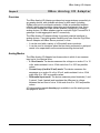
General information
Chapter 1
This section includes information that applies to all XBee™ Adapter,
Router, and Sensor products.
About this guide
This guide describes the features and functions of XBee Adapter, Router,
and Sensor products, including connection and setup information, pinouts,
configuration, data retrieval, and LEDs and buttons.
This section provides general information that applies to all products.
Scope
This guide covers all XBee ZNet 2.5 (Series 2) adapter, router, and sensor
products.
Compatibility Note
Two sets of XBee and XBee-PRO adapters are offered: Series 1 and
Series 2. Though overall performance and product specifications are
largely similar, the two series are built on distinct and non-compatible
technology platforms. Thus, users must standardize on one series or the
other for operability. The same is true for compatibility with the
ConnectPort X gateways. Series 1 XBee adapters are compatible only with
Series 1 gateways, while Series 2 XBee adapters are compatible only with
Series 2 gateways.
Mounting orientation
All XBee Adapters can be mounted in any orientation.
Warranty exception for batteries
Some XBee Adapters and Sensor products ship with alkaline batteries that
must be replaced by the user when discharged and are not covered under
the terms and conditions of the Digi warranty.
Lithium batteries must be replaced by qualified service personnel.
4
General information
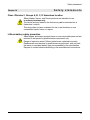
Additional reference material
For additional information about the features and functions of XBee RF
modules in XBee Adapters, see these documents.
XBee Adapters data sheet
http://www.digi.com/pdf/ds_xbeeadapters.pdf
XBee Wall Router data sheet
http://www.digi.com/pdf/ds_xbeewallrouter.pdf
These data sheets provide overviews of XBee Adapter and Wall Router
products, features and benefits, and specifications.
XBee ZNet 2.5 (Series 2) RF Module Product Manual
http://ftp1.digi.com/support/documentation/90000866_A.pdf
Describes the XBee module embedded in your product, including features,
modes of operation, ZigBee and XBee network fundamentals, and
commands for configuring, controlling, and retrieving data from the XBee
module.
ConnectPort X Family User’s Guide (90000832)
http://ftp1.digi.com/support/documentation/90000832_a.pdf
When XBee Adapter, Router, and Sensor products are deployed in Drop-in
Networks, a ConnectPort X gateway serves as a coordinator and
configuration and monitoring interface for your adapter/router/sensor
product. See this guide to learn more about ConnectPort X features and
functions.
Related ConnectPort X documentation
http://www.digi.com/support/supporttype.jsp?tp=3
An extensive list of related documentation for ConnectPort X gateways is
available on digi.com; go to Support > Documentation and select the
appropriate ConnectPort X model.
Digi Python Programming Guide (90000833)
http://ftp1.digi.com/support/documentation/90000833_b.pdf
Python Support Forum on digi.com
http://www.digi.com/support/forum/forum.jspa?forumID=104
Python is a dynamic, object-oriented language for developing software
applications, from simple programs to complex embedded applications.
Python functions can be used to obtain data from integrated sensors on
XBee Adapter, Router, and Sensor products.
The Digi Python Programming Guide introduces the Python programming
language by showing how to create and run a simple Python program. It
reviews Python modules, particularly those modules with Digi-specific
behavior. It describes how to load and run Python programs onto Digi
devices, either through the command-line or web user interfaces, and how
to run several sample Python programs.
5
General information
Questions and technical support
For technical assistance with your product, contact Digi Technical Support
at: 801-765-9885 or 877-912-3444
or make an online support request at:
http://www.digi.com/support/index.jsp
6
XBee RS-232 Adapter
XBee RS-232 Adapter
Chapter 2
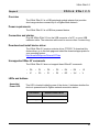
Overview
The XBee RS-232 Adapter provides short range wireless connectivity to
any RS-232 serial device, with available solutions for both mesh (including
ZigBee) and point-to-multipoint networks. Unlike an embedded wireless
module, which requires design integration and development time, these
off-the-shelf adapters provides instant wireless connectivity to existing
RS-232 serial devices. All XBee adapters can be used with Digi's
ConnectPort X gateways for data aggregation and IP connectivity.
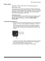
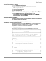
Power options
Depending on adapter model, there are several powering options.
Alkaline battery model
This product can be powered by a 9-30VDC external power supply (see
"Power requirements" on page 68) or by batteries. Use 3x1.5V “N” alkaline
battery cells. To install batteries, insert a screwdriver in the slots in the side
of the adapter case and twist to snap off the cover. Insert the batteries
following the polarity diagram on the board.
Lithium battery model
This model can be powered by a 3-6VDC external power supply or by 2/3
AA 3.6V lithium batteries and a 1/2 AA boost capacitor. Replacement
batteries available for purchase; contact Digi at 952-912-3444 or
877-912-3444.
Connection and power-on
1. Connect the desired device to the RS-232 port of the adapter.
2. Connect the power supply to the adapter or insert batteries.
7
XBee RS-232 Adapter
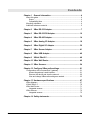
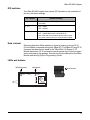
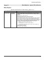
Pinouts
The RS-232 connector is an industry-standard DB9 male connector with a
DTE configuration, similar to a PC serial port. Pinouts for the connector
are:
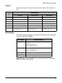
Pin
Function
Data direction
1
CD
Input
2
RXD
Input
3
TXD
Output
4
DTR
Output
5
GND
6
DSR
Input
7
RTS
Output
8
CTS
Input
9
+12VDC switched power out
Output
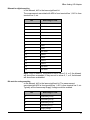
Data retrieval
Retrieving data from XBee adapters is done by issuing a remote AT IS
(Force Sample) command through the XBee API. The XBee API and AT IS
command are described in detail in the XBee ZNet 2.5 (Series 2) RF
Module data sheet. AT IS commands can be issued via a Python program
that is executed on the gateway. See also the Product Manual for the XBee
Module and the Digi Python Programming Guide.
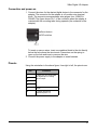
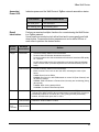
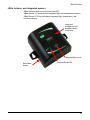
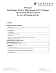
LEDs and buttons
blinking green
Assc
solid green
Ident
Power
8
XBee RS-232 Adapter
Power LED:
Assc LED:
Indicates that power is on. Illuminated only when adapter is connected to
external power only, not when powered by batteries. Not available in
lithium-battery models.
Indicates the adapter’s ZigBee network association status:
LED status
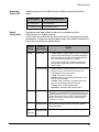
Reset button:
Ident button:
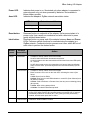
Button
press
Single
Network association
On, solid green
Not associated
On, blinking green
Successfully joined
Recessed button on underside of the adapter. Performs equivalent of a
power-cycle. Use a small non-conducive tool with a blunt end to press
gently and hold down button.
Recessed button on power end of the adapter between Assc and Power
LEDs. Performs multiple functions for commissioning the adapter in a
ZigBee network. Consecutive button presses must occur within 800ms
second of each other to perform the desired action.
Network
association
Action
Associated
•
•
If adapter is asleep, wakes unit for 30 seconds.
Sends a Node Identification broadcast transmission.
All devices that receive this transmission will blink their Associate LED rapidly
for 1 second.
All API devices that receive this transmission will send a Node Identification
frame out their UART (universal asynchronous receiver/transmitter) (API ID
0x95).
Unassociated
•
•
If adapter is asleep, wakes unit for 30 seconds.
Blinks a numeric error code on the Assc LED, indicating the cause of join
failure.
1 blink: Scan found no PANs.
2 blinks: Scan found no valid PANs based on current SC (Scan Channel) and
ID (PAN ID) settings.
3 blinks: Valid Coordinator or Routers found, but they are not allowing joining
(NJ expired).
7 blinks: Node Joining attempt failed.
10 blinks: Coordinator Start attempt failed.
Two
Associated
Temporarily enables joining on the adapter and the entire ZigBee network for 1
minute (if the XBee module’s NJ command setting is less than 255). If joining is
permanently enabled on a module (NJ = 255), joining remains permanently
enabled, and this button press has no effect.
Four
Associated/
Unassociated
Adapter leaves PAN, if associated, and issues a factory reset to restore default
parameters. Default PAN ID is 0x234.
9
XBee RS-232 PH Adapter
XBee RS-232 PH Adapter
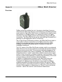
Overview
The XBee RS-232 PH Adapter provides short range wireless connectivity
to any RS-232 serial device, with available solutions for both mesh
(including ZigBee) and point-to-multipoint networks. Unlike an embedded
wireless module, which requires design integration and development time,
these off-the-shelf adapters provides instant wireless connectivity to
existing RS-232 serial devices. All XBee adapters can be used with Digi's
ConnectPort X gateways for data aggregation and IP connectivity
Using a powering mode known as power harvesting (PH), this adapter is
powered by the connected host device through its RS-232 serial port.
Power requirements
This product requires a fully functional serial port conforming to the
RS-232C standard for optimal operation. It requires a sleep/wake duty
cycle as part of its normal operation. An internal battery provides power
when the adapter is operating, and recharges from the serial port when in
sleep mode. The sleep/wake duty cycle requirements vary based on the
current output of serial port
Serial ports that provide hard power of 5 to 14VDC on one or more pins
allow the device to operate continually without a sleep/wake cycle.
WARNING: Do not use this adapter with serial ports with more than 14VDC
output as they may cause the adapter to malfunction.
Connection and power-on
Connect the adapter to the RS-232 port of the host device.
The adapter’s power comes from the host’s serial port.
10
XBee RS-232 PH Adapter
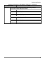
Pinouts
The RS232 connector is an industry-standard DB9 male connector with a
DTE configuration, similar to a PC serial port. Pinouts for the connector
are:
Pin
Function
Data direction
1
CD
Input
Also used for parasitic power input from host.
2
RXD
Input
Also used for parasitic power input from host.
3
TXD
Output
4
DTR
Output
5
GND
6
DSR
Input
Also used for parasitic power input from host.
7
RTS
Output
8
CTS
Input
Also used for parasitic power input from host.
9
RI
Input
Also used for parasitic power input from host.
11
XBee RS-232 PH Adapter
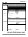
Configuration
There are four key attributes of the Serial PH adapter’s firmware that allow
it to have a net charge on its batteries:
• Sleep Mode (SM)
• Idle Time (ST)
• Sleep Period (SP)
• Sleep Number (SN)
Sleep mode, determines what sleeping behavior the adapter has. By
default the adapter has cyclical sleep enabled. With cyclical sleep enabled,
if the adapter is idle (No RS-232 traffic, no transmit/receive) for the given
amount of Idle Time, it then performs Sleep Number amount of sleeping
cycles, each for the duration of the value of Sleep Period.
The default sleep mode settings are:
• SM = 4 (Cyclical sleep enabled)
• ST = 0x3E8 (Idle time of 1 second)
• SP = 0x40 (Each sleep period’s duration is 640 ms)
• SN = 1 (Perform 1 sleep period when sleeping)
For this configuration, the adapter would sleep for a total of 640 ms when
performing a sleep period, after it was idle for 1 second. During an RF
receive/transmit, the device is in an active state for a significant amount of
time, regardless of the Idle Time setting. If continuous requests/queries are
made to the device, it will stay in an active state, which can lead to a net
discharge of the battery, and eventually the adapter will become
unresponsive.
Adjusting the default settings is not recommended. Doing so can lead to
unit that will not power on. The fix is to remove the module from the adapter
and plug it into the serial line. Then, you can adjust these parameters
through X-CTU software. This software is available on the Software and
Documentation CD that accompanies Drop-in Networking kits and
ConnectPort X gateways.
The battery can take up to 24 hours to fully charge, and if the unit is run in
the worst-case scenario, no sleep mode enabled and continuously queried,
the battery has only a charge for around 40 minutes. After that, the unit will
become unresponsive. In addition, if the unit isn’t immediately put into a
sleep mode after the battery first becomes unable to power the adapter, the
battery will further deplete, and you will have to perform the fix mentioned
above to recover the device.
Data retrieval
Retrieving data from XBee adapters is done by issuing a remote AT IS
(Force Sample) command through the XBee API. The XBee API and AT IS
command are described in detail in the XBee ZNet 2.5 (Series 2) RF
Module data sheet. AT IS commands can be issued via a Python program
that is executed on the gateway. See also the Product Manual for the XBee
Module and the Digi Python Programming Guide.
12
XBee RS-232 PH Adapter
LEDs and buttons
Assoc
Assoc LED:
Ident
Indicates the adapter’s ZigBee network association status:
LED status
Reset button:
Ident button:
Button
press
Single
Reset
Network association
On, solid green
Not associated
On, blinking green
Successfully joined
Performs equivalent of a power-cycle. Use a small non-conducive tool
with a blunt end to press gently and hold down button.
Performs multiple functions for commissioning the adapter in a ZigBee
network. Consecutive button presses must occur within 800 ms of each
other to perform the desired action.
Network
association
Action
Associated
•
•
If adapter is asleep, wakes unit for 30 seconds.
Sends a Node Identification broadcast transmission.
All devices that receive this transmission will blink their Associate LED rapidly
for 1 second.
All API devices that receive this transmission will send a Node Identification
frame out their UART (universal asynchronous receiver/transmitter) (API ID
0x95).
Unassociated
•
•
If adapter is asleep, wakes unit for 30 seconds.
Blinks a numeric error code on the Assc LED, indicating the cause of join
failure.
1 blink: Scan found no PANs.
2 blinks: Scan found no valid PANs based on current SC (Scan Channel) and
ID (PAN ID) settings.
3 blinks: Valid Coordinator or Routers found, but they are not allowing joining
(NJ expired).
7 blinks: Node Joining attempt failed.
10 blinks: Coordinator Start attempt failed.
Two
Associated
Temporarily enables joining on the adapter and the entire ZigBee network for 1
minute (if the XBee module’s NJ command setting is less than 255). If joining is
permanently enabled on a module (NJ = 255), joining remains permanently
enabled, and this button press has no effect.
Four
Associated/
Unassociated
Adapter leaves PAN, if associated, and issues a factory reset to restore default
parameters. Default PAN ID is 0x234.
13
XBee RS-485 Adapter
XBee RS-485 Adapter
Chapter 4
Overview
The XBee RS-485 PH Adapter provides short range wireless connectivity
to any RS-485 serial device, with available solutions for both mesh
(including ZigBee) and point-to-multipoint networks. Unlike an embedded
wireless module, which requires design integration and development time,
these off-the-shelf adapters provides instant wireless connectivity to
existing RS-485 serial devices. All XBee adapters can be used with Digi's
ConnectPort X gateways for data aggregation and IP connectivity
Power options
Depending on adapter model, there are several powering options.
Alkaline battery model
This product can be powered by a 9-30VDC external power supply (see
"Power requirements" on page 68) or by batteries. Use 3x1.5V “N” alkaline
battery cells. To install batteries, insert a screwdriver in the slots in the side
of the adapter case and twist to snap off the cover. Insert the batteries
following the polarity diagram on the board.
Lithium battery model
This model can be powered by a 3-6VDC external power supply or by 2/3
AA 3.6V lithium batteries and a 1/2 AA boost capacitor. Replacement
batteries available for purchase; contact Digi at 952-912-3444 or
877-912-3444.
Connection and power-on
1. Connect the desired device to the RS-485 port of the adapter.
2. Connect the power supply to the adapter or insert batteries.
14
XBee RS-485 Adapter
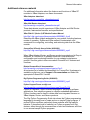
Pinouts
The connector for the adapter is a 6-position wire terminal block. The figure
shows Pin 1 of the connector when the adapter is oriented with the
mounting tabs, facing upwards (the underside of the adapter).
The adapter is switch-selectable between RS-422 half duplex, RS-422 full
duplex, and RS-485 modes (see DIP switches, below). The function for
several pins varies between RS-422 and RS-485 modes.
Using the orientation in the above figure, from right to left, the pinouts are:
Pin
Function in
RS-422 mode
Function in
RS-485 mode
1
TxD+ (RS422)
TxD+ and RxD+ (RS485)
2
TxD- (RS422)
TxD- and RxD- (RS485)
3
RxD+ (RS422)
Not used.
4
RxD- (RS422)
Not used.
5
Ground
Ground
6
+12VDC 50mA max
switched power out
+12VDC 50mA max
switched power out
The connector accommodates wire gauges from 16AWG to 30AWG.
To insert or remove wires, insert a screwdriver blade in the slot directly
below the hole where the wire inserts. Press down on the spring to open up
the hole and insert or remove the wire.
15
XBee RS-485 Adapter
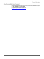
DIP switches
The XBee RS-485 Adapter has several DIP switches on the underside of
the unit, with these settings:
DIP Switch
Switch settings
1
Not used. It is covered up by the case and not
accessible.
2, 3, 4
ON = RS485
OFF = RS422
5, 6
ON = RS485 Bias and line termination on.
OFF = RS485 Bias and line termination off.
Note: Bias and line termination feature can be used
only when powering from the external power supply.
Data retrieval
Retrieving data from XBee adapters is done by issuing a remote AT IS
(Force Sample) command through the XBee API. The XBee API and AT IS
command are described in detail in the XBee ZNet 2.5 (Series 2) RF
Module data sheet. AT IS commands can be issued via a Python program
that is executed on the gateway. See also the Product Manual for the XBee
Module and the Digi Python Programming Guide.
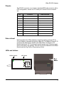
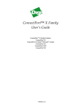
LEDs and buttons
blinking green
Assc
solid green
Ident
Reset button
Power
16
XBee RS-485 Adapter
Power LED:
Assc LED:
Indicates that power is on. Illuminated only when adapter is connected to
external power only, not when powered by batteries. Not available in
lithium-battery models.
Indicates the adapter’s ZigBee network association status:
LED status
Reset button:
Ident button:
Button
press
Single
Network association
On, solid green
Not associated
On, blinking green
Successfully joined
Recessed button on underside of the adapter. Performs equivalent of a
power-cycle. Use a small non-conducive tool with a blunt end to press
gently and hold down button.
Recessed button on power end of the adapter between Assc and Power
LEDs. Performs multiple functions for commissioning the adapter in a
ZigBee network. Consecutive button presses must occur within 800 ms of
each other to perform the desired action.
Network
association
Action
Associated
•
•
If adapter is asleep, wakes unit for 30 seconds.
Sends a Node Identification broadcast transmission.
All devices that receive this transmission will blink their Associate LED rapidly
for 1 second.
All API devices that receive this transmission will send a Node Identification
frame out their UART (universal asynchronous receiver/transmitter) (API ID
0x95).
Unassociated
•
•
If adapter is asleep, wakes unit for 30 seconds.
Blinks a numeric error code on the Assc LED, indicating the cause of join
failure.
1 blink: Scan found no PANs.
2 blinks: Scan found no valid PANs based on current SC (Scan Channel) and
ID (PAN ID) settings.
3 blinks: Valid Coordinator or Routers found, but they are not allowing joining
(NJ expired).
7 blinks: Node Joining attempt failed.
10 blinks: Coordinator Start attempt failed.
Two
Associated
Used only when network joining is permanently enabled (by the XBee Module’s
NJ setting being set to anything other than OFF; in the gateway, this setting is
known as Allows Join Time=255). Temporarily allows joining on the adapter and
the entire ZigBee network for 1 minute.
Four
Associated/
Unassociated
Adapter leaves PAN, if associated, and issues a factory reset to restore default
parameters. Default PAN ID is 0x234.
17
XBee Analog I/O Adapter
Chapter 5
XBee Analog I/O Adapter
Overview
The XBee Analog I/O Adapter provides short range wireless connectivity to
any analog device, with available solutions for both mesh (including
ZigBee) and point-to-multipoint networks. Unlike an embedded wireless
module, which requires design integration and development time, these
off-the-shelf adapters provides instant wireless connectivity to existing
analog devices. All XBee adapters can be used with Digi's ConnectPort X
gateways for data aggregation and IP connectivity.
The XBee Analog I/O adapter allows for several potential interfaces to
analog devices. It provides greater flexibility and uses than the Digi XBee
Sensor Adapter and XBee Sensor products, in that:
• It can be used with a variety of off-the-shelf sensor products.
• It can be used in situations when the item being measured or analyzed
needs to be separated from the sensor/measuring device itself.
Analog Modes
The XBee Analog I/O Adapter has three modes in which it can measure
input on its four terminal lines.
• 0-10 volt mode: The device measures the voltage on a scale of 1 to 10
volts, and translates it into a 10-bit scale from 0 to 1023 as possible
values.
• Current Loop (4 mA to 20 mA) mode: The device measures the
amperage on a scale of 4 mA to 20 mA, and translates it into a 10-bit
scale from 0 to 1023 as possible values.
• Differential input mode: The device measures paired terminals (1 and
2 paired, 3 and 4 paired) and translates the difference in voltage
between the two lines to into a 10-bit scale from 0 to 1023 as possible
values.
A Python module named xbeeain.py is available to set the analog mode;
see pages 24 and 25.
18
XBee Analog I/O Adapter
Power options
Depending on adapter model, there are several powering options.
Alkaline battery model
This product can be powered by a 9-30VDC external power supply (see
"Power requirements" on page 68) or by batteries. Use 3x1.5V “N” alkaline
battery cells. To install batteries, insert a screwdriver in the slots in the side
of the adapter case and twist to snap off the cover. Insert the batteries
following the polarity diagram on the board.
Lithium battery model
This model can be powered by a 3-6VDC external power supply or by 2/3
AA 3.6V lithium batteries and a 1/2 AA boost capacitor. Replacement
batteries available for purchase; contact Digi at 952-912-3444 or
877-912-3444.
Connection and power-on
1. Connect the wires for the desired analog device to the connector for the
adapter. The connector accommodates wire gauges from 16AWG to
30AWG. The connector for the adapter is a 6-position wire terminal
block. The figure shows Pin 1 of the connector when the adapter is
oriented with the mounting tabs, facing upwards (the underside of the
adapter).
To insert or remove wires, insert a screwdriver blade in the slot directly
below the hole where the wire inserts. Press down on the spring to
open up the hole and insert or remove the wire.
2. Connect the power supply to the adapter or insert batteries.
19
XBee Analog I/O Adapter
Pinouts
Using the orientation in the previous figure, from right to left, the pinouts
are:
Analog Mode
Pin
Ten Volt
Current Loop
Differential
1
0-10 Volt
4-20 mA
Terminal Pair 1 positive
2
0-10 Volt
4-20 mA
Terminal Pair 1 negative
3
0-10 Volt
4-20 mA
Terminal Pair 2 positive
4
0-10 Volt
4-20 mA
Terminal Pair 2 negative
5
Ground
Ground
Ground
+12VDC 50mA max
switched power out
+12VDC 50mA max
switched power out
+12VDC 50mA max
switched power out
DIP switches
The XBee Analog I/O Adapter has several DIP switches on the underside
of the unit, with these settings:
DIP Switch
Switch settings
1
Enables and disables direct battery pack voltage
output.
On=battery power out
Off=no battery power out
2
Enables and disables +12V power out.
On=+12V power out
Off=no +12V power out
3
Not used
4
Not used
Note: Switches 1 and 2 should not be on at the same time as increased
parasitic battery drain will result.
20
XBee Analog I/O Adapter
Configuring inputs and outputs
Input selection
Six control lines from the XBee module are used to place the four external
terminals into the desired input mode.
The power-on default is 0-10VDC on all four terminals.
Set the analog mode
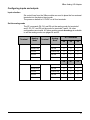
The AT commands D8, D4, and D6 set the analog mode for terminals 1
and 2. P0, D7, and P2 set the mode for terminals 3 and 4. All other
configurations are invalid. A Python module named xbeeain.py is available
to set the analog mode; see pages 24 and 25.
Terminal
Terminal 1
Terminal 3
Analog
Mode
Terminal
Analog
Mode
AT Commands
D8
D4
D6
Current Loop
0
0
0
Current Loop
Ten Volt
0
0
1
Ten Volt
Current Loop
0
1
0
Ten Volt
Ten Volt
0
1
1
Differential
Differential
1
0
0
P0
D7
P2
Current Loop
0
0
0
Current Loop
Ten Volt
0
0
1
Ten Volt
Current Loop
0
1
0
Ten Volt
Ten Volt
0
1
1
Differential
Differential
1
0
0
Current Loop
Current Loop
Terminal 2
Terminal 4
21
XBee Analog I/O Adapter
Enable a terminal line for measurement
To enable a terminal line for measurement, the following analog I/O lines
have to be set to value 2:
• D0
• D1
• D2
• D3
D0, D1, D2, and D3 represent terminal lines 1, 2, 3, and 4 respectively. In
the case of a terminal pair in differential mode, only the first terminal of the
terminal pair should be enabled. To disable a terminal line, set the
respective analog I/O line to value 0.
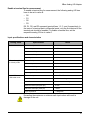
Input specifications and characteristics
Analog mode
0-10 volt mode
Current Loop (4 mA
to 20 mA) mode
+/- 2 VDC
differential mode
Specification
Value
Full-scale input
10.25 VDC
Minimum input
0 VDC
Maximum safe input
11VDC
Minimum safe input
-.5VDC
Input impedance
28200 ohms
Full-scale input
23.5mA
Minimum input
0mA
Maximum safe input
40mA
Minimum safe input
-.5VDC
Input impedance
51.1 ohms
Full-scale input
+2.4 VDC differential
0V differential
Half-scale reading
-2V differential
Minimum-scale reading
Maximum safe input (each pin)
11VDC
Minimum safe input (each pin)
-.5VDC
Input impedance
~1 Megaohm
Exceeding the maximum or minimum safe input values will result in
damage to the unit.
22
XBee Analog I/O Adapter
Power output specifications
External terminal 6 is a power-out pin. It can be set to either battery pack
voltage out or +12VDC at 50mA out via DIP switches 1 and 2.
External terminal 5 is a system ground pin. This ground pin should be used
for all external ground connections for both power and input connections.
DIP switch 1 enables battery pack voltage minus .5VDC to terminal 6,
resulting in 4VDC out with new alkaline batteries, or 3.1VDC with new
lithium battery. DIP switch 2 enables +12VDC to terminal 6. Only one
switch should be on at a time. No damage will happen if both are set to on,
but the output will default to the +12VDC output and increased parasitic
battery drain will result.
The battery pack voltage is on terminal 6 all the time, and is not gated with
the sleep of the module when DIP switch 2 is on. Any current draw from
terminal 6 will result in reduced battery life.
When DIP switch 2 is on, the +12VDC at 50mA max is provided at terminal
6. This power is gated by both the sleep of the module and AT command
P3. For this power setting to be on, the XBee module needs to be awake
and AT command P3 set to a high level.
23
XBee Analog I/O Adapter
Python modules for configuring inputs and outputs
Digi provides a library of Python modules for configuring inputs and outputs
on the adapter and retrieving data from the adapter. These modules are
available for downloading from www.digi.com/din/docs, in a file named
XBee Adapter Libraries. By uploading these Python modules to the
gateway that serves as a coordinator for the adapter, you can use them in
your own programs.
Python module descriptions
The Python modules in the XBee Adapter Libraries that are relevant to
programming the XBee Analog I/O Adapter are:
Module
Description
xbeeprodid.py
Contains calls to determine the type of adapter; (Analog,
Digital, Sensor, RS-232, etc.)
xbeedevice.py
Implements a base class of any XBee device on the ZigBee
network.
xbeeain.py
Configures analog mode, issues AT commands to retrieve
data from the adapter, including raw analog sample data
and sensor data scaled appropriately for operating mode,
and toggles power on/off on terminal 6. Functions and
arguments are shown on page 25.
This module derives an AIO (analog input/output) class from
the base class of any XBee device on the ZigBee network.
That is, module xbeeain.py uses xbeedevice.py internally.
sensor_io.py
Decodes the output of the AT IS command.
Upload Python modules to gateway
1. Go to www.digi.com/din/docs.
2. In the list of downloadable files, select and download file
XBee Adapter Libraries.
3. Unzip the downloaded file.
4. Read the readme file.
5. Open the web interface for the gateway, go to Applications > Python.
6. In the Upload File edit box, enter the file name for the
XBee Adapter Libraries, DigiXBeeDrivers.zip, using the Browse
button as needed, and click Upload.
Use Python modules in programs
To use the Python modules in the XBee Adapter Libraries in programs that
you develop, append this statement:
sys.path.append("WEB/python/DigiXBeeDrivers.zip")
24
XBee Analog I/O Adapter
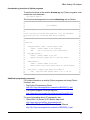
Use xbeeain.py functions in Python programs
To use the functions in the module xbeeain.py, any Python programs must
contain the next statement:
from xbeeain import *
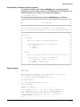
The functions and arguments in module xbeeain.py are as follows.
############################################################################
#
#
#
Class XBeeAIN
#
#
#
############################################################################
#
#
# This class derives from the base XBeeDevice class, and implements
#
# the Analog IO layer of the Digi XBee Analog IO Adapter.
#
#
#
############################################################################
#
#
# Functions:
#
#
#
#
configure(channel, mode) - Define channel usage
#
#
channel - Channel number to be configured.
#
#
mode
- One of (CurrentLoop, TenV, Differential)
#
#
#
#
raw_sample(channel)
#
#
channel - Channel number to be read.
#
#
Returns raw analog sample data for specified channel
#
#
#
#
sample(channel)
#
#
channel - Channel number to be read.
#
#
Returns sensor data scaled appropriately for operating mode
#
#
#
#
power(onoff) - Toggles Power Output on Terminal 6.
#
#
onoff - Specifies Power Output either on (1) or off (0).
#
#
#
############################################################################
Additional programming resources
For further information on writing Python programs and using Python
functions, see:
• Digi Python Programming Guide
http://ftp1.digi.com/support/documentation/90000833_b.pdf
• The Python Support Forum on digi.com
http://www.digi.com/support/forum/forum.jspa?forumID=104
For more information about AT commands, see:
• XBee ZNet 2.5 (Series 2) RF Module data sheet
http://www.digi.com/pdf/ds_xbeemodules.pdf
• XBee ZNet 2.5 (Series 2) RF Module Product Manual
http://ftp1.digi.com/support/documentation/90000866_A.pdf
25
XBee Analog I/O Adapter
Data retrieval
To retrieve measurement data from the XBee Analog I/O Adapter, use
these Python modules, provided in the XBee Adapter Libraries:
• xbeeain.py: Issues the AT IS command to retrieve the data.
• sensor_io.py: Decodes the output of the AT IS command.
Byte structure returned by IS command
The AT IS (Force Sample) command is used to force a read of all enabled
analog I/O lines. The command returns a byte structure that identifies
which lines are enabled for digital or analog sampling, and the current
measurement.
Byte size
Purpose
1
The number of samples in this message.
2
Bitmask of which digital I/O lines are enabled for this sample.
1
Bitmask of which analog I/O lines are enabled for this sample.
2
Digital sample, only present if any digital I/O lines are
enabled.
2*N
Analog sample, N is the number of analog I/O lines enabled.
Number of samples
The number of samples in this reading. Should always be 0x01.
26
XBee Analog I/O Adapter
Bitmask for digital sampling
In this bitmask, bit 0 is the lease significant bit.
The measurement associated with AD0 is from terminal line 1, AD1 is from
terminal line 2, etc.
Bit
Matching I/O line
0
AD0/DIO0
1
AD1/DIO1
2
AD2/DIO2
3
AD3/DIO3
4
DIO4
5
Assoc/DIO5
6
DIO6
7
DIO7
8
DIO8
9
Not Used
10
DIO10
11
DIO11
12
DIO12
13
DIO13
14
Not Used
15
Not Used
Note: If any of these AT commands is set to values 3, 4, or 5, the bitmask
will show them as enabled. If they are set to values 0, 1, or 2, the bitmask
will show them as disabled.
Bit mask for analog sampling
In this bitmask, bit 0 is the lease significant bit. The measurement
associated with AD0 is from terminal line 1, AD1 is from terminal line 2, etc.
Typically all the lines except Supply Voltage would be enabled.
Bit
Matching I/O line
0
AD0/DIO0 (pin 20)
1
AD1/DIO1 (pin 19)
2
AD2/DIO2 (pin 18)
3
D3/DIO3 (pin 17)
7
Supply Voltage
27
XBee Analog I/O Adapter
Digital sample
This field should be ignored.
Analog sample
Contains the measured results from the analog-enabled digital I/O lines.
This example is for a 10-bit sample.
Each measurement is 2 bytes long, and ranges between 0-1023 for value
(10 bit resolution). The lowest lines are always first, so if digital I/O 0 and 2
were enabled, the first 2 bytes would represent digital I/O 0’s measurement
and the second two bytes would represent digital I/O 2’s measurement.
LEDs and buttons
blinking green
Assc
solid green
Ident
Reset button
Power
28
XBee Analog I/O Adapter
Power LED:
Assc LED:
Indicates that power is on. Illuminated only when adapter is connected to
external power only, not when powered by batteries. Not available in
lithium-battery models.
Indicates the adapter’s ZigBee network association status:
LED status
Reset button:
Ident button:
Button
press
Single
Network association
On, solid green
Not associated
On, blinking green
Successfully joined
Recessed button on underside of the adapter. Performs equivalent of a
power-cycle. Use a small non-conducive tool with a blunt end to press
gently and hold down button.
Recessed button on power end of the adapter between Assc and Power
LEDs. Performs multiple functions for commissioning the adapter in a
ZigBee network. Consecutive button presses must occur within 800 ms of
each other to perform the desired action.
Network
association
Action
Associated
•
•
If adapter is asleep, wakes unit for 30 seconds.
Sends a Node Identification broadcast transmission.
All devices that receive this transmission will blink their Associate LED rapidly
for 1 second.
All API devices that receive this transmission will send a Node Identification
frame out their UART (universal asynchronous receiver/transmitter) (API ID
0x95).
Unassociated
•
•
If adapter is asleep, wakes unit for 30 seconds.
Blinks a numeric error code on the Assc LED, indicating the cause of join
failure.
1 blink: Scan found no PANs.
2 blinks: Scan found no valid PANs based on current SC (Scan Channel) and
ID (PAN ID) settings.
3 blinks: Valid Coordinator or Routers found, but they are not allowing joining
(NJ expired).
7 blinks: Node Joining attempt failed.
10 blinks: Coordinator Start attempt failed.
Two
Associated
Temporarily enables joining on the adapter and the entire ZigBee network for 1
minute (if the XBee module’s NJ command setting is less than 255). If joining is
permanently enabled on a module (NJ = 255), joining remains permanently
enabled, and this button press has no effect.
Four
Associated/
Unassociated
Adapter leaves PAN, if associated, and issues a factory reset to restore default
parameters. Default PAN ID is 0x234.
29
XBee Digital I/O Adapter
XBee Digital I/O Adapter
Chapter 6
Overview
The XBee Digital I/O Adapter provides short range wireless connectivity to
any digital device, as well as an interface to logic-level inputs and sinking
driver output. Solutions are available for both mesh (including ZigBee) and
point-to-multipoint networks. Unlike an embedded wireless module, which
requires design integration and development time, these off-the-shelf
adapters provides instant wireless connectivity to existing digital devices.
All XBee adapters can be used with Digi's ConnectPort X gateways for
data aggregation and IP connectivity.
Power options
Depending on adapter model, there are several powering options.
Alkaline battery model
This product can be powered by a 9-30VDC external power supply (see
"Power requirements" on page 68) or by batteries. Use 3x1.5V “N” alkaline
battery cells. To install batteries, insert a screwdriver in the slots in the side
of the adapter case and twist to snap off the cover. Insert the batteries
following the polarity diagram on the board.
Lithium battery model
This model can be powered by a 3-6VDC external power supply or by 2/3
AA 3.6V lithium batteries and a 1/2 AA boost capacitor. Replacement
batteries available for purchase; contact Digi at 952-912-3444 or
877-912-3444.
30
XBee Digital I/O Adapter
Connection and power-on
1. Connect the wires for the desired digital device to the connector for the
adapter. The connector for the adapter is a 6-position wire terminal
block. The connector accommodates wire gauges from 16AWG to
30AWG. The figure shows Pin 1 of the connector when the adapter is
oriented with the mounting tabs, facing upwards (the underside of the
adapter).
To insert or remove wires, insert a screwdriver blade in the slot directly
below the hole where the wire inserts. Press down on the spring to
open up the hole and insert or remove the wire.
2. Connect the power supply to the adapter or insert batteries.
Pinouts
Using the orientation in the above figure, from right to left, the pinouts are:
Pin
1
2
Function
These pins are configurable
as digital input or sinking
driver output.
3
4
5
GND
6
+12VDC 50mA max
switched power out
31
XBee Digital I/O Adapter
DIP switches
The XBee Digital I/O Adapter has several DIP switches on the underside of
the unit, with these settings:
DIP Switch
Switch settings
1
Enables and disables direct battery pack voltage
output.
On=battery power out
Off=no battery power out
2
Enables and disables +12V power out.
On=+12V power out
Off=no +12V power out
3
Turns on 10K pullup on terminal 1 to 3VDC.
4
Turns on 10K pullup on terminal 2 to 3VDC.
Note:
• Switches 1 and 2 should not be on at the same time as increased
parasitic battery drain will result.
• Pullup use is not recommended when running from battery power,
owing to the constant drain on the batteries.
32
XBee Digital I/O Adapter
Configuring inputs and outputs
As shown in the pinouts table, the XBee Digital I/O Adapter product has
four external terminals that can be set as either a digital input or a sinking
driver output.
The XBee module controls the sinking drivers on pins 11, 16, 12, 4 for
terminals 1, 2, 3, 4 respectively.
The AT commands to the XBee module for the output function are D4, D6,
D7, P2 for terminals 1, 2, 3, 4 respectively.
Outputs are activated (that is, the sinking function is turned on) by setting
high the corresponding XBee pin for the output that is desired. To set a
terminal high, set the corresponding AT command to value 5. To set a
terminal low, set the corresponding AT command to value 4. For example,
setting terminal 1 to high would call the AT command D4 and set it to value
5.
Since the input and output functions overlap, the input function is always
active and when the input function is desired, the output control pin for the
matching output must be set low (turns off the sinking function). This
feature can allow the inputs to monitor the output sinking operation if
desired.
Input/output specifications and characteristics
Digital mode
Digital Input
Digital Output
Specification
Value
Input type
Non-inverting Schmidt trigger gate
Positive-going switching threshold
~1.6 VDC
Negative-going switching threshold
~1.0 VDC
Maximum safe input
+30VDC
Minimum safe input
-.5VDC
Input impedance
~1.5 Megaohms
Default level when no input applied
Low
Output type
Open collector sinking driver
Maximum sink current
1.8ADC
Maximum off voltage
+30VDC
Minimum safe input
-.5VDC
Resistor pullups
10K ohms pulled up to 3VDC; switchselectable
Exceeding the maximum or minimum safe input values will result in
damage to the unit.
33
XBee Digital I/O Adapter
Power output specifications
External terminal 6 is a power-out pin. It can be set to either battery pack
voltage out or +12VDC at 50mA out via DIP switches 1 and 2.
External terminal 5 is a system ground pin. This ground pin should be used
for all external ground connections for both power and input connections.
DIP switch 1 enables battery pack voltage minus .5VDC to terminal 6,
resulting in 4VDC out with new alkaline batteries, or 3.1VDC with new
lithium battery. DIP switch 2 enables +12VDC to terminal 6. Only one
switch should be on at a time. No damage will happen if both are set to on,
but the output will default to the +12VDC output and increased parasitic
battery drain will result.
The battery pack voltage is on terminal 6 all the time and not gated with the
sleep of the module when DIP switch 2 is on. Any current draw from
terminal 6 will result in reduced battery life. This mode is primarily intended
with switch closure applications with the XBee Digital I/O Adapter with the
external switch in the customer equipment in the normally open position, so
no battery current results until the activating event happens.
When DIP switch 2 is on, the +12VDC at 50mA max is provided at terminal
6. This power is gated by both the sleep of the module and AT command
P3. For this power setting to be on, the XBee module needs to be awake
and AT command P3 set to a high level.
34
XBee Digital I/O Adapter
Python modules for configuring inputs and outputs
Digi provides a library of Python modules for configuring inputs and outputs
on the adapter and retrieving data from the adapter. These modules are
available for downloading from www.digi.com/din/docs, in a file named
XBee Adapter Libraries. By uploading these Python modules to the
gateway that serves as a coordinator for the adapter, you can use them in
your own programs.
The Python modules in the zip file that are relevant to programming the
XBee Digital I/O Adapter are:
Module
Description
xbeeprodid.py
Contains calls to determine the type of adapter; (Analog,
Digital, Sensor, RS-232, etc.)
xbeedevice.py
Implements a base class of any XBee device on the ZigBee
network.
xbeedin.py
Configures inputs and outputs, issues AT commands to
retrieve data from the adapter, and toggles power on/off on
terminal 6. Functions and arguments are shown page 36.
Derives an DIO (digital input/output) class from the base
class of any Digi Xbee device on the mesh network. That is,
module xbeedin.py uses xbeedevice.py internally.
sensor_io.py
Decodes the output of the AT IS command.
Upload Python modules to gateway
1. Go to www.digi.com/din/docs.
2. In the list of downloadable files, select and download file
XBee Adapter Libraries.
3. Unzip the downloaded file.
4. Read the readme file.
5. Open the web interface for the gateway, go to Applications > Python.
6. In the Upload File edit box, enter the file name for the
XBee Adapter Libraries, DigiXBeeDrivers.zip, using the Browse
button as needed, and click Upload.
Use Python modules in programs
To use the Python modules in the XBee Adapter Libraries in programs that
you develop, append this statement:
sys.path.append("WEB/python/DigiXBeeDrivers.zip")
35
XBee Digital I/O Adapter
Use xbeedin.py functions in Python programs
To use the functions in the module xbeedin.py for programming inputs and
outputs, any Python programs you create must contain this statement:
from xbeedin import *
The functions and arguments in module xbeedin.py are as follows.
############################################################################
#
#
#
Class XBeeDIN
#
#
#
############################################################################
#
#
# This class derives from the base XBeeDevice class, and implements
#
# the Digital IO layer of the Digi XBee Digital IO Adapter.
#
#
#
############################################################################
#
#
# Functions:
#
#
#
#
configure(channel, mode, highlow) - Define channel usage
#
#
channel - Channel number to be configured.
#
#
mode
- One of (Input, Output)
#
#
highlow - If in Output mode, this specifies whether the signal
#
#
should be driven high (1) or low (0).
#
#
#
#
sample(channel)
#
#
channel - Channel number to be read.
#
#
Returns digital sample data for specified channel
#
#
#
#
power(onoff) - Toggles Power Output on Terminal 6.
#
#
onoff - Specifies Power Output either on (1) or off (0).
#
#
#
############################################################################
Additional programming resources
For further information on writing Python programs and using Python
functions, see:
• Digi Python Programming Guide
http://ftp1.digi.com/support/documentation/90000833_b.pdf
• The Python Support Forum on digi.com
http://www.digi.com/support/forum/forum.jspa?forumID=104
For more information about AT commands, see:
• XBee ZNet 2.5 (Series 2) RF Module data sheet
•
http://www.digi.com/pdf/ds_xbeemodules.pdf
XBee ZNet 2.5 (Series 2) RF Module Product Manual
http://ftp1.digi.com/support/documentation/90000866_A.pdf
36
XBee Digital I/O Adapter
Data retrieval
To retrieve measurement data from the XBee Digital I/O Adapter, use these
Python modules, provided in the XBee Adapter Libraries:
• xbeedin.py: Issues the AT IS command to retrieve the data.
• sensor_io.py: Decodes the output of the AT IS command.
To enable a terminal line for measurement, the following digital I/O lines
have to be set to value 3:
• D8
• D1
• D2
• D3
D8, D1, D2, and D3 represent terminal lines 1, 2, 3, and 4 respectively. To
disable a terminal line, set the respective digital I/O line to value 0.
Following is a description of the data returned by the IS command.
Byte structure returned by IS command
The AT IS (Force Sample) command is used to force a read of all enabled
digital I/O lines. The command returns a byte structure that identifies which
lines are enabled for digital or analog sampling, and the current
measurement.
Byte size
Purpose
1
The number of samples in this message.
2
Bit mask of which digital I/O lines are enabled for this sample.
1
Bit mask of which analog I/O lines are enabled for this sample.
2
Digital sample, present only if any digital I/O lines are enabled.
2*N
Analog sample; N is the number of analog I/O lines enabled.
Number of samples
This represents the number of samples that make up the measurement.
This number is most commonly set to 1.
37
XBee Digital I/O Adapter
Bit mask for digital sampling
In this bitmask, bit 0 is the lease significant bit.
The measurement associated with AD0 is from terminal line 1, AD1 is from
terminal line 2, etc.
Bit
Matching I/O line
0
AD0/DIO0
1
AD1/DIO1
2
AD2/DIO2
3
AD3/DIO3
4
DIO4
5
Assoc/DIO5
6
DIO6
7
DIO7
8
DIO8
9
Not Used
10
DIO10
11
DIO11
12
DIO12
13
DIO13
14
Not Used
15
Not Used
Note: If any of these AT commands is set to values 3, 4, or 5, the bitmask
will show them as enabled. If they are set to values 0, 1, or 2, the bitmask
will show them as disabled.
Bit mask for analog sampling
Should always be 0x00 on the digital adapter.
Digital sample
The ninth LSB (least significant bit) represents terminal line 1. Terminal line
2 is represented by the second LSB. Terminal line 3 is represented by the
third LSB, and terminal Line 4 is represented by the fourth LSB.
38
XBee Digital I/O Adapter
LEDs and buttons
blinking green
Assc
Power LED:
Assc LED:
solid green
Ident
Reset button
Power
Indicates that power is on. Illuminated only when adapter is connected to
external power only, not when powered by batteries. Not available in
lithium-battery models.
Indicates the adapter’s ZigBee network association status:
LED status
Network association
On, solid green
Not associated
On, blinking green
Successfully joined
39
XBee Digital I/O Adapter
Reset button:
Ident button:
Button
press
Single
Recessed button on underside of the adapter. Performs equivalent of a
power-cycle. Use a small non-conducive tool with a blunt end to press
gently and hold down button.
Recessed button on power end of the adapter between Assc and Power
LEDs. Performs multiple functions for commissioning the adapter in a
ZigBee network. Consecutive button presses must occur within 800 ms of
each other to perform the desired action.
Network
association
Action
Associated
•
•
If adapter is asleep, wakes unit for 30 seconds.
Sends a Node Identification broadcast transmission.
All devices that receive this transmission will blink their Associate LED rapidly
for 1 second.
All API devices that receive this transmission will send a Node Identification
frame out their UART (universal asynchronous receiver/transmitter) (API ID
0x95).
Unassociated
•
•
If adapter is asleep, wakes unit for 30 seconds.
Blinks a numeric error code on the Assc LED, indicating the cause of join
failure.
1 blink: Scan found no PANs.
2 blinks: Scan found no valid PANs based on current SC (Scan Channel) and
ID (PAN ID) settings.
3 blinks: Valid Coordinator or Routers found, but they are not allowing joining
(NJ expired).
7 blinks: Node Joining attempt failed.
10 blinks: Coordinator Start attempt failed.
Two
Associated
Temporarily enables joining on the adapter and the entire ZigBee network for 1
minute (if the XBee module’s NJ command setting is less than 255). If joining is
permanently enabled on a module (NJ = 255), joining remains permanently
enabled, and this button press has no effect.
Four
Associated/
Unassociated
Adapter leaves PAN, if associated, and issues a factory reset to restore default
parameters. Default PAN ID is 0x234.
40
XBee Sensor Adapter
XBee Sensor Adapter
Chapter 7
Overview
The XBee Sensor Adapter provides short range wireless connectivity to
Digi Watchport® Sensors, with available solutions for both mesh (including
ZigBee) and point-to-multipoint networks. Unlike an embedded wireless
module, which requires design integration and development time, these
off-the-shelf adapters provides instant wireless connectivity to existing
Watchport Sensors. All XBee adapters can be used with Digi's
ConnectPort X gateways for data aggregation and IP connectivity
Available sensor products
The XBee Sensor Adapter can be used with a variety of Watchport
sensors. For a description and list of supported sensors, go to Digi’s
Drop-in Networking page at www.digi.com/din, navigate to Products, and
click on Sensors.
Power options
Depending on adapter model, there are several powering options.
Alkaline battery model
This product can be powered by a 9-30VDC external power supply (see
"Power requirements" on page 68) or by batteries. Use 3x1.5V “N” alkaline
battery cells. To install batteries, insert a screwdriver in the slots in the side
of the adapter case and twist to snap off the cover. Insert the batteries
following the polarity diagram on the board.
Lithium battery model
This model can be powered by a 3-6VDC external power supply or by 2/3
AA 3.6V lithium batteries and a 1/2 AA boost capacitor. Replacement
batteries available for purchase; contact Digi at 952-912-3444 or
877-912-3444.
Connection and power-on
1. Connect the sensor to the SENSOR port of the adapter.
2. Connect the power supply to the adapter or insert batteries.
41
XBee Sensor Adapter
Pinouts
The XBee Sensor Adapter uses an industry-standard RJ45 10 pin modular
jack with these pinouts:
Pin
Function
1
Not used.
2
Not used.
3
Not used.
4
GND
5
1-wire (sensor) data
6
+5VDC switched power out.
7
GND
8
+5VDC switched power out.
9
General-purpose logic input for moisture sensor.
10
Not used.
42
XBee Sensor Adapter
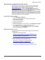
Sensor function configuration and data retrieval
Digi provides a Python module for configuring sensor functions and
retrieving data from XBee Sensor Adapters. This module is named
xbee_sensor.py and is available for downloading from
www.digi.com/din/docs, in a file named XBee Adapter Libraries. By
uploading this Python module to the gateway that serves as a coordinator
for the adapter, you can use it in your own programs. The
XBee Adapter Libraries file includes a readme file and a sample program
showing how xbee_sensor.py is used. xbee_sensor.py issues a remote
AT 1S (Force Sample) command through the XBee API and decodes the
results. See these files for more information.
Upload Python modules to gateway
1. Go to www.digi.com/din/docs.
2. In the list of downloadable files, select and download file
XBee Adapter Libraries.
3. Unzip the downloaded file.
4. Read the readme file.
5. Open the web interface for the gateway, go to Applications > Python.
6. In the Upload File edit box, enter the file name for the
XBee Adapter Libraries, DigiXBeeDrivers.zip, using the Browse
button as needed, and click Upload.
Additional programming resources
For further information on writing Python programs and using Python
functions, see:
• Digi Python Programming Guide
http://ftp1.digi.com/support/documentation/90000833_b.pdf
• The Python Support Forum on digi.com
http://www.digi.com/support/forum/forum.jspa?forumID=104
For more information about AT commands, see:
• XBee ZNet 2.5 (Series 2) RF Module data sheet
http://www.digi.com/pdf/ds_xbeemodules.pdf
• XBee ZNet 2.5 (Series 2) RF Module Product Manual
http://ftp1.digi.com/support/documentation/90000866_A.pdf
43
XBee Sensor Adapter
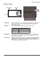
LEDs and buttons
blinking green
Assc
Power LED:
Assc LED:
solid green
Ident
Power
Indicates that power is on. Illuminated only when adapter is connected to
external power only, not when powered by batteries. Not available in
lithium-battery models.
Indicates the adapter’s ZigBee network association status:
LED status
Reset button:
Ident button:
Network association
On, solid green
Not associated
On, blinking green
Successfully joined
Recessed button on underside of the adapter. Performs equivalent of a
power-cycle. Use a small non-conducive tool with a blunt end to press
gently and hold down button.
Recessed button on power end of the adapter between Assc and Power
LEDs. Performs multiple functions for commissioning the adapter in a
ZigBee network. Consecutive button presses must occur within 800 ms of
each other to perform the desired action.
44
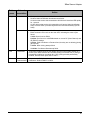
XBee Sensor Adapter
Button
press
Single
Network
association
Action
Associated
•
•
If adapter is asleep, wakes unit for 30 seconds.
Sends a Node Identification broadcast transmission.
All devices that receive this transmission will blink their Associate LED rapidly
for 1 second.
All API devices that receive this transmission will send a Node Identification
frame out their UART (universal asynchronous receiver/transmitter) (API ID
0x95).
Unassociated
•
•
If adapter is asleep, wakes unit for 30 seconds.
Blinks a numeric error code on the Assc LED, indicating the cause of join
failure.
1 blink: Scan found no PANs.
2 blinks: Scan found no valid PANs based on current SC (Scan Channel) and
ID (PAN ID) settings.
3 blinks: Valid Coordinator or Routers found, but they are not allowing joining
(NJ expired).
7 blinks: Node Joining attempt failed.
10 blinks: Coordinator Start attempt failed.
Two
Associated
Temporarily enables joining on the adapter and the entire ZigBee network for 1
minute (if the XBee module’s NJ command setting is less than 255). If joining is
permanently enabled on a module (NJ = 255), joining remains permanently
enabled, and this button press has no effect.
Four
Associated/
Unassociated
Adapter leaves PAN, if associated, and issues a factory reset to restore default
parameters. Default PAN ID is 0x234.
45
XBee USB Adapter
XBee USB Adapter
Chapter 8
Overview
The XBee USB Adapter provides short range wireless connectivity to any
USB device, with available solutions for both mesh (including ZigBee) and
point-to-multipoint networks. Unlike an embedded wireless module, which
requires design integration and development time, these off-the-shelf
adapters provides instant wireless connectivity to existing USB devices. All
XBee adapters can be used with Digi's ConnectPort X gateways for data
aggregation and IP connectivity
Power requirements
The XBee USB Adapter is a bus-powered device.
Download and install device driver
The XBee USB Adapter requires a device driver, FT232R. This device
driver causes adapter device to appear as an additional COM port
available to the PC. Application software can access the adapter in the
same way as it would access a standard COM port.
To download this device driver, go to this web page and select the
download appropriate for your operating system:
http://www.ftdichip.com/Drivers/VCP.htm
Data retrieval
Retrieving data from XBee adapters is done by issuing a remote AT IS
(Force Sample) command through the XBee API. The API and AT IS
command are described in detail in the XBee ZNet 2.5 (Series 2) RF
Module data sheet. These AT IS commands can be issued via a Python
program that is executed on the gateway. See also the Product Manual for
the XBee Module and the Digi Python Programming Guide.
46
XBee USB Adapter
LEDs and buttons
There is one LED and one button on the end of the adapter opposite the
USB connector:
Assoc
Reset
Associate/Power LED;
blinking green=associated
Associate/
Power LED:
Indicates power and the adapter’s ZigBee network association status:
LED status
Reset button:
Reset button
Network association
On, solid green
Powered and not associated.
On, blinking green
Powered and associated.
Performs a reset.
Use a small non-conducive tool with a blunt end to press gently and hold
down button. Consecutive button presses must occur within 800 ms of
each other to perform the desired action.
47
XStick ZNet 2.5
XStick ZNet 2.5
Chapter 9
Overview
The XStick ZNet 2.5 is a USB peripheral module adapter that provides
short-range wireless connectivity to a ZigBee Mesh network.
Power requirements
The XStick ZNet 2.5 is a USB bus-powered device.
Connection and startup
Plug the XStick ZNet 2.5 into the USB connector of a PC, or use a USB
extension cable. The extension cable must be no more than 3 meters long.
Download and install device driver
The XStick ZNet 2.5 requires a device driver, FT232R. To download this
device driver, go to this web page and select the download appropriate for
your operating system:
http://www.ftdichip.com/Drivers/VCP.htm
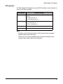
Unsupported XBee AT commands
The XStick ZNet 2.5 does not support these XBee AT commands:
•
D0
•
D1
•
D2
•
D3
•
D4
•
D6
•
IS
•
IC
•
P0
•
P1
•
P2
•
RP
•
%V
•
V
LEDs and buttons
Associate/
Power LED:
This LED is located inside the case of the device. It indicates whether the
device is powered and its ZigBee network association status:
LED status
Network association
Off
Not associated.
On, blinking green
Powered and associated.
48
XBee Wall Router
Chapter 10
XBee Wall Router
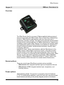
Overview
ZigBee technology enables low-cost, low-power networking of sensors,
controllers and other such devices in self-configuring, self-healing wireless
mesh networks. Digi's XBee Wall Router is a small extender used to create
the backbone of a ZigBee network or to expand the range of a ZigBee
network so that other ZigBee devices can seamlessly communicate with
one another. The XBee Wall Router can be used with Digi's ConnectPort X
gateways for data aggregation and IP connectivity.
Part of Digi's Drop-in Networking solutions, the XBee Wall Router helps to
create and/or fortify the infrastructure of a ZigBee network by simply
plugging into standard wall power sockets around a customer facility,
creating a multi-path self-healing network. Installation is easy and
completely unobtrusive.
The U.S. version of the XBee Wall Router includes a built-in mounting tab,
which allows it to be securely screwed into standard wall sockets using the
existing mounting screw hole. This prevents accidental unplugging of the
repeater and reduces risk of theft or vandalism. The XBee Wall Router is
designed primarily to “patch” areas within a ZigBee network where signal
erosion or loss occurs due to distance limitations or air interference. It also
serves to create multiple pathways, increasing the redundancy of the mesh
communications to ensure maximum network reliability.
In addition to ZigBee network extension, the XBee Wall Router also
includes two integrated environmental sensors. Customers using
ConnectPort X gateways have the ability to retrieve data from ZigBee
enabled temperature and light sensors built inside of the product. XBee
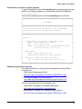
wall routers can be used with ConnectPort X gateways, XBee embedded
modules, XBee adapters or XBee sensors to "drop-in" end-to-end device
networks – without the need for a wired network infrastructure.
49
XBee Wall Router
Connection and startup
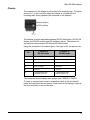
1. Plug the XBee Wall Router into an outlet.
2. To make sure your XBee Wall Router is properly connected to the
ZigBee network, check the Associate/Power LED, as described
above.
3. Discover the XBee Wall Router in the ZigBee network and change
configuration settings as needed, as described in "Configuration with a
ConnectPort X gateway" on page 61.
Configuration
Digi provides a library of Python modules for configuring light and
temperature functions on the XBee Wall Router and retrieving light and
temperature data from it. These modules are available for downloading
from www.digi.com/din/docs, in a file named XBee Adapter Libraries. By
uploading these Python modules to the gateway that serves as a
coordinator for the XBee Wall Router, you can use them in your own
programs.
Python module descriptions
The Python modules in the XBee Adapter Libraries that are relevant to
programming the XBee Wall Router are:
Module
Description
xbeeprodid.py
Contains calls to determine the type of adapter; (Analog,
Digital, Sensor, RS-232, etc.)
xbeedevice.py
Implements a base class of any XBee device on the ZigBee
network.
xbeewr.py
Configures Light and Temperature functions for the XBee
Wall Router and issues AT commands to retrieve data from
the integrated sensors. Functions and arguments are
shown on page 56.
This module derives an LT (Light/Temperature) class from
the base class of any XBee device on the ZigBee network.
That is, module xbeelt.py uses xbeedevice.py internally.
sensor_io.py
Decodes the output of the AT IS command.
50
XBee Wall Router
Upload Python modules to gateway
1. Go to www.digi.com/din/docs.
2. In the list of downloadable files, select and download file
XBee Adapter Libraries.
3. Unzip the downloaded file.
4. Read the readme file.
5. Open the web interface for the gateway, go to Applications > Python.
6. In the Upload File edit box, enter the file name for the
XBee Adapter Libraries, DigiXBeeDrivers.zip, using the Browse
button as needed, and click Upload.
Use Python modules in programs
To use the Python modules in the XBee Adapter Libraries in programs that
you develop, append this statement:
sys.path.append("WEB/python/DigiXBeeDrivers.zip")
Use xbeewr.py functions in Python programs
To use the functions in the module xbeewr.py, any Python programs must
contain the next statement:
from xbeewrn import *
The functions and arguments in module xbeeain.py are as follows.
############################################################################
#
#
#
Class XBeeWRN
#
#
#
############################################################################
#
#
# This class derives from the base XBeeDevice class, and implements
#
# the LT (Light/Temperature) layer of the Digi XBee Wall Router Adapter.
#
#
#
############################################################################
#
#
# Functions:
#
#
#
#
raw_sample()
#
#
#
#
Returns a dictionary of raw analog sample data
#
#
#
#
The dictionary will contain the following keys:
#
#
1) 'temperature'
#
#
2) 'light'
#
#
#
#
#
#
sample()
#
#
#
#
Returns a dictionary of data scaled into actual usable values.
#
#
#
#
The dictionary will contain the following keys:
#
#
1) 'temperature' - Degrees in Celsius.
#
#
2) 'light' - value in lux.
#
#
#
############################################################################
51
XBee Wall Router
Data retrieval
To retrieve measurement data from the XBee Wall Router, use these
Python modules, provided in the XBee Adapter Libraries:
• xbeewr.py: Issues the AT IS command to retrieve the data from the
integrated sensors.
• sensor_io.py: Decodes the output of the AT IS command.
LEDs, buttons, and integrated sensors
Temperature
sensor
(internal)
Associate/
Power LED
Light sensor
Reset/Ident
button
52
XBee Wall Router
Associate/
Power LED:
Indicates power and the Wall Router’s ZigBee network association status:
LED status
Reset/
Ident button:
Button
press
Single
Network association
On, solid green
Not associated
On, blinking green
Successfully joined
Performs a reset and multiple functions for commissioning the Wall Router
in a ZigBee network.
Use a small non-conducive tool with a blunt end to press gently and hold
down button. Consecutive button presses must occur within 800 ms of
each other to perform the desired action.
Network
association
Action
Associated
•
•
If router is asleep, wakes unit for 30 seconds.
Sends a Node Identification broadcast transmission.
All devices that receive this transmission will blink their Associate LED rapidly
for 1 second.
All API devices that receive this transmission will send a Node Identification
frame out their UART (universal asynchronous receiver/transmitter) (API ID
0x95).
Unassociated
•
•
If router is asleep, wakes unit for 30 seconds.
Blinks a numeric error code on the Assc LED, indicating the cause of join
failure.
1 blink: Scan found no PANs.
2 blinks: Scan found no valid PANs based on current SC (Scan Channel) and
ID (PAN ID) settings.
3 blinks: Valid Coordinator or Routers found, but they are not allowing joining
(NJ expired).
7 blinks: Node Joining attempt failed.
10 blinks: Coordinator Start attempt failed.
Two
Associated
Temporarily enables joining on the Wall Router and the entire ZigBee network for
1 minute (if the XBee module’s NJ command setting is less than 255). If joining is
permanently enabled on a module (NJ = 255), joining remains permanently
enabled, and this button press has no effect.
Four
Associated/
Unassociated
Router leaves PAN, if associated, and issues a factory reset to restore default
parameters. Default PAN ID is 0x234.
Hold for
five
seconds
Associated/
Unassociated
Performs a hardware reset.
53
XBee Sensors
Chapter 11
XBee Sensors
Overview
The XBee Sensor family is a group of Zigbee-enabled, battery-powered
sensors incorporating an XBee module. Part of Digi's Drop-in Networking
solutions, XBee Sensors read real-time data from sensors such as
temperature, humidity, and light. This data can be retrieved and transmitted
through wireless communications in a ZigBee infrastructure. Compact size
and battery power enable XBee Sensors to be dropped into facilities easily
and unobtrusively while providing reliable communications. Applications
include building automation, environmental monitoring, security, asset
monitoring, and more.
Installation is easy: simply insert batteries, add the XBee Sensor to the
ZigBee network, and configure inputs and outputs, using Digi-provided
modules written in the Python programming language. Next, mount the
device in a desired out-of-the-way location and begin collecting data. XBee
Sensors can be used with ConnectPort X gateways, XBee embedded
modules, XBee adapters or XBee Wall Routers to "drop-in" end-to-end
device networks, without the need for a wired network infrastructure.
Sensor options
There are currently two XBee Sensor product options available:
• XBee Sensor /L/T: Integrated ambient light and temperature sensors
• XBee Sensor /L/T/H: Integrated ambient light, temperature, and
humidity sensors
Power options
Alkaline Battery Model: This product is powered by three AA batteries
(1.5V). To install/replace batteries, remove the two outer case screws and
insert batteries according to the polarity diagram printed on the board.
54
XBee Sensors
Connection and power-on
Insert batteries. Device power is indicated by the green ASSC LED on the
front panel of the XBee Sensor.
Discover the XBee Sensor in the ZigBee network and change configuration
settings as needed, as described in "Configuration with a ConnectPort X
gateway" on page 61.
Configuration
Python modules for configuring inputs and outputs
Digi provides several Python modules for configuring the light,
temperature, and humidity functions for XBee Sensors and retrieving data
from them. These modules are available for downloading from
www.digi.com/din/docs, in a file named XBee Adapter Libraries. By
uploading these Python modules to the gateway that serves as a
coordinator for the adapter, you can use them in your own programs.
Python module descriptions
The Python modules in the zip file that are relevant to programming XBee
Sensors are:
Module
Description
xbeeprodid.py
Contains calls to determine the type of adapter; (Analog,
Digital, Sensor, RS-232, etc.)
xbeedevice.py
Implements a base class of any XBee device on the ZigBee
network.
xbeelt.py
Configures Light and Temperature functions for the XBee
Sensor /L/T and issues AT commands to retrieve data from
the integrated sensors. Functions and arguments are
shown on page 56.
This module derives an LT (Light/Temperature) class from
the base class of any XBee device on the ZigBee network.
That is, module xbeelt.py uses xbeedevice.py internally.
xbeeelth.py
Configures Light, Temperature, and Humidity functions for
the XBee Sensor /L/T/H and issues AT commands to
retrieve data from the integrated sensors. Functions and
arguments are shown on page 57.
This module derives an LTH (Light/Temperature/Humidity)
class from the base class of any XBee device on the ZigBee
network. That is, module xbeelth.py uses xbeedevice.py
internally.
sensor_io.py
Decodes the output of the AT IS command.
55
XBee Sensors
Upload Python modules to gateway
1. Go to www.digi.com/din/docs.
2. In the list of downloadable files, select and download file
XBee Adapter Libraries.
3. Unzip the downloaded file.
4. Read the readme file.
5. Open the web interface for the gateway, go to Applications > Python.
6. In the Upload File edit box, enter the file name for the
XBee Adapter Libraries, DigiXBeeDrivers.zip, using the Browse
button as needed, and click Upload.
Use Python modules in programs
To use the Python modules in the XBee Adapter Libraries in programs that
you develop, append this statement:
sys.path.append("WEB/python/DigiXBeeDrivers.zip")
Use xbeelt.py functions in Python programs
To use the functions in the module xbeelt.py for programming light and
temperature functions in a XBee Sensor /L/T product, any Python
programs you create must contain this statement:
from xbeeltn import *
The functions and arguments in module xbeelt.py are as follows:
############################################################################
#
#
#
Class XBeeLTN
#
#
#
############################################################################
#
#
# This class derives from the base XBeeDevice class, and implements
#
# the LT (Light/Temperature) layer of the Digi XBee LT Adapter.
#
#
#
############################################################################
#
#
# Functions:
#
#
#
#
raw_sample()
#
#
#
#
Returns a dictionary of raw analog sample data
#
#
#
#
The dictionary will contain the following keys:
#
#
1) 'temperature'
#
#
2) 'light'
#
#
#
#
#
#
sample()
#
#
#
#
Returns a dictionary of data scaled into actual usable values.
#
#
#
#
The dictionary will contain the following keys:
#
#
1) 'temperature' - Degrees in Celsius.
#
#
2) 'light' - value in lux.
#
#
#
############################################################################
56
XBee Sensors
Use xbeelth.py functions in Python programs
To use the functions in the module xbeelth.py for programming light,
temperature, and humidity functions in a XBee Sensor /L/T/H product, any
Python programs you create must contain this statement:
from xbeelth import *
The functions and arguments in module xbeelth.py are as follows:
############################################################################
#
#
#
Class XBeeLTHN
#
#
#
############################################################################
#
#
# This class derives from the base XBeeDevice class, and implements
#
# the LTH (Light/Temperature/Humidity) layer of the Digi XBee LTH Adapter. #
#
#
############################################################################
#
#
# Functions:
#
#
#
#
raw_sample()
#
#
#
#
Returns a dictionary of raw analog sample data
#
#
#
#
The dictionary will contain the following keys:
#
#
1) 'temperature'
#
#
2) 'light'
#
#
3) 'humidity'
#
#
#
#
#
#
sample()
#
#
#
#
Returns a dictionary of data scaled into actual usable values.
#
#
#
#
The dictionary will contain the following keys:
#
#
1) 'temperature' - Degrees in Celsius.
#
#
2) 'light' - value in lux.
#
#
3) 'humidity' - value in %rh
#
#
#
############################################################################
Sample program
import sys
import time
# When running on the gateway, all of the modules our # application
will use shall exist within this ZIP file:
sys.path.append("WEB/python/DigiXBeeDrivers.zip")
from xbeelth import *
lth = XBeeLTHN("00:13:a2:00:40:3e:16:d2!")
print lth.getname()
reading = lth.sample()
print "---------------------------------------------"
print "Temperature (C):\t" + str("%.2f" % reading['temperature'])
print "Temperature (F):\t" + str("%.2f" % (reading['temperature'] *
(9.0 / 5.0) + 32.0)) print "Light (lx):\t\t" + str("%.2f" %
reading['light']) print "Humidity (%RH):\t\t" + str("%.0f" %
reading['humidity']) + '%'
print "---------------------------------------------"
57
XBee Sensors
Additional programming resources
For further information on writing Python programs and using Python
functions, see:
• Digi Python Programming Guide
http://ftp1.digi.com/support/documentation/90000833_b.pdf
• The Python Support Forum on digi.com
http://www.digi.com/support/forum/forum.jspa?forumID=104
For more information about AT commands, see:
• XBee ZNet 2.5 (Series 2) RF Module data sheet
http://www.digi.com/pdf/ds_xbeemodules.pdf
• XBee ZNet 2.5 (Series 2) RF Module Product Manual
http://ftp1.digi.com/support/documentation/90000866_A.pdf
Data retrieval
To retrieve measurement data from XBee Sensors, use these Python
modules, provided in the XBee Adapter Libraries:
• xbeelt.py: Issues the AT IS command to retrieve data from the
integrated sensors in the XBee Sensor /L/T.
• xbeelth.py: Issues the AT IS command to retrieve data from the
integrated sensors in the XBee Sensor /L/T/H.
• sensor_io.py: Decodes the output of the AT IS command.
58
XBee Sensors
LEDs, buttons, and integrated sensors
XBee Sensors have one button and one LED.
XBee Sensor /L/T models have integrated light and temperature sensors.
XBee Sensor /L/T/H models have integrated light, temperature, and
humidity sensors.
Integrated
temperature and
humidity sensors
inside case
Integrated light sensor
Reset/Ident
button
Associate/Power LED
59
XBee Sensors
Associate/
Power LED:
Indicates power and the XBee Sensor’s ZigBee network association
status:
LED status
Reset/
Ident button:
Network association
On, solid green
Not associated
On, blinking green
Successfully joined
Performs a reset and multiple functions for commissioning the
XBee Sensor in a ZigBee network.
Use a small non-conducive tool with a blunt end to press gently and hold
down button. Consecutive button presses must occur within one second of
each other to perform the desired action.
Button
press
Single
Network
association
Action
Associated
•
•
If XBee Sensor is asleep, wakes unit for 30 seconds.
Sends a Node Identification broadcast transmission.
All devices that receive this transmission will blink
their Associate LED rapidly for 1 second.
All API devices that receive this transmission will
send a Node Identification frame out their UART
(API ID 0x95).
Unassociated
•
•
If XBee Sensor is asleep, wakes unit for 30 seconds.
Blinks a numeric error code on the Assc LED,
indicating the cause of join failure.
1 blink: Scan found no PANs.
2 blinks: Scan found no valid PANs based on current SC and ID settings.
3 blinks: Valid Coordinator or Routers found, but
they are not allowing joining (NJ expired).
7 blinks: Node Joining attempt failed.
10 blinks: Coordinator Start attempt failed.
Two
Associated
Used only when network joining is permanently
enabled (by the XBee Module’s NJ setting being set to
anything other than OFF; in the gateway, this setting is
known as Allows Join Time=255). Temporarily allows
joining on the XBee Sensor and the entire ZigBee
network for 1 minute.
Four
Associated/
Unassociated
XBee Sensor leaves PAN, if associated, and issues a
factory reset to restore default parameters. Default
PAN ID is 0x234.
Hold for
five
seconds
Associated/
Unassociated
Performs a hardware reset.
60
Configure XBee radio settings
Chapter 12
Configure XBee radio settings
There are several configurable radio settings in XBee Adapter, Router, and
Sensor products, including the PAN ID, the node identifier or name for the
unit, and timeout and scanning settings. This chapter shows how to
configure your XBee product through the gateway’s web interface.
Configuration with a ConnectPort X gateway
Access the gateway’s web interface
Once the core Drop-in Network components are connected and powered
on, open the web interface of the ConnectPort X gateway.
1. On the PC, open a web browser such as Internet Explorer.
2. In the browser’s address bar, enter 192.168.1.1 which is the default IP
address for the gateway.
3. The home page of the gateway’s web interface is displayed.
61
Configure XBee radio settings
Discover the device and view the network
1. In the gateway’s web interface, select
Administration > System Information from the menu.
The System Information page is displayed.
62
Configure XBee radio settings
2. From the list of System Information links, click Mesh Network. The
Mesh Network page is displayed. It shows several settings for the
gateway, followed by the Network View of the Mesh Devices. In the
Type column, the ZigBee module in the gateway is listed as the
coordinator, and any XBee adapter/router/sensor products discovered
are listed as routers.
View and change XBee radio settings as needed
1. Select Configuration > Mesh Network from the menu.
The Mesh Network Configuration page is displayed. It shows several
settings for the gateway, followed by the Network View of the Mesh
Devices. In the Type column, the ZigBee module in the gateway is
listed as the coordinator. Your adapter/router/sensor product is listed
as a router. To refresh the view, click the Refresh button.
63
Configure XBee radio settings
2. In the list under Network View of the Mesh Devices, locate your
product by its physical address. This address is printed on a label on
the bottom of the unit. Click on the Network Address or
Physical Address to open the product’s settings page.
3. The Mesh Network Configuration page is displayed.
View and change configuration settings as needed. To apply
configuration changes, click Apply.
64
Configure XBee radio settings
Basic radio settings control basic operation of the XBee Module in a
ZigBee network.
• PAN ID: Sets the PAN (Personal Area Network) ID, in hexadecimal.
This is the preferred PAN ID for the ZigBee network. All Digi Drop-in
Networking products have a default PAN ID of 0x234. A PAN ID of
FFFF causes the XBee Module to select a random PAN ID.
Otherwise, the specified ID will be used.
•
•
•
•
When a Router or End device searches for a Coordinator on the
ZigBee network, it joins to a parent that has a matching PAN ID. If
that device's configured ID setting is FFFF, the device will join a
parent operating on any PAN ID.
Note: Changing the PAN ID may make your XBee product
inaccessible.
Node Identifier: A descriptive, user-friendly name for the device.
This identifier is returned as part of any Node Discover operations
done on the ZigBee network. Using Node Identifiers for Drop-in
Networking devices makes it possible to reference them by names
rather than their physical addresses. Enter a name of up to 20
characters.
Discover Timeout: Sets the amount of time a node will spend
discovering other nodes when a Node Join or Node Discover is
issued.
Scan Channels: A bit field list of the channels to scan. The Digi
device chooses of the channels when starting the network. In a
Router or End device, the bit field is a list of channels that will be
scanned to find a Coordinator/Router to join.
Scan Duration: Sets the scan duration exponent of the Active and
Energy Scans (on each channel) that are used to determine an
acceptable channel and Pan ID for startup of the Coordinator.
65
Configure XBee radio settings
Advanced radio settings control behavior of the XBee Module at a
more detailed level. Generally, these settings can be left at their
defaults.
• Transmit Power Level: Sets the power level at which the XBee
Module transmits conducted power.
Power Level
Conducted
Power in dBm
Lowest (0)
-10 to 10 dBm
Low (1)
-6 to 12 dBm
Medium (2)
-4 to 14 dBm
High (3)
-2 to 16 dBm
Maximum (4)
1 - 18 dBm
•
Allows Join Time: Determines how long a Coordinator or Router
will allow other devices to join it. If set to 255, devices can join at
anytime. (This setting is supported on Coordinators and Routers
only.)
• CCA Threshold: Sets the CCA (Clear Channel Assessment)
threshold. Prior to transmitting a packet, a CCA is performed to
detect energy on the channel. The packet will not be transmitted if
the detected energy is above the CCA threshold.
• Random Delay Slots: Sets the minimum value of the back-off
exponent in the CSMA-CA algorithm for collision avoidance. If set to
zero, collision avoidance is disabled during the first iteration of the
algorithm.
• Broadcast Hops: Sets the maximum number of hops for each
broadcast date transmission. 0 sets the radio to use the maximum
number of hops.
Serial interface settings
• Baud Rate: The baud rate for the modem serial port.
• Parity: The parity for the modem serial port.
• Flow Control: Enable or disable CTS flow control for the serial port.
• Packetization Timeout: The number of character times of intercharacter delay required before transmission. If set to zero,
characters are transmitted as soon as they arrive instead of
buffering them into one RF packet.
4. If you assigned a Node Identifier, to view it, go to
Configuration > Mesh Network and click Refresh. The new name is
displayed in the Node Identifier field.
66
Hardware specifications
Hardware specifications
Chapter 13
XBee Adapters
Hardware specifications for XBee Adapters (Sheet 1 of 3)
Specification
Environmental
Operating
temperature
Value
XBee RS-232 Adapter, XBee RS-485 Adapter, XBee Analog I/O
Adapter, XBee Digital I/O Adapter, XBee Sensor Adapter, XBee USB
Adapter:
-40° C to 70° C (-40° to 158° F)
Operating temperature for powering options:
The temperature range of the UL/C-UL Listed power supply must be 40C to +70C minimum to meet the allowed ambient temp range for
XBee Adapters. If a power supply with an ambient rating of less than 70
C is used, then the allowed ambient temperature range of the XBee
Adapter is reduced to the rating of the power supply chosen.
• Battery: -18° C to 55° C (0.4° to 131° F)
• External power: 0° C to 40° C (32° to 104° F)
• External power (hardened): -35° C to 74° C (-31° to 165.2° F)
XBee RS-232 PH Adapter:
0° C to 65° C (32° to 149° F)
67
Hardware specifications
Hardware specifications for XBee Adapters (Sheet 2 of 3) (Continued)
Specification
Power
requirements
Value
DC power
input
XBee RS-232 Adapter, XBee RS-485 Adapter,
XBee Analog I/O Adapter, XBee Digital I/O Adapter,
XBee Sensor Adapter:
External power supply varies by model:
• Alkaline battery model: UL /c-UL Listed ITE or Class II external
power supply, with output rated between 9 to 30VDC, with a current
rating of 300mA or greater; locking-barrel connector of 2.1mm x
5.5mm, center is positive.
• Lithium battery model: 3-6VDC external power supply with
locking-barrel connector.
N-cell batteries
XBee RS-232 Adapter, XBee RS-485 Adapter,
XBee Analog I/O Adapter, XBee Digital I/O Adapter,
XBee Sensor Adapter:
3x1.5V “N” alkaline battery cells
Lithium
batteries
XBee RS-232 Adapter, XBee RS-485 Adapter,
XBee Analog I/O Adapter, XBee Digital I/O Adapter,
XBee Sensor Adapter:
2/3 AA 3.6V lithium batteries and a 1/2 AA boost capacitor.
Power
harvesting
(PH)
XBee RS-232 PH Adapter:
Internal battery provides power when unit is operating and recharges
from the serial port when in sleep mode.
• Requires a sleep/wake duty cycle as part of its normal operation.
• Requires a fully functional serial port conforming to the RS-232C
standard for optimal operation.
• Sleep/wake duty cycle requirements vary based on the current
output of serial port.
• Serial ports with more than 14VDC output (rare) are not supported
and may cause malfunction.
• Serial ports that provide hard power of 5 to 14VDC on one or more
pins allow the device to operate continually without a sleep/wake
cycle.
Bus-powered
XBee USB Adapter:
• Bus powered: +5V from USB bus
• Power consumption during normal operation:
•
- XBee: 70 mA
- XBee-PRO: 70 mA (Rx) and 250 mA (Tx)
Power consumption during suspend mode:
XBee and XBee-PRO: 200 uA
68
Hardware specifications
Hardware specifications for XBee Adapters (Sheet 3 of 3) (Continued)
Specification
Dimensions
Value
XBee RS-232 Adapter, XBee RS-485 Adapter, XBee Analog I/O Adapter,
XBee Digital I/O Adapter, XBee Sensor Adapter:
Width
4.26 cm (1.68 in)
Height
2.53 cm (0.99 in)
Length
9.84 cm (3.87 in)
Weight
65.0 g (2.29 oz)
XBee RS-232 PH Adapter, XBee USB Adapter:
Width
4.57 cm 1.80 in)
Height
2.10 cm (0.83 in)
Length
7.29 cm (2.87 in)
Weight
45.36 g (1.60 oz)
69
Hardware specifications
XStick ZNet 2.5
Specification
Value
Environmental
Operating Temperature
-40ºC to 85ºC (-40° to 185° F)
Power Requirements
Supply Voltage
5V from USB port of PC
Operating Current (Transmit)
51mA
Operating Current (Receive)
47mA
Power-down Current
Do not put the XStick in sleep mode.
Width
1.78 cm (0.7 in)
Height
1.02 cm (0.4 in)
Length
4.57 cm (1.8 in)
Weight
7.5 g (0.265 oz)
Operating Frequency Band
2.4GHz ISM
Antenna Options
internal only
Indoor/Urban Range
20m
Outdoor RF line-of-sight Range
50m
Transmit Power Output
(nominal 25ºC)
2.8 mW (4.5 dBm) Peak Conducted (FCC &
Industry Canada)
RF Data Rate
250kbps
Serial Interface Data Rate
(software selectable)
1200 bps-1M bps
Receiver Sensitivity
-90dBm
Dimensions
RF Operation
RF Performance
Networking and
Security
Certifications
Supported Network Topologies
•
•
•
•
Point-to-point
Point-to-multipoint
Peer-to-peer
ZigBee/Mesh
Number of Channels
(software selectable)
16
Addressing Options
PAN, Channel and address
The XStick ZNet 2.5 is a radio transceiver, and has received these agency approvals:
United States
(FCC Part 15.247)
FCC ID: MCQ-XSTICK2
Industry Canada (IC)
IC: 1846A-XSTICK2
Europe (CE)
ETSI
Operation is subject to the following two conditions: (1) this device may not
cause interference, and (2) this device must accept any interference,
including interference that may cause undesired operation of the device.
70
Hardware specifications
XBee Wall Router
Specification
Environmental
Value
Operating
temperature
-20° C to 75° C (-4° F to 167° F)
Relative
humidity
5% to 95% (non-condensing)
Power
requirements
AC power input
Universal AC input (85VAC to 265VAC)
Dimensions
Width
5.0 cm (2.87 in)
Height
3.50 cm (1.37 in)
Length
7.30 cm (2.87 in)
Weight
70.87 g (2.50 oz)
Integrated sensors
Sensor
Specification
Value
Temperature
sensor
Range
-20° C to 70° C (-4° F to 158° F)
Accuracy
+/- 2° C
Ambient light
sensor
Range of spectral
bandwidth
360 to 970 nm (similar to human eye)
Wavelength of
peak sensitivity
570 nm
71
Hardware specifications
XBee Sensors
Specification
Environmental
Value
Operating
temperature
-18° C to +55° C (-64.4° F to 131° F)
Relative
humidity
5% to 95% (non-condensing)
Power
requirements
AC power input
Alkaline Batteries
3 x 1.5V Alkaline battery cells
Dimensions
Width
6.35 cm (2.50 in)
Height
Height: 3.30 cm (1.30 in)
Length
6.85 cm (2.70 in)
Weight
0.35 lb (0.158 kg) with batteries installed,
0.20 lb (0.091 kg) without batteries installed
Integrated sensors
Sensor
Specification
Value
Temperature
sensor
Range
-18° C to +55° C (-64.4° F to 131° F)
Accuracy
+/- 2° C
Ambient light
sensor
Range of spectral
bandwidth
360 to 970 nm (similar to human eye)
Wavelength of
peak sensitivity
570 nm
Luminance range
10 to 1000 lux
Range
5 to 95% RH
Interchangeability
+/- 5% RH (0% RH to 59% RH), +/- 8%RH (60% RH to 95% RH)
Accuracy
+/- 3.5% RH
Humidity
sensor
72
Safety statements
Safety statements
Chapter 14
Class I Division 2, Groups A, B, C, D Hazardous location
XBee Adapter, Sensor, and Router products are intended for use
in ordinary locations only.
The device and any leads for the device may not be extended into a
Hazardous Location.
This device has not been evaluated for use in wet locations or near
combustible liquids, fumes, or vapors.
Lithium battery safety precaution
XBee adapter and sensor products have no user-serviceable parts and are
intended to be opened by qualified service personnel only.
Danger of explosion exists if lithium batteries are replaced incorrectly.
Replacement must be done by qualified service personnel, and only with
the same or equivalent battery type recommended by the manufacturer.
Dispose of unused batteries according to the manufacturer's instructions.
73