1
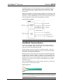
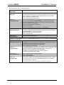
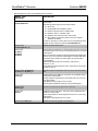
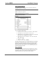
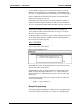
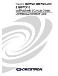
Crestron QM-RX
QuickMedia™ Receiver
Operations Guide
This document was prepared and written by the Technical Documentation department at:
Crestron Electronics, Inc.
15 Volvo Drive
Rockleigh, NJ 07647
1-888-CRESTRON
All brand names, product names and trademarks are the property of their respective owners.
©2005 Crestron Electronics, Inc.
Crestron QM-RX
QuickMedia™ Receiver
Contents
QuickMedia™ Receiver: QM-RX
1
Introduction ..........................................................................................................1
Features and Functions...........................................................................1
QuickMedia Transport System...............................................................2
Part Number Compatibility ....................................................................3
Specifications .........................................................................................4
Physical Description...............................................................................6
Industry Compliance ............................................................................10
Setup...................................................................................................................10
Network Wiring ...................................................................................10
QM Network Wiring ............................................................................12
Installer’s Toolbox ...............................................................................12
Identity Code........................................................................................13
Mounting..............................................................................................16
Hardware Hookup ................................................................................16
Ground Wire Connections....................................................................17
Configuration Software ......................................................................................18
Earliest Version Software Requirements for the PC ............................18
Programming with Crestron SystemBuilder™.....................................19
Configuring with SIMPL Windows .....................................................25
Uploading and Upgrading ..................................................................................33
Communication Settings ......................................................................33
Troubleshooting Communications .......................................................37
Uploading a SIMPL Windows Program ..............................................37
Firmware Upgrade via Installer’s Toolbox ..........................................39
Problem Solving .................................................................................................41
Troubleshooting ...................................................................................41
Further Inquiries...................................................................................42
Future Updates .....................................................................................42
Appendix - QM Auto Compensation..................................................................42
Return and Warranty Policies.............................................................................43
Merchandise Returns / Repair Service .................................................43
CRESTRON Limited Warranty ...........................................................43
Operations Guide – DOC. 6333
Contents ● i
Crestron QM-RX
QuickMedia™ Receiver
QuickMedia™ Receiver: QM-RX
Introduction
Features and Functions
The QM-RX is a QuickMedia™ (QM) receiver designed to provide costeffective RGB and video signal routing and control as part of a complete
MediaManager A/V presentation system. Using Crestron’s exclusive
QuickMedia transport, the QM-RX receives RGB and video signals over a
single inexpensive CAT5E or CAT6 cable from any QuickMedia Wall Plate,
FlipTop Box, QM-TX transmitter, QM Processor, or QM Distribution Center.
Mounted at the projector or plasma display location, the QM-RX breaks out
composite video, S-video, and RGBHV or component signals to feed the
respective inputs on the display device. All signal routing occurs automatically
under the command of the control system based upon the input source type
selected.
The QuickMedia transport supports the transmission of RGB signals with
resolutions up to 1600 x 1200 pixels at 60 Hz. Software-controllable frequency,
bandwidth, and skew compensation adjustments are provided to maximize
image quality with up to 22 nanoseconds (ns) of delay skew.
Functional Summary
Operations Guide – DOC. 6333
•
Programmable logic via SIMPL Windows, including SIMPL+®
•
One bi-directional COM port with programmable serial drivers for
controlling devices over RS-232.
•
One IR port - compatible with Crestron® ST-SPL IR Splitter, for IRcontrol of up to five different devices, programmable via the hundreds
of IR device drivers available in the Crestron databases.
•
One digital input port for direct connection of power sensor, pressure
sensor, door sensor, room occupancy sensor, etc.
•
When used with Crestron RoomView™, provides remote power
control and management of A/V devices, including: monitoring lamp
life of projectors, device status to ensure proper equipment operations,
room occupancy, equipment use log, and device and room security.
•
Composite, S-video and RGBHV output ports.
QuickMedia™ Receiver: QM-RX ● 1
QuickMedia™ Receiver
Crestron QM-RX
The QM-RX includes one bidirectional RS-232 port and one IR/serial port for
control of the display device. A digital input port is also included to enable
direct connection of a room occupancy sensor, power sensor, or any contact
closure device.
Wiring for the QM-RX is extremely simple requiring just one CAT5E or CAT6
cable and one Cresnet® control cable (available together as CresCAT-QM, sold
separately). Complete MediaManager systems can be configured easily to suit a
variety of applications using Crestron SystemBuilder™ software.
Block Diagram of the QM-RX
NOTE: The QM-RX is compatible with 2-Series control systems only.
QuickMedia Transport System
Using a new, proprietary signal routing solution, signals such as composite
video, S-video, RGBHV, audios, and microphone, are all transported using a
single cable solution called QuickMedia (QM).
The QM transport system port is capable of managing computer, video, and
audio signals simultaneously through one CAT5E or CAT6 UTP (unshielded
twisted pair) wire, simplifying installations.
Routing CAT5E or CAT6 UTP cable is less expensive and much simpler than
routing multi-colored, multi-conductor coax cable. All Crestron products using
the QM transport system are capable of sending and receiving QM signals via
standard CAT5E or CAT6 cable. Installation of any QM device is as simple as
installing one set of QM wires from output to input. Installations are flexible,
affordable, and fast.
The Crestron QuickMedia cable “CRESCAT-QM” contains one CAT5E cable
and one Cresnet® cable in siamese jackets.
CRESCAT-QM Cable
NOTE: Do not untwist the two wires in a single pair for more than 1/3-1/2"
(0.84 – 1.27 cm) when making a connection. The twists are critical to canceling
out interference between the wires.
2 ● QuickMedia Receiver: QM-RX
Operations Guide – DOC. 6333
Crestron QM-RX
QuickMedia™ Receiver
The QuickMedia transport mechanism performs delay compensation on each
video input to compensate for signal skew, and frequency/bandwidth
compensation for cable length. Signal skew occurs when part of the signal is
delayed with respect to other signal components. The amount of skew largely
depends on the length and the design of the wire. Because CAT5 consists of
twisted pairs that are twisted together in the cable, unequal wire lengths are
created.
The maximum aggregate cable length from QM transmitter to QM receiver is
limited by the loss of bandwidth over long distances and the amount of available
skew compensation. A cable rated at 15 ns of skew per 100 meters (328 ft.)
means that a cable will have no more than a 15 ns difference between the fastest
and slowest RGB signals over 100 meters of cable.
The QM-RX can compensate for a maximum of 22 ns (nanoseconds) of skew.
To determine the allowable maximum length of installed cable, the installer
must first perform a calculation based on the skew rating of the cable.
Skew compensation is primarily relevant to RGB sources; however, any/all
video or VGA signals may experience a loss of quality over very long lengths of
cable. This phenomenon is due to the added resistance and capacitance of longer
cable lengths, and is not particular to either Crestron and/or QuickMedia
systems. To ensure sufficient bandwidth to support signal resolutions up to
1600 x 1200, the maximum aggregate cable length should not exceed 328 feet.
The use of lower -resolution signals may allow increased cable length but must
be tested by the installer with the sources to be used. Refer to page 12 for
additional QuickMedia network wiring information.
The pin assignment is based on the EIA/TIA 568B RJ-45 Jack standard. The
following table illustrates how composite, S-video, and RGB video signals are
transmitted over the CAT5E wire.
RJ-45 QuickMedia Connector Pin and Pair Assignment
RJ-45 PIN
NUMBER
WIRE COLORS
1
WHITE/ORANGE
- RGB RED
- CHROMINANCE
2
ORANGE
+ RGB RED
+ CHROMINANCE
3
WHITE/GREEN
- RGB GREEN
- LUMINANCE
4
BLUE
+ AUDIO
+ AUDIO
5
WHITE/BLUE
- AUDIO
- AUDIO
6
GREEN
+ RGB GREEN
+ LUMINANCE
7
WHITE/BROWN
- RGB BLUE
- COMPOSITE
8
BROWN
+ RGB BLUE
+ COMPOSITE
(EIA 568B)
QM ASSIGNMENT
RGB AND AUDIO
QM ASSIGNMENT
COMPOSITE,
S-VIDEO AND AUDIO
Part Number Compatibility
Due to production changes, some earlier QM-WMC devices are not compatible
with QM-RX devices.
To ensure compatibility between a QM-RX and QM-WMC, the QM-WMC Part
Number must be 6002423 or above.
NOTE: Part numbers can be found on the silver label affixed to each device.
If you have a part that is not compatible with your existing equipment, contact a
Crestron customer service representative for replacement information.
Operations Guide – DOC. 6333
QuickMedia™ Receiver: QM-RX ● 3
QuickMedia™ Receiver
Crestron QM-RX
Specifications
Specifications for the QM-RX are given in the following table.
QM-RX Specifications
SPECIFICATION
DETAILS
Cresnet Power Usage
8 W (0.33 A @ 24 VDC)
Default Cresnet ID
05
Firmware Version
2.17 or later
2-Series Control
1,2
System Update Files
Version 3.125.CUZ or later
Ports/Connectors
QM
One QuickMedia 8-wire RJ-45 input port
Connects via CAT5E or CAT6 to a QM output port of another
QuickMedia device (Refer to the note following the
specifications table)
Cresnet
One 4-pin 3.5 mm detachable terminal block. Connects to
Cresnet control network
Computer Video
One female DB15HD connector for RGB (VGA)/Component
video output
Supported formats: RGBHV, RGBS, RGsB, YPbPr.
EDTV/HDTV: 480p, 720p, 1080i
Nominal Output Voltage: 0.7 V p-p (RGB, PB PR), 1 V p-p (GS,Y)
H and V Sync: 5.0 V p-p nominal
Output Impedance: 75 ohms (R/G/B), 100 ohms (H/V)
S-Video
One mini-DIN connector for Y/C S-video output.
Nominal Output Voltage: 1.0 V p-p (luma), 0.7 V p-p (chroma).
Output Impedance: 75 ohms
Composite
One BNC connector for composite video output
Nominal Output Voltage: 1.0 V p-p
Output Impedance: 75 ohms
COM
One DB9 bidirectional male serial port (RS-232) baud rate up
to 9600. Hardware and software handshaking support
Infrared – Serial Input
One 2-pin 3.5 mm detachable terminal block. IR output up to
1.2 MHz. 1-way serial TTL/RS-232 (0-5 V) up to 115k baud
Expandable via ST-SPL to control multiple disparate devices
INPUT
One 2-pin 3.5mm detachable terminal block digital input port
(referenced to GND). Rated for 0-24 VDC. Input Impedance:
20 K ohms; Logic Threshold: 2.5 VDC nominal
RGB
Gain
0 dB (75 ohm termination)
Maximum
Resolution and
Refresh Rate
1600 x 1200 @ 60 Hz (at unity gain) With cable length of
100 meters and maximum compensation
Maximum CAT5E/6
Cable Delay Skew
22 ns per 100 meters
Bandwidth
Compensation
(Peak)
Digital control, 10-bit D/A
Low Frequency
Compensation
(Boost)
Digital control, 10-bit D/A
Propagation Delay
Compensation
(Skew)
Digitally controlled delay line, 4-bit, 0-22 ns
(independently for R, G, and B)
Continued on the following page
4 ● QuickMedia Receiver: QM-RX
Operations Guide – DOC. 6333
Crestron QM-RX
QuickMedia™ Receiver
QM-RX Specifications (continued)
SPECIFICATION
DETAILS
Video
Gain
Crosstalk
0 dB (75 ohm termination)
-60 dB
Environmental
Temperature
41° to 104°F (5° to 40°C)
Environmental Humidity
10% to 90% RH (non-condensing)
Dimensions & Weight
Height:
Width:
Depth:
Weight:
Available Accessories
MK-QM-RMCRX Pole Mounting Kit
CNSP-XX Custom Serial Interface Cable
IRP2 IR Probe
ST-SPL Infrared (IR) Splitter (requires CNSP-112)
ST-MB "Master Blaster" Infrared (IR) Sprayer
(requires CNSP-112)
1.71 in (4.34 cm)
6.81 in (17.30 cm)
5.83 in (14.81 cm)
1.10 lb (0.50 kg)
1. The latest software versions can be obtained from the Downloads | Software Updates section of
the Crestron website. Refer to the NOTE following these footnotes.
2. Crestron 2-Series control systems include the AV2 and PRO2. Consult the latest Crestron Product
Catalog for a complete list of 2-Series control systems.
NOTE: Crestron software and any files on the website are for Authorized
Crestron dealers and Crestron Authorized Independent Programmers (CAIP)
only. New users may be required to register to obtain access to certain areas of
the site (including the FTP site).
NOTE: The CAT5E or CAT6 cable must have a delay skew of less than 22 ns
per 100 meters for use with the QuickMedia transport. Purchase CresCAT-QM
for the most cost-effective cabling solution. For plenum applications, use
CresCAT-QM-P. Maximum aggregate cable length is approximately 300 feet
from QM transmitter to QM receiver. A maximum of two QM distribution
centers may be inserted in-line (refer to page 12).
Operations Guide – DOC. 6333
QuickMedia™ Receiver: QM-RX ● 5
QuickMedia™ Receiver
Crestron QM-RX
Physical Description
The QM-RX is housed in a black enclosure with labels on the front and rear
panels. There are three LEDs on the front of the unit for indicating the unit’s
current status. All connections, except for the Cresnet and QuickMedia
connections, are made on the back of the unit. There are four rubber feet on the
base of the unit for stability and to prevent slippage. Refer to the following
physical views.
Front View
Rear View
6 ● QuickMedia Receiver: QM-RX
Operations Guide – DOC. 6333
Crestron QM-RX
QuickMedia™ Receiver
QM-RX Physical Dimensions
Indicators
The QM-RX front panel indicators are described as follows.
PWR (Power)
This green LED illuminates when the unit is connected to Cresnet and receives
24 VDC.
NET
This yellow LED illuminates when the QM-RX communicates with any device
on the network.
Operations Guide – DOC. 6333
QuickMedia™ Receiver: QM-RX ● 7
QuickMedia™ Receiver
Crestron QM-RX
Front Panel Ports
The QM-RX front panel ports are illustrated and described as follows.
1
QM
QM (Input)
8
The 8-pin RJ-45 QuickMedia transport port accepts CAT5E or CAT6 video
and control signals. The QM input port conforms to the 568B wiring standard.
Refer to page 2 and page 12 for additional QuickMedia wiring information.
NOTE: To determine the location of pin 1 on an RJ-45 male connector, hold
the connector with the cable down and the clip facing away from you. Pin 1 is
on the far left.
NET
The four-pin 5 mm detachable terminal block NET connector is used for
connection to Cresnet and expansion to other peripherals.
Pins 24 and G provide 24 VDC and ground.
Pins Y and Z provide communications (data).
Power to the unit (8 W) is supplied through this connector.
Rear Panel Ports
The QM-RX rear panel ports are illustrated and described as follows.
1
RGBHV
10
RGBHV
One DB15HD female connector is provided for RGB video output.
DB15HD Connector Pinout
15
8 ● QuickMedia Receiver: QM-RX
PIN
DESCRIPTION
PIN
DESCRIPTION
1
Red Signal
9
2
Green Signal
10
N/C
Sync Ground
3
Blue Signal
11
N.C.
4
Reserved
12
Pullup
5
Ground
13
Horizontal Sync
6
Red Ground
14
Vertical Sync
7
Green Ground
15
Pullup
8
Blue Ground
Operations Guide – DOC. 6333
Crestron QM-RX
QuickMedia™ Receiver
RGBHV is a computer signal that uses the standard High Density (HD-15)
15-pin connector. It is comprised of three analog video signals: red, green, blue
and separate horizontal and vertical syncs. Most computer monitors use RGB
(usually called VGA, SVGA, XVGA, etc.).
S-VIDEO
S-VIDEO
One DIN type connector for S-video output.
Pin 4
Pin 3
Pin 2
Pin 1
S-Video Connector Pinout
PIN
DESCRIPTION
1
Ground
2
Ground
3
Luminance
4
Chrominance
S-video contains two separate components, luminance and chrominance (also
known as Y and C signals respectively). The luminance signal contains
brightness, intensity, and signal timing information. This signal contains all
picture information except for color. The chrominance signal contains only the
color information. You can see the complete black and white image, without
the chrominance, by only feeding the luminance signal into a monitor.
VIDEO
VIDEO (Composite)
One BNC type connector for composite video output.
Composite video is a type of video signal in which all information – the red,
green, and blue (horizontal and vertical sync) signals are mixed together.
Pin 1
COM
COM
This DB9 (male) software programmable, bidirectional serial port is available
for RS-232 communication, with hardware and software handshaking and
modem control. Speeds are rated up to 9600 bps.
Pin 9
A null modem cable is required to connect to a computer. Refer to the
following table for pinout designations.
Standard COM DB9 Pinout
PIN
Operations Guide – DOC. 6333
DIRECTION
DESCRIPTION
2
To QM-RX
(RXD) Receive Data
3
From QM-RX
(TXD) Transmit Data
4
From QM-RX
(DTR) Data Terminal Ready
5
Common
(SG) Signal Ground
6
To QM-RX
(DSR) Data Set Ready
7
From QM-RX
(RTS) Request To Send
8
To QM-RX
(CTS) Clear To Send
QuickMedia™ Receiver: QM-RX ● 9
QuickMedia™ Receiver
Crestron QM-RX
IR
A 2-position terminal block connector is a mini-implementation of a single
PRO2 IR port. The output is labeled S (signal) and G (ground). Infrared output
is rated up to 1.2 MHz, at data rates up to 115k baud. Serial protocols include
one-way RS-232.
INPUT
This 2-pin terminal block connector provides one software programmable
digital input. The input is a Schmidt trigger type (nominal 2.5 V threshold)
with 24 V input tolerance.
The digital input is rated 0 – 24 VDC, 20 K ohms input impedance.
SETUP LED and Pushbutton
The QM-RX is TouchSettable ID (TSID) ready. The SETUP pushbutton and its
associated LED are located on the front of the unit and are used for setup of the
QM-RX network ID during the initial configuration of a Cresnet system or when
the device is being added or replaced.
Industry Compliance
As of the date of manufacture, the QM-RX has been tested and found to comply
with specifications for CE marking and standards per EMC and
Radiocommunications Compliance Labelling.
NOTE: This device complies with part 15 of the FCC rules. Operation is
subject to the following two conditions: (1) this device may not cause harmful
interference, and (2) this device must accept any interference received, including
interference that may cause undesired operation.
Setup
Network Wiring
CAUTION: In order to ensure optimum performance over the full range of
your installation topology, Crestron Certified Wire, and only Crestron Certified
Wire, should be used. Failure to do so, may incur additional charges if support is
required to identify performance deficiencies as a result of using improper wire.
CAUTION: Provide sufficient power to the system. Insufficient power can lead
to unpredictable results or damage to the equipment. Please use the Crestron
Power Calculator to help calculate how much power is needed for the system
(http://www.crestron.com/calculators).
CAUTION: Use only Crestron power supplies for Crestron equipment. Failure
to do so could cause equipment damage or void the Crestron warranty.
10 ● QuickMedia Receiver: QM-RX
Operations Guide – DOC. 6333
Crestron QM-RX
QuickMedia™ Receiver
NOTE: When installing network wiring, refer to the latest revision of the
wiring diagram(s) appropriate for your specific system configuration, available
from the Crestron website.
When calculating the wire gauge for a particular Cresnet run, the length of the
run and the Cresnet power usage of each network unit to be connected must be
taken into consideration. If Cresnet units are to be daisy-chained on the run, the
Cresnet power usage of each unit to be daisy-chained must be added together to
determine the Cresnet power usage of the entire chain. If the unit is a home-run
from a Crestron system power supply network port, the Cresnet power usage of
that unit is the Cresnet power usage of the entire run. The length of the run in
feet and the Cresnet power usage of the run should be used in the resistance
equation below to calculate the value on the right side of the equation.
Resistance Equation
The required wire gauge should be chosen such that the resistance value is less
than the value calculated in the resistance equation. Refer to the following table.
Wire Gauge Values
RESISTANCE
WIRE GAUGE
4
16
6
18
10
20
15
22
13
Doubled CAT5
8.7
Tripled CAT5
NOTE: All Cresnet wiring must consist of two twisted pairs. One twisted pair
is the +24V conductor and the GND conductor, and the other twisted pair is the
Y conductor and the Z conductor.
NOTE: When daisy-chaining Cresnet units, strip the ends of the wires carefully
to avoid nicking the conductors. Twist together the ends of the wires that share a
pin on the network connector, and tin the twisted connection. Apply solder only
to the ends of the twisted wires. Avoid tinning too far up the wires or the end
becomes brittle. Insert the tinned connection into the Cresnet connector and
tighten the retaining screw. Repeat the procedure for the other three conductors.
NOTE: For additional information on video connections over CAT5, refer to
the latest version of the Crestron CAT5 Wiring Reference Guide (Doc. 6137)
which is available from Crestron website (http://www.crestron.com/manuals).
NOTE: For larger networks (i.e., greater than 28 network devices), it may be
necessary to add a Cresnet Hub/Repeater (CNXHUB) to maintain signal quality
throughout the network. Also, for networks with lengthy cable runs or varying
types of network devices, it may be desirable to add a hub/repeater after only 20
network devices.
Operations Guide – DOC. 6333
QuickMedia™ Receiver: QM-RX ● 11
QuickMedia™ Receiver
Crestron QM-RX
QM Network Wiring
For the QuickMedia transport, use CRESCAT-QM.
The aggregate cable length from transmitter to receiver cannot have a delay
skew of more than 22 ns for a given signal path originating at a QM transmitter
and terminating at a QM receiver. The aggregate cable length must not exceed
328 feet.
When connecting multiple QM devices, the route between a QM origination
point (transmitter) and a QM endpoint (receiver) cannot have more than two
midpoints (e.g., QM-MD7x2 or other QM switchers). Refer to the following
diagram when configuring a QM network.
QM Network Topology
Installer’s Toolbox
The Installer's Toolbox (replacement for Crestron Viewport, you may continue
use Viewport if desired) is a broad-based software package that accomplishes
multiple system tasks, primarily using an RS-232 or TCP/IP connection between
a PC and one or more Crestron control systems.
You can use the Installer's Toolbox to:
•
Observe system processes.
•
Upload operating systems and firmware.
•
Upload programs and touchpanel projects.
•
Set or change device Network IDs.
•
Change serial numbers.
•
Run scripts to automate tasks.
•
Perform system diagnostics, and much more.
The Installer's Toolbox allows you to perform these functions using simple
graphical views and click and drag methods.
12 ● QuickMedia Receiver: QM-RX
Operations Guide – DOC. 6333
Crestron QM-RX
QuickMedia™ Receiver
Identity Code
Every equipment and user interface within the network requires a unique
identity code (Net ID). These codes are two-digit hexadecimal numbers from 03
to FE. The Net ID of each unit must match an ID code specified in the SIMPL
Windows program. Refer to “Setting the Net ID in Device Settings” on page 26
for details of the SIMPL Windows procedure.
The Net ID of the QM-RX has been factory set to 05. The Net IDs of multiple
QM-RXs in the same system must be unique. Net IDs are changed from a
personal computer (PC) via the Crestron Installer’s Toolbox.
NOTE: For detailed information on establishing communication between the
PC, control system, and the QM-RX, refer to “Communication Settings” on
page 33. If communication cannot be established, refer to the “Troubleshooting
Communications” section in the latest version of the 2-Series Control System
Reference Guide (Doc. 6256), which is available from the Crestron website.
The Installer's Toolbox provides several methods to easily set or change device
Net IDs for any device on the network. The following method permits you to
change the Net ID of any device in the network through the “Network Device
Tree” window.
NOTE: This method prevents you from setting duplicate IDs.
This method permits you to manually set the Net ID for any device in the
network, can be used to set any known Net IDs that may require changing, and
may also be used for non-TSID equipment. This method will not permit you to
choose an ID already in use by another device. A warning message will appear
if you attempt to use an ID that is already in use.
Duplicate Net ID Warning Message
This method does not change the Net ID as assigned in SIMPL windows.
NOTE: You may also use SystemBuilder to perform Network ID setup. Refer
to page 24 for Net ID setup details using SystemBuilder.
Operations Guide – DOC. 6333
1.
Ensure that all network devices are connected to the control system.
2.
Open Installer’s Toolbox and select the Network Device Tree
icon, or select Tools | Network Device Tree.
3.
Select the connection using the pull down list or click “Click here to
select connection…” to open the address book.
QuickMedia™ Receiver: QM-RX ● 13
QuickMedia™ Receiver
Crestron QM-RX
Network Device Tree – Pull Down Connection List
4.
Select the connection (TCP or serial) and click OK.
Network Device Tree – Address Book
5.
14 ● QuickMedia Receiver: QM-RX
The Network Device Tree displays all devices on the current network.
Operations Guide – DOC. 6333
Crestron QM-RX
QuickMedia™ Receiver
Installer’s Toolbox – Network Device Tree
6.
Right-click on the device Net ID, and when the sub-menu appears,
select Change Network ID from the sub-menu.
Network Device Tree – Sub-Menu
7.
Enter a new Net ID and press Enter.
Enter New Net ID
Operations Guide – DOC. 6333
QuickMedia™ Receiver: QM-RX ● 15
QuickMedia™ Receiver
Crestron QM-RX
Repeat this procedure for each additional network device requiring a Net ID
change.
Mounting
The QM-RX can be mounted using the included four mounting brackets. Each
bracket measures 1.6 in long, 0.5 in wide and 0.75 in high. Attach the included
four brackets using the existing cover screws located on the sides of the QM-RX
as shown in the following diagram.
Mounting Positions of the Four Included Mounting Brackets
NOTE: The MK-QM-RMCRX mounting kit is available for mounting the
QM-RX to a pipe. Details can be found in the latest version of the
MK-QM-RMCRX Installation Guide (Doc. 6247), available from the Crestron
website.
Hardware Hookup
Refer to the following hookup diagram and, aside from attaching power last,
complete the connections in any order.
NOTE: To prevent overheating, do not operate this product in an area that
exceeds the environmental temperature range listed in the specifications table.
Consideration must be given if installed in a closed or multi-unit rack assembly
since the operating ambient temperature of the rack environment may be greater
than the room ambient. Contact with thermal insulating materials should be
avoided on all sides of the unit.
16 ● QuickMedia Receiver: QM-RX
Operations Guide – DOC. 6333
Crestron QM-RX
QuickMedia™ Receiver
NOTE: The maximum continuous current from equipment under any external
load conditions shall not exceed a current limit that is suitable for the minimum
wire gauge used in interconnecting cables. The ratings on the connecting unit's
supply input should be considered to prevent overloading the wiring.
QM-RX Hookup
Ground Wire Connections
Proper grounding is required. Connect the ground from the QM-RX to earth
ground. Connect the Cresnet shield lead at the control processor to the ground
lead. The control processor chassis must also be connected to an earth ground
(building steel). Refer to the following grounding diagram.
Ground Wire Connections
NOTE: Do not connect the shield to earth ground at the QM-RX
Operations Guide – DOC. 6333
QuickMedia™ Receiver: QM-RX ● 17
QuickMedia™ Receiver
Crestron QM-RX
Configuration Software
Have a question or comment about Crestron software?
Answers to frequently asked questions (FAQs) can be viewed in the Online Help
section of the Crestron website. To post a question or view questions you have
submitted to Crestron’s True Blue Support, log in at http://support.crestron.com.
First-time users will need to establish a user account.
Configuration is easy thanks to Crestron’s Windows-based programming
software. Crestron SystemBuilder software creates a complete project, with no
special programming required. SystemBuilder completes all necessary
programming for a base system including all touchpanel screens and the control
system program. The program output of SystemBuilder is a SIMPL Windows
program with much of the functionality encapsulated in macros and templates.
Once SystemBuilder creates the project, the system interfaces and program logic
can be customized in SystemBuilder or can be easily modified with Crestron
development tools, i.e., SIMPL Windows and Crestron VisionTools Pro-e (VT
Pro-e) software packages.
SystemBuilder comes with templates for all supported interfaces. If a user
wishes to create a touchpanel project using templates with a different look-andfeel, this can be accomplished by making a custom template. This custom
template can then be used by SystemBuilder to create the final project files to be
loaded into the panels. Alternatively, VT Pro-e can be used to tweak projects
created with the SystemBuilder or develop original touchpanel screen designs.
Earliest Version Software Requirements for the
PC
NOTE: Crestron recommends that you use the latest software to take advantage
of the most recently released features. The latest software is available from the
Crestron website
NOTE: Crestron software and any files on the website are for Authorized
Crestron dealers and Crestron Authorized Independent Programmers (CAIP)
only. New users are required to register to obtain access to certain areas of the
site (including the FTP site).
The following are the earliest useable software version requirements for the PC:
18 ● QuickMedia Receiver: QM-RX
•
SIMPL Windows version 2.06 or later, Library 322 and SIMPL+ Cross
Compiler version 1.1.
•
Crestron Database version 16.4.0 or later. Required by SIMPL
Windows.
•
Installer’s Toolbox version 1.0 or later.
•
(Optional but highly recommended) SystemBuilder version 2.0.
SystemBuilder 2.0 will require later versions of the following software
programs: SIMPL Windows, Library, VT Pro-e, Crestron database,
and Crestron Engraver.
Operations Guide – DOC. 6333
Crestron QM-RX
QuickMedia™ Receiver
Programming with Crestron SystemBuilder™
The easiest method of
programming, but does not
offer as much flexibility as
SIMPL Windows.
Crestron SystemBuilder offers automatic programming for such residential and
commercial applications as audio distribution, home theater, video conferencing, and
lighting. The interface of this tool guides you through a few basic steps for
designating rooms and specifying the control system, touchpanels, devices, and
functionality. Crestron System Builder then programs the system, including all
touchpanel projects and control system logic.
Crestron SystemBuilder is fully integrated with Crestron's suite of software
development tools, including SIMPL Windows, VT Pro-e, Crestron Database,
User IR Database, and User Modules Directory. Crestron System Builder
accesses these tools behind the scenes, enabling you to easily create robust
systems.
NOTE: Modifications to the program that are made outside of SystemBuilder
(for example, in VT Pro-e or SIMPL Windows) are not preserved when you
reenter SystemBuilder.
SystemBuilder
After entering the appropriate information in each step, SystemBuilder creates
the control system logic and touchpanel pages, ready to upload to the controller.
NOTE: Crestron SystemBuilder version 2.0 or higher is required.
The following information is a general procedure for setting up a QuickMedia
system using SystemBuilder. Refer to the SystemBuilder help file for more
detailed instructions.
Operations Guide – DOC. 6333
QuickMedia™ Receiver: QM-RX ● 19
QuickMedia™ Receiver
Crestron QM-RX
Creating a QuickMedia System in SystemBuilder
1.
Open SystemBuilder and select File | New. Select a Blank System.
SystemBuilder – New Blank System
2.
Select the plug-in for a QuickMedia system.
SystemBuilder – Plug-in Selection
3.
20 ● QuickMedia Receiver: QM-RX
Select the control processor.
Operations Guide – DOC. 6333
Crestron QM-RX
QuickMedia™ Receiver
SystemBuilder – Select a Control Processor
4.
Specify the audio configuration.
5.
Add RoomView™ if desired.
6.
and
Click the Assign QuickMedia Devices and Routing button
drag the QM-RX from the library on the right side, to the QM system
on the left side.
SystemBuilder – My Crestron System
Operations Guide – DOC. 6333
7.
Setup QM network cable routing.
8.
Build the program.
9.
Upload the program to the control processor.
QuickMedia™ Receiver: QM-RX ● 21
QuickMedia™ Receiver
Crestron QM-RX
10. Use the Realtime view to perform the video adjustments.
SystemBuilder – System View
Video Adjustments
NOTE: The use of SIMPL Windows to setup video is not recommended.
SystemBuilder software is also used to adjust the video peaking, boost, and
skew of a QM system.
SystemBuilder Video Adjustments
22 ● QuickMedia Receiver: QM-RX
Operations Guide – DOC. 6333
Crestron QM-RX
QuickMedia™ Receiver
The first bitmap (for Steps 1 and 2) consists of lines of black text on gray and
white backgrounds, and lines of blue text on gray and white backgrounds. You
may also browse for your own bitmap test image.
Text Test Pattern
Step 1 – If the text is blurred and the text color persists (smears) into the blank
space after the text, this is "black streaking" and you need to increase the
peaking value. If you see white bands persisting after the text or you see small
white areas after the text, you have "white streaking" and you need to decrease
the peaking value.
Black and White Streaking
Step 2 – If you see "blooming" or pixel areas that appear larger than normal, you
need to decrease the boost.
Step 3 – The QM skew bitmap consists of two sets of three vertical lines of red,
green and blue positioned directly over one another. The amount of skew is
determined by observing which line is shifted farthest to the right. The line
farthest to the right has the most skew delay. Adjust the other two lines by
increasing their skew so that they all line up. In the following example, increase
red and blue to match green.
Skew Test Pattern
For additional details, download SystemBuilder from the Crestron website and
examine the extensive help file.
Operations Guide – DOC. 6333
QuickMedia™ Receiver: QM-RX ● 23
QuickMedia™ Receiver
Crestron QM-RX
Setting Net IDs in SystemBuilder
SystemBuilder provides a convenient method of selecting and assigning Net IDs
to devices.
1.
Ensure that all network devices are connected to the control system.
2.
After completing your SystemBuilder program, click the Build and
Upload button
.
SystemBuilder – Finish Window
3.
On the Finish window, click the Set Network IDs… button to assign
the network IDs. SystemBuilder provides three methods for assigning
Net IDs.
•
Drag and drop a device from the program tree on the left onto the
device in the network tree on the right.
•
Right-click a device the program tree on the left and select Setup
from the sub-menu.
•
Right-click on a device in the network tree on the right and set the
Net ID directly.
SystemBuilder – Set Network ID Window
24 ● QuickMedia Receiver: QM-RX
Operations Guide – DOC. 6333
Crestron QM-RX
QuickMedia™ Receiver
Configuring with SIMPL Windows
NOTE: The following are acceptable file extensions for programs that include
a QM-RX, developed for specific control system types:
.smw projectname.smw (source file)
.spz projectname.spz (compiled file for 2-Series)
.usp projectname.usp (source code module for SIMPL+)
.ir
projectname.ir (user IR)
.umc projectname.umc (user macro)
.ush projectname.ush (completed SIMPL+)
SIMPL Windows is the Crestron graphical, Windows®-based development tool
for programming control systems. The SIMPL Windows interface provides two
workspaces: the Configuration Manager, for configuring the control system,
touchpanels, and controlled network devices; and Program Manager, for
designing the logic and functionality of the control system.
In addition, you can use the powerful Installer’s Toolbox utility to accomplish
multiple system tasks, such as uploading the program to the control system and
performing diagnostic functions.
NOTE: The information in this section assumes that the reader has knowledge
of SIMPL Windows. If not, refer to the extensive help information provided
with the software.
NOTE: The QM-RMCRX control system is used in the following descriptions.
This section describes a sample SIMPL Windows program that includes a
QM-RX.
Configuration Manager is where programmers “build” a Crestron control system
by selecting hardware from the Device Library. In Configuration manager, drag
the QM-RMCRX from the Control Systems folder of the Device Library and
drop it in the upper pane of the System Views. The QM-RMCRX with its
associated communication ports is displayed in the System Views upper pane.
QM-RMCRX System View
The System Views lower pane displays the QM-RMCRX system tree (refer to
the following graphic). This tree can be expanded to display and configure the
communication ports.
Operations Guide – DOC. 6333
QuickMedia™ Receiver: QM-RX ● 25
QuickMedia™ Receiver
Crestron QM-RX
Expanded QM-RMCRX System Tree
C2Net-Device Slot in Configuration Manager
To incorporate a QM-RX into the system, drag the QM-RX from the Cresnet
Control Modules | QM Series folder of the Device Library and drop it in System
Views. The QM-RMCRX system tree displays the QM-RX in Slot 5, with a
default Net ID of 05 as shown in the following illustration.
QM-RX in Slot 5 of the QM-RMCRX
NOTE: The first QM-RX in a system is preset with a Net ID of 05 when its
symbol is dragged into the upper pane of System Views. Additional units are
assigned different Net ID numbers as they are added.
Setting the Net ID in Device Settings
Double-click the QM-RX icon in the upper pane to open the “Device Settings”
window. This window displays QM-RX device information. The Net ID can be
changed in this window using the Net ID tab, as shown in the following figure.
“Device Settings” Window
26 ● QuickMedia Receiver: QM-RX
Operations Guide – DOC. 6333
Crestron QM-RX
QuickMedia™ Receiver
NOTE: This procedure sets the Net ID for the QM-RX in the program only. It
does not automatically set the Net ID for the QM-RX itself. SIMPL Windows
automatically changes Net ID values of a device added to a program if a
duplicate device or a device with the same Net ID already exists in the program.
Always ensure that the hardware and software settings of the Net ID match. For
Net ID hardware setting details, refer to “Identity Code” on page 12.
QM-RX Symbol in Programming Manager
Programming Manager is where programmers “program” a Crestron control
system by assigning signals to symbols. Click the plus sign of the QM-RX to
reveal the two available slots, each with its own symbol. In Program Manager,
expand the QM-RX to view the individual sub-slots; then drag the desired
symbol to Detail View. The QM-RX sub-slots and corresponding symbols are
described in the following paragraphs. Table defining the input and output
signals follow each section.
QM-RX Slots
Slot 1: C2I-QMRX-VIDEO
The first slot contains the video control module. The video module selects the
video source, sends it to the proper output, saves and recalls skew presets, and
adjusts peaking and boost.
Operations Guide – DOC. 6333
QuickMedia™ Receiver: QM-RX ● 27
QuickMedia™ Receiver
Crestron QM-RX
Detail View of Video Output Control
The QM-RX provides integrated skew compensation, which corrects problems
such as color separation that can occur when CAT5 cables have variations in the
pair lengths. Delay skew is the difference in time (measured in nanoseconds)
between the fastest and slowest pairs of a cable for a signal to travel from one
end of the cable to the other. To correct delay skew, the red, green and blue
skew presets inputs add delay to the faster pairs, allowing the video signals to be
presented in synchronization.
NOTE: The skew, peaking and boost signals should be set through
SystemBuilder software while viewing the video test patterns. The explanations
presented here are for completeness of information.
Video Source Relationships
28 ● QuickMedia Receiver: QM-RX
RGB
COMPONENT
S-VIDEO
COMPOSITE
Red
PR
(C) Chrominance
-
Green
Y
(Y) Luminance
-
Blue
PB
-
Composite
Operations Guide – DOC. 6333
Crestron QM-RX
QuickMedia™ Receiver
QM-RX Sub-Slot 01: Video Control Module Signals
SIGNAL TYPE
AND NAME
DESCRIPTION
Digital output
<QM_Link>
Indicates that the connection with the transmitter is present and valid. The output
will remain high for as long as the connection to the input is valid. This signal will
indicate a failure if, for example, the QM cable is disconnected or damaged.
High/1 = Connection valid at the input
Low/0 = Connection broken at the input
Digital input
<SaveSkewPreset>*
Saves the three R/G/B skew values, together with the peak and boost values, into
the preset number given by <SkewPreset#_F> when the input is held high.
If the save is asserted at the same time as a recall, the recall operation takes
precedence and the save is ignored.
High/1 (level sensitive) = Save skew preset
Low/0 = No preset save
All save and recall inputs are level sensitive, not edge-triggered.
Digital input
<RecallSkewPreset>*
[*This signal is operative only if automatic video compensation is NOT enabled.]
Recalls the R/G/B skew values and peak/boost values stored in the preset given
by <SkewPreset#> when the input is held high.
High/1 (level sensitive) = Recall skew preset
Low/0 = No preset recall
Digital Output
<SkewPreset#_F>
Reports the Skew Preset Number.
NOTE: When <SaveSkewPreset> is high and <RecallSkewPreset> is high, then a change in <SkewPreset#>
will trigger a recall action.
Digital input
<EnableVideoAutoComp>
The <EnableVideoAutoComp> digital signal enables automatic video
compensation for as long as the input is high. Refer to the Appendix on page 42
for additional information about QM Auto Compensation.
High/1 (level sensitive) = Enable auto-compensation
Low/0 = Disable auto-compensation
Digital input
<ProjFilterEnable>
The <ProjFilterEnable> enables the projector filter for as long as the input is high.
This turns on a built-in out-of-band noise filter module, which improves
performance when connected to certain DLP displays.
This setting is not recommended for high-resolution monitors;
for example UXGA 1600 x1200 or 1080p.
Digital output
<ProjFilterEnable-F>
Reports the status of the projector filter feature.
High/1 = Filter enabled
Low/0 = Filter not enabled
Analog input
<SkewPreset#>*
[*This signal is operative only if automatic video compensation is NOT enabled.]
Sets the skew preset number where the R/G/B/ skew values and peak/boost
values will be saved or recalled.
Valid values range from 1d to 254d. Out of range values are ignored.
Continued on the following page
Operations Guide – DOC. 6333
QuickMedia™ Receiver: QM-RX ● 29
QuickMedia™ Receiver
Crestron QM-RX
QM-RX Sub-Slot 01: Video Control Module Signals (continued)
SIGNAL TYPE
AND NAME
DESCRIPTION
Analog input
<VideoInputSelect>
Selects the video source that will be switched to the corresponding
video output.
Valid analog values range from 0d to 5d as follows:
0d = No source
1d = Switch RGB video to RGBHV output
2d = Switch composite video to VIDEO output
3d = Switch S-video to S-VIDEO output
4d = Displays both composite and S-video output
5d = Not used for programming. Refer to the Tech Support
database for details.
A value of 0 denotes no current video source and disables all video
outputs. No other values are valid for <VideoInputSelect>.
Analog output
<VideoInputSelect_F>
Reports the active video source.
Analog input
<R_Skew>
<G_Skew>
<B_Skew>
Sets the skew compensation, in nanoseconds for the red, green and
blue twisted pairs. These values can be applied directly or saved into
a skew preset.
Skew compensation adjusts for timing delays between twisted pairs
that can occur over long CAT5 cable lengths. The skew adds delay
to the faster pairs, allowing the video signals to be presented in
synchronization.
Valid analog values range from 0d (0ns) to 15d (22.5ns),
where 1d = 1.5ns.
Values below 0d will set the skew to 0ns; values above 15d will set
the skew to 22.5ns.
Analog outputs <R_Skew_F>
<G_Skew_F> <B_Skew_F>
Reports the skew compensation at the red, green and blue twisted
pair.
Analog input
<Peaking>
Applies peaking at the QM input. This value can be applied directly
or saved into a skew preset.
Peaking adjusts for high frequency attenuation that can occur over
long cable lengths.
Valid peaking values range from 0% to 100%.
Recommended peak/boost values for varying cable lengths:
Analog output
<Peaking_F>
Reports the peaking being applied at the QM input.
Analog input
<Boost>
Applies boost at the QM input. This value can be applied directly or
saved into a skew preset.
Boost compensates for overall signal loss that can occur over long
cable lengths.
Valid boost values range from 0% to 100%.
Analog output <Boost_F>
Reports the boost being applied at the QM input.
30 ● QuickMedia Receiver: QM-RX
Operations Guide – DOC. 6333
Crestron QM-RX
QuickMedia™ Receiver
Slot 2: C2I-RX-COM1-232
The C2I-RX-COM1-232 provides one two-way serial driver COM port for
controlling serial devices over RS-232.
NOTE: This port does not support RS-422 or RS-485.
NOTE: C2N-NPA8 is not supported.
NOTE: The [RESERVED] fields are left blank.
Detail View of Two-Way Serial Driver
Two-way serial driver signals include:
•
Serial input for one-way and two-way serial drivers: <tx$> (transmit)
•
Serial output for two-way serial drivers: <rx$> (receive)
•
Digital inputs for two-way serial drivers: <rts> (request to send), <dtr>
(data terminal ready), <long-break> and <break>
•
Digital outputs for two-way serial drivers: <cts> (clear to send), and
<dsr> (data set ready).
•
Digital input: <enable>
•
Parameters: <str1>, <str2>, <delimiter>
The <tx$> (transmit) and <rx$> (receive) signals send and receive serial strings
using whichever communication format, or protocol, the serial device requires.
This protocol is usually described in the manufacturer's documentation and
includes the transmission speed (baud rate), error checking (parity), number of
data bits and stop bits, and any hardware or software handshaking that may be
required to control the flow of data.
Slot 3: C2I-RX-IR1
The C2I-RX-IR1 provides one IR output port for controlling devices via IR or
one-way RS-232. Depending on the control format, additional equipment such
as IR emitters, splitters, receivers, and remote control transmitters may be
required. This symbol is not visible because no detail is required.
Operations Guide – DOC. 6333
QuickMedia™ Receiver: QM-RX ● 31
QuickMedia™ Receiver
Crestron QM-RX
To add an IR device, drag the device from the Crestron, Project, or User IR
Database to the C2I-RX-IR1. The Crestron database contains hundreds of IR
driver files, covering most IR devices on the market today. The IR port requires
one IRP2 (infrared emitter probe) installed on each IR device. One end of the
emitter is installed on or near the IR sensor window of the controlled device
while the other end plugs into the port.
The ST-MB (master blaster) IR sprayer can "spray" IR signals 90 degrees. It
eliminates the need for IR probes and resistors, and can be positioned to reach
all devices. It is designed to handle multiple IR codes so that only one sprayer is
needed for many devices.
NOTE: The C2I-RX-IR1 does not support simultaneous IR and RS-232
control. That is, an IR driver cannot be stacked on the port together with a
one-way serial driver. The control format must be of one type. Use only one
IR driver or one-way serial driver.
In addition, the IR port does not have negative voltage and thus may not provide
the full voltage range required by some RS-232 devices (although nearly all
RS-232 devices will operate properly).
Slot 4: C2I-RX-DI1
Slot 4: C2I-RX-DI1 provides one digital input port for connection of an external
sensor or other contact closure device.
Detail view of the Digital Input Card
The C2I-RX-DI1 provides one digital input port for connection of an external
sensor or other contact closure device.
The signal indicates a drop in voltage to less than 1.1 V. The output remains
high for as long as the voltage reads less than 1.1 V. The input voltage must
change by at least 0.3V in either direction to register a new logic state, which
prevents jitter.
An internal 2K ohm pull-up resistor forces the port to read 5.0V if there is no
external sensor connected.
•
High/1 = Voltage less than 1.1 V
•
Low/0 = Voltage more than 1.1 V or no device connected
Example Programming
An example program for the QM-RX is available from the “Example Program”
section of the Crestron website (http://www.crestron.com/exampleprograms).
32 ● QuickMedia Receiver: QM-RX
Operations Guide – DOC. 6333
Crestron QM-RX
QuickMedia™ Receiver
Uploading and Upgrading
NOTE: Crestron recommends that you use the latest software and that each
device contains the latest firmware to take advantage of the most recently
released features. Please check the Crestron website
(http://www.crestron.com/updates) for the latest versions of software and
firmware. New users are required to register to obtain access to this site.
Assuming a PC is properly connected to the entire system, Crestron
programming software allows the programmer to upload programs, projects and
firmware to the system and touchpanels after their development. However, there
are times when the files for the program and projects are compiled and not
uploaded. Instead, compiled files may be distributed from programmers to
installers, from Crestron to dealers, etc. Even firmware upgrades are available
from the Crestron website as new features are developed after product releases.
In those instances, one has the option to upload via the programming software or
to upload and upgrade via the Crestron Installer’s Toolbox.
The following sections define how one would upload a SIMPL Windows
program to the control system or upgrade the firmware of the QM-RX.
However, before attempting to upload or upgrade, it is necessary to establish
communications.
Communication Settings
NOTE: For laptops and other PCs without a built-in RS-232 port, Crestron
recommends the use of PCMCIA cards, rather than USB-to-serial adapters. If a
USB-to-serial adapter must be used, Crestron has tested the following devices
with good results:
Belkin (large model) F5U103
I/O Gear GUC232A (discontinued)
Keyspan USA-19QW (discontinued)
Other models, even from the same manufacturer, may not yield the same results.
NOTE: Even with these recommended models, results may vary on the
computer being used.
The procedure in this section provides details for RS-232 communication
between the PC and the control system. If TCP/IP communication is preferred,
consult the latest version of the Crestron e-Control Reference Guide (Doc. 6052)
or the respective Operations Guide for the control system. These documents are
available from the Crestron website. Refer to the following figure for a typical
connection diagram when uploading files.
Operations Guide – DOC. 6333
QuickMedia™ Receiver: QM-RX ● 33
QuickMedia™ Receiver
Crestron QM-RX
Typical Connection Diagram when Uploading
NOTE: Use a standard DB9 “Null-Modem” RS-232 cable for communication
with a QuickMedia processor. Use a straight-through cable for communication
with a 2-Series processor.
Serial Connection to the Control Processor
1.
Ensure that all devices are connected to the control processor and the
control processor is connected via serial cable to the PC.
2.
Open Installer’s Toolbox and click Tools | Manage Address Book to
display the communications settings. Enter the new address name, and
then click RS-232 as the connection type.
The PC communication settings specified here should match the
protocol that the control processor expects. The usual settings are as
follows:
34 ● QuickMedia Receiver: QM-RX
•
Port = COM 1 through COM 8. Select the correct COM port on
the PC.
•
Baud rate = 115200.
•
Parity = None.
•
Number of data bits = 8.
•
Number of stop bits = 1.
•
Hardware handshaking (RTS/CTS) enabled.
•
Software handshaking (XON/XOFF) not enabled.
Operations Guide – DOC. 6333
Crestron QM-RX
QuickMedia™ Receiver
Installer’s Toolbox “Address Book” Window – Serial Setup
3.
After setting the correct parameters, click OK to return to the
Installer’s Toolbox main window.
4.
Click Tools | Network Device Tree to display the devices in the
system.
TCPIP Connection to Control Processor
1.
Operations Guide – DOC. 6333
Ensure that all devices are connected to the control processor. For
TCP/IP, use CAT5 straight through cables with 8-pin RJ-45 connectors
to connect the LAN port on the control processor and the LAN port on
the PC to the Ethernet hub. Alternatively, you can use a CAT5
crossover cable to connect the two LAN ports directly, without using a
hub. The following table illustrates pinouts for straight through and
crossover RJ-45 cables. Pins 4, 5, 7, and 8 are not used.
QuickMedia™ Receiver: QM-RX ● 35
QuickMedia™ Receiver
Crestron QM-RX
RJ-45 Straight Through Cable
FROM
PIN
COLOR
SIGNAL
TO
PIN
SIGNAL
1
White/Orange
2
Orange
Tx+
1
Tx+
Tx-
2
Tx-
3
White/Green
6
Green
Rc+
3
Rc+
Rc-
6
Rc-
RJ-45 Crossover Cable
FROM
PIN
COLOR
SIGNAL
TO
PIN
SIGNAL
1
White/Orange
Rc+
3
Tx+
2
Orange
Rc-
6
Tx-
3
White/Green
Tx+
1
Rc+
6
Green
Tx-
2
Rc-
2.
Once the cable connections are made, open Installer’s Toolbox. Click
Tools | Manage Address book to display the “Address Book” window
and enter the new address name. Then click TCP/IP as the connection
type. Enter the IP address or hostname of the control processor.
Installer’s Toolbox “Address Book” Window – TCPIP Setup
36 ● QuickMedia Receiver: QM-RX
3.
After setting the correct parameters, click OK to return to the
Installer’s Toolbox main window.
4.
Click Tools | Network Device Tree to display the devices in the
system.
Operations Guide – DOC. 6333
Crestron QM-RX
QuickMedia™ Receiver
Troubleshooting Communications
Use the following checklist if communication cannot be established with the
control processor.
1.
Verify that you are using the correct cables. As described previously,
an RS-232 connection requires a null modem RS-232 cable. TCP/IP
connection requires a CAT5 cable with 8-pin RJ-45 connectors.
2.
With a serial connection, verify that the correct COM port on the PC
has been selected. Some computers have more than one COM port;
some may be internal (e.g., for a modem). Consult the manufacturer’s
documentation for further information about the COM ports on your
PC.
3.
Remove and reapply power to the control system.
4.
If communication still cannot be established, contact Crestron customer
service.
Uploading a SIMPL Windows Program
A control system source file has
the extension .smw. A compiled
SIMPL Windows file has the
extension .spz for a 2-Series
control system.
The SIMPL Windows file can be uploaded to the control system using SIMPL
Windows or via Installer’s Toolbox.
Upload via SIMPL Windows
1.
Start SIMPL Windows.
2.
Select File | Open to view the “Open” window, navigate to the SIMPL
Window file (.smw), and click Open.
3.
Select Project | Transfer Program.
Upload via Installer’s Toolbox
1.
Verify that the procedure for “Communication Settings” that begins on
page 33 has been performed.
2.
Open Installer’s Toolbox.
3.
Select Tools | System Info.
Installer’s Toolbox – Tools | System Info
Operations Guide – DOC. 6333
QuickMedia™ Receiver: QM-RX ● 37
QuickMedia™ Receiver
Crestron QM-RX
4.
When the “System Info” window appears, the Functions option
becomes available from the menu bar.
5.
Select Functions | SIMPL Program.
6.
The “SIMPL Program” window contains information about the
currently loaded SIMPL program (if any), and permits you to stop,
start, erase, retrieve, and upload a SIMPL program. This menu also
permits you to upload to compact flash or internal flash.
“SIMPL Program” Window
7.
Click the
button to browse for a new compiled (.spz) program.
“Open” Window
8.
38 ● QuickMedia Receiver: QM-RX
Select a file and click Open. When the SIMPL Program window reopens click Send.
Operations Guide – DOC. 6333
Crestron QM-RX
QuickMedia™ Receiver
Firmware Upgrade via Installer’s Toolbox
To take advantage of all the QM-RX features, it is important that the unit
contains the latest firmware available. Please check the Crestron website for the
latest version of firmware. Not every product has a firmware upgrade, but as
Crestron improves functions, adds new features, and extends the capabilities of
its products, firmware upgrades are posted. To upgrade the firmware, complete
the following steps.
1.
Make sure that “Communication Settings,” which begins on page 33,
has been performed.
2.
Open Installer’s Toolbox.
3.
Open the Network Device Tree (the firmware upgrade function is also
available in the SMW Program Tree window).
4.
Right-click on the device and select Functions | Firmware.
Network Device Tree Window – Right-Click Sub Menu
5.
The “Firmware” window displays the model and current firmware
version. Click Upload New Firmware.
“Firmware” Window
6.
Operations Guide – DOC. 6333
When the following screen appears, browse to locate the firmware
(.upg) file.
QuickMedia™ Receiver: QM-RX ● 39
QuickMedia™ Receiver
Crestron QM-RX
Locate Firmware in the “Open” Window
7.
Click Open and the file transfers to the unit.
“File Transfer” Window
8.
The “Firmware” window indicates the new firmware version. Click
Close after the QM-RX automatically reboots.
“Firmware” Window with New Version
40 ● QuickMedia Receiver: QM-RX
Operations Guide – DOC. 6333
Crestron QM-RX
QuickMedia™ Receiver
Problem Solving
Troubleshooting
The following table provides corrective action for possible trouble situations. If
further assistance is required, please contact a Crestron customer service
representative.
QM-RX Troubleshooting
TROUBLE
POSSIBLE
CAUSE(S)
CORRECTIVE ACTION
PWR LED
does not
illuminate.
The QM-RX is not
receiving power.
Verify that Cresnet is properly attached.
Use only Crestron power supplies for
Crestron equipment.
No video
output
displayed.
The cable connection is
incorrect.
Verify RGB, video, S-video output cable
connection to unit and video display.
Wrong source or
video displayed.
Wrong SystemBuilder or
SIMPL Windows program.
Verify QM input cable connection is
secure.
Verify and upload correct programs.
SystemBuilder project not set Verify proper video set up for each video
up correctly.
input.
Operations Guide – DOC. 6333
Video from RGB The cable connections are
source is garbled incorrect.
or no output.
Signal skew due to long
cable length or unequal pair
length.
Verify 15-pin output cable connection.
Verify QM input cable connections.
Poor RGB or
video image
quality.
Incorrect peak and/or boost
setting.
Adjust peak and/or boost controls until
image quality is improved.
Incorrect skew
compensation.
Adjust skew compensation as required.
A/V system
device does
not respond.
IR or serial port not
connected properly.
Verify connections and tighten serial
cable.
Serial cable is miswired
Verify that serial cable is wired correctly
for RS-232.
Verify maximum QM cable length.
Verify maximum of two midpoint switching
or distribution devices.
Verify compensation for skew.
QuickMedia™ Receiver: QM-RX ● 41
QuickMedia™ Receiver
Crestron QM-RX
Further Inquiries
If you cannot locate specific information or have questions after reviewing this
guide, please take advantage of Crestron's award winning customer service team
by calling the Crestron corporate headquarters at 1-888-CRESTRON
[1-888-273-7876]. For assistance in your local time zone, refer to the Crestron
website (www.crestron.com) for a listing of Crestron worldwide offices.
You can also log onto the online help section of the Crestron website to ask
questions about Crestron products. First-time users will need to establish a user
account to fully benefit from all available features.
Future Updates
As Crestron improves functions, adds new features, and extends the capabilities
of the QM-RX, additional information may be made available as manual
updates. These updates are solely electronic and serve as intermediary
supplements prior to the release of a complete technical documentation revision.
Check the Crestron website periodically for manual update availability and its
relevance. Updates are identified as an “Addendum” in the Download column.
Appendix - QM Auto Compensation
Each QM transmitter sends an ID number to identify itself to the QM receiver.
The ID number enables the QM receiver to recall the appropriate preset cable
compensation for the incoming signal received from a variety of sources. Each
preset recalls five parameters: three skew numbers for RGB, one for Peak, and
one for Boost. The QM receiver stores 254 presets.
At the transmitter, the ID number can be either the transmitter's Cresnet ID or an
arbitrary transmit ID number.
The console command for the transmitter’s ID is xmitid, and the default is off,
which means that the Cresnet ID is used. Normally, the command is xmitid is
followed by the ID number, or by the word “OFF”. If no parameter is supplied,
the device returns to the current state.
On the receiving end, the ID number selects the presets for that source (RGB
skew, peaking, boost, and microphone parameters, when applicable).
NOTE: The QM cable compensation is disabled if auto compensation on the
receiver is disabled.
When auto compensation is enabled, the receiving device is allowed to use the
auto compensation data received from the transmitter. There is a digital join
EnableVideoAutoComp on each receiver, and a corresponding console
command QMDATARX ON/OFF.
NOTE: Because video auto compensation travels on the audio line, it does not
function when audio is split up from video as in the QM-MD4X2 or any QM
switcher with audio breakaway.
42 ● QuickMedia Receiver: QM-RX
Operations Guide – DOC. 6333
Crestron QM-RX
QuickMedia™ Receiver
Return and Warranty Policies
Merchandise Returns / Repair Service
1.
No merchandise may be returned for credit, exchange, or service without prior authorization
from CRESTRON. To obtain warranty service for CRESTRON products, contact the factory
and request an RMA (Return Merchandise Authorization) number. Enclose a note specifying
the nature of the problem, name and phone number of contact person, RMA number, and
return address.
2.
Products may be returned for credit, exchange, or service with a CRESTRON Return
Merchandise Authorization (RMA) number. Authorized returns must be shipped freight
prepaid to CRESTRON, 6 Volvo Drive, Rockleigh, N.J. 07647, or its authorized subsidiaries,
with RMA number clearly marked on the outside of all cartons. Shipments arriving freight
collect or without an RMA number shall be subject to refusal. CRESTRON reserves the right
in its sole and absolute discretion to charge a 15% restocking fee, plus shipping costs, on any
products returned with an RMA.
3.
Return freight charges following repair of items under warranty shall be paid by CRESTRON,
shipping by standard ground carrier. In the event repairs are found to be non-warranty, return
freight costs shall be paid by the purchaser.
CRESTRON Limited Warranty
CRESTRON ELECTRONICS, Inc. warrants its products to be free from manufacturing defects in
materials and workmanship under normal use for a period of three (3) years from the date of purchase
from CRESTRON, with the following exceptions: disk drives and any other moving or rotating
mechanical parts, pan/tilt heads and power supplies are covered for a period of one (1) year;
touchscreen display and overlay components are covered for 90 days; batteries and incandescent lamps
are not covered.
This warranty extends to products purchased directly from CRESTRON or an authorized CRESTRON
dealer. Purchasers should inquire of the dealer regarding the nature and extent of the dealer's warranty,
if any.
CRESTRON shall not be liable to honor the terms of this warranty if the product has been used in any
application other than that for which it was intended, or if it has been subjected to misuse, accidental
damage, modification, or improper installation procedures. Furthermore, this warranty does not cover
any product that has had the serial number altered, defaced, or removed.
This warranty shall be the sole and exclusive remedy to the original purchaser. In no event shall
CRESTRON be liable for incidental or consequential damages of any kind (property or economic
damages inclusive) arising from the sale or use of this equipment. CRESTRON is not liable for any
claim made by a third party or made by the purchaser for a third party.
CRESTRON shall, at its option, repair or replace any product found defective, without charge for parts
or labor. Repaired or replaced equipment and parts supplied under this warranty shall be covered only
by the unexpired portion of the warranty.
Except as expressly set forth in this warranty, CRESTRON makes no other warranties, expressed or
implied, nor authorizes any other party to offer any warranty, including any implied warranties of
merchantability or fitness for a particular purpose. Any implied warranties that may be imposed by law
are limited to the terms of this limited warranty. This warranty statement supercedes all previous
warranties.
Trademark Information
All brand names, product names, and trademarks are the sole property of their respective owners. Windows is a registered
trademark of Microsoft Corporation. Windows95/98/Me/XP and WindowsNT/2000 are trademarks of Microsoft Corporation.
Operations Guide – DOC. 6333
QuickMedia™ Receiver: QM-RX ● 43
Crestron Electronics, Inc.
15 Volvo Drive Rockleigh, NJ 07647
Tel: 888.CRESTRON
Fax: 201.767.7576
www.crestron.com
Operations Guide – DOC. 6333
03.05
Specifications subject to
change without notice.