1
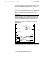
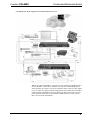
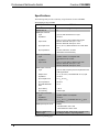
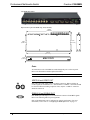
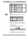
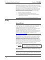
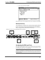
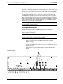
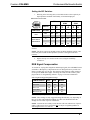
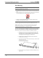
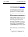
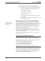
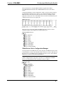
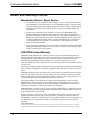
Crestron C2N-MMS Professional Multimedia Switch Operations Guide This document was prepared and written by the Technical Documentation department at: Crestron Electronics, Inc. 15 Volvo Drive Rockleigh, NJ 07647 1-888-CRESTRON All brand names, product names and trademarks are the property of their respective owners. ©2005 Crestron Electronics, Inc. Crestron C2N-MMS Professional Multimedia Switch Contents Professional Multimedia Switch: C2N-MMS 1 Introduction ............................................................................................................................... 1 Features and Functions ................................................................................................ 1 Specifications .............................................................................................................. 4 Physical Description.................................................................................................... 5 Industry Compliance ................................................................................................... 7 Setup .......................................................................................................................................... 8 Network Wiring........................................................................................................... 8 Crestron Toolbox......................................................................................................... 9 Identity Code ............................................................................................................... 9 Hardware Hookup ..................................................................................................... 11 Configuring the RGB Input Ports.............................................................................. 11 RGB Signal Compensation........................................................................................ 13 Rack Mounting .......................................................................................................... 14 Programming Software ............................................................................................................ 15 Earliest Version Software Requirements for the PC ................................................. 15 Programming with the Crestron SystemBuilder........................................................ 16 Programming with SIMPL Windows ........................................................................ 16 Programming with VisionTools Pro-e....................................................................... 18 Uploading and Upgrading........................................................................................................ 19 Establishing Communications ................................................................................... 19 Troubleshooting Communications ............................................................................ 21 Uploading a SIMPL Windows Program.................................................................... 21 Firmware Upgrade..................................................................................................... 23 Problem Solving ...................................................................................................................... 25 Troubleshooting......................................................................................................... 25 Further Inquiries ........................................................................................................ 25 Future Updates .......................................................................................................... 25 Return and Warranty Policies .................................................................................................. 26 Merchandise Returns / Repair Service ...................................................................... 26 CRESTRON Limited Warranty................................................................................. 26 Operations Guide – DOC. 6374 Contents • i Crestron C2N-MMS Professional Multimedia Switch Professional Multimedia Switch: C2N-MMS Introduction Features and Functions The Crestron® Professional Multimedia Switch C2N-MMS is a high performance multimedia switch that can switch four RGB sources to two RGB devices and three video sources to two video devices. With the optional C2N-MMS-SC scan converter card, the RGB sources can also be switched to the video devices. The C2N-MMS features three Y/C (S-video)/composite inputs, four RGB inputs, two Y/C (S-video)/composite outputs, and two RGB outputs. C2N-MMS Functional Summary • • • • • • • • * Four RGB input channels with selectable sync impedance* and AutoDetect Two RGB output channels with user-selectable frequency and level compensation for longer cable runs Three video input channels with Auto-Detect supporting composite and Y/C (S-video) formats Two video output channels supporting composite and Y/C (S-video) formats Supports NTSC and PAL signal types Transient blanking on RGB input signals to avoid visible transients when switching between RGB sources 400 MHz bandwidth for RGB signals, 100 MHz bandwidth for video signals Optional scan converter card C2N-MMS-SC allows RGB signals to be switched to video output devices Selectable sync impedance is only available on C2N-MMS devices with the part number 6003312 on the manufacturing label located on the bottom of the unit. Units labeled with 6001581 do not have this feature. The C2N-MMS can drive RGB cable runs over 100 feet with user-selectable frequency and level compensation on the RGB outputs. The RGB inputs feature selectable impedance on the sync input that may alleviate problems experienced with Operations Guide – DOC. 6374 Professional Multimedia Switch: C2N-MMS • 1 Professional Multimedia Switch Crestron C2N-MMS coax cables of longer lengths (50 to 100 feet). The C2N-MMS automatically detects the presence of video and RGB signals by monitoring activity on the luminance (COMP/Y) connection of each video input and the horizontal sync line of each RGB input. For laptops that require the presence of a monitor to enable its video output, the C2N-MMS has a selectable feature (DDC) that simulates the presence of a generic high-resolution monitor so RGB sources (such as a laptop computer) will transmit a signal even when a RGB device is not connected to the C2N-MMS output. NOTE: Selectable sync impedance and the DDC feature are only available on C2N-MMS devices with the part number 6003312 on the manufacturing label located on the bottom of the unit. Units labeled with part number 6001581 do not have this feature. RGB signal switching features transient blanking to avoid visible transients when switching between RGB sources operating at different sync frequencies. Transient blanking disables the output signal before the sync is switched to another source. Transient-free switching between RGB sources is completed in less than 1/10 of a second. The following diagram illustrates the functional capabilities of the C2N-MMS. Functional Diagram Video 1 IN Video 1 OUT 3 X 2 SWITCH Video 2 IN 100MHz Video 2 OUT Video 3 IN RGB 1 IN RGB 1 OUT DIP Switches RGB 2 IN DIP Switches RGB 3 IN DIP Switches RGB 4 IN DIP Switches 4 X 2 SWITCH Cable Compensation RGB 2 OUT 400MHz Cable Compensation NOTE: DIP switches for selecting input impedance and the DDC feature are only available on C2N-MMS devices with the part number 6003312 on the manufacturing label located on the bottom of the unit. Units labeled with part number 6001581 do not have this feature. Refer to “Configuring the RGB Input Ports” on page 11 for more information. When used in conjunction with a Crestron MP2E Multimedia Processor or other 2-Series Control Processors, the C2N-MMS provides a variety of switching solutions. The following diagram illustrates a sample application using the C2N-MMS with a Crestron MP2E Multimedia Processor. 2 • Professional Multimedia Switch: C2N-MMS Operations Guide – DOC. 6374 Crestron C2N-MMS Professional Multimedia Switch C2N-MMS in Basic Room Configuration with MP2E Multimedia Processor With the optional C2N-MMS-SC scan converter card, signals from the RGB sources can be switched to a video device. With the scan converter installed, RGB sources with resolutions up to 2048 x 1536 can be switched to either of the two video outputs in Y/C (S-video) or composite formats using National Television System Committee (NTSC) or Phase Alternating Line (PAL) signal types. Refer to the Scan Converter Card Operations Guide (Doc. 6138) which is available from the Crestron website (http://www.crestron.com/manuals). Operations Guide – DOC. 6374 Professional Multimedia Switch: C2N-MMS • 3 Professional Multimedia Switch Crestron C2N-MMS Specifications The following table provides a summary of specifications for the C2N-MMS. Specifications for the C2N-MMS SPECIFICATION ® DETAILS Cresnet Power Usage 6 Watts (0.25 Amp @ 24 VDC) Default NET ID 11 RGB Input Channels Type (4) D-15 with Auto-Detect on H sync Impedance 75 ohms Input Levels 0.3Vpp to 1.5 Vpp with no offset at unity gain Max DC offset with min input: ±1.0 V Max DC offset with max input: ±0.5 V Sync Input Level 2.0 Vpp to 5 Vpp offset tolerant to ±2.5 VDC offset max. Sync Impedance 1k ohms, 500 ohms, 75 ohms (Selectable via DIP switches) Video Input Channels Type Impedance Input Levels (3) BNC S-Video or Composite with Auto-Detect on the Y input 75 0.3Vpp to 1.5Vpp with no offset at unity gain Max DC offset with min input: ±1.0V Max DC offset with max input: ±0.5V RGB Output Channels Type (2) D-15 with Frequency/Level Compensation and 3 dB Signal Boost Output Level 0.7 Vpp to 0.75 Vpp terminated with 0.7 Vpp input Impedance 75 ohms Sync Output Level 4.0 Vpp to 5.0 Vpp Sync Impedance 33 ohms Sync Max Rise/Fall Time 3.5 ns Sync Latency < 30 ns Sync Polarity Follows input Video Output Channels Type (2) BNC S-Video or Composite Impedance 75 ohms Output Level 1.0 Vpp to 1.1 Vpp terminated with 1.0 Vpp input (composite) RGB Input/Output Format RGBHV Min Resolution: 460 x 400 Max Resolution: 2048 x 1536 Maximum RGB Output Cable Length Tested to 100 feet. Cable length in excess of 100 feet may be subject to signal degradation. (continued on following page) 4 • Professional Multimedia Switch: C2N-MMS Operations Guide – DOC. 6374 Crestron C2N-MMS Professional Multimedia Switch Specifications for the C2N-MMS (continued) SPECIFICATION DETAILS Supported Video Signal Formats National Television System Committee (NTSC) & Phase Alternating Line (PAL) Bandwidth RGB: 400 MHz (-3 dB) at unity gain Video: 100 MHz (-3 dB) at unity gain Firmware C2N-MMS.v2.14.upg or later Control System Update Files1,2 2-Series Control System Version C2-V3015.CUZ or later MP2/MP2E Version MP2-V3016.CUZ or later Operating Temperature and Humidity 41º to 104º F (5º to 40º C), Dimensions and Weight Height: 1.70 in (4.32 cm) 10 to 90% Relative Humidity (non-condensing) Width: 17.03 in (43.26 cm) without mounting ears Depth: 7.15 in (18.16 cm) Weight: 3.4 lbs (1.5 kg) 1. 2. The latest software versions can be obtained from the Crestron website. Refer to the NOTE following these footnotes. Crestron 2-Series control systems include the AV2 and PRO2. Consult the latest Crestron Product Catalog for a complete list of 2-Series control systems. NOTE: Crestron software and any files on the website are for Authorized Crestron dealers and Crestron Authorized Independent Programmers (CAIP) only. New users may be required to register to obtain access to certain areas of the site (including the FTP site). Physical Description The front panel of the C2N-MMS contains a green (PWR) and yellow (NET) LED that illuminate when power is on and during network communications respectively. The rear panel of the C2N-MMS contains ten BNC connectors that compose the three chrominance/luminance (Y/C) video inputs and two Y/C video outputs. The C2N-MMS also contains six HD15 connectors that compose the four RGB inputs and two RGB outputs. DIP switches located inside the device are used to configure the RGB inputs. For more information on the DIP switches, refer to “Configuring the RGB Input Ports” on page 11. Two four-position terminal block connectors provide connectivity to the Cresnet network. A pushbutton with an indicating red LED marked “SETUP” is for Touch-Settable ID operation. NOTE: DIP switches for selecting sync input impedance and the DDC feature are only available on C2N-MMS devices with the part number 6003312 on the manufacturing label located on the bottom of the unit. Units labeled with part number 6001581 do not have this feature. The C2N-MMS can be placed in a rack (with included mounting ears) or on a table with the supplied rubber feet. Refer to “Rack Mounting” on page 14 for more information. Operations Guide – DOC. 6374 Professional Multimedia Switch: C2N-MMS • 5 Professional Multimedia Switch Crestron C2N-MMS C2N-MMS (Rear Panel) Physical Views of the C2N-MMS (Top, Front, and Side) 16.92 in (42.98 cm) 7.15 in (18.17 cm) 6.44 in (16.35 cm) 17.03 in (43.25 cm) 1.70 in (4.32 cm) Ports All connections to the C2N-MMS are made through the ports on the rear panel. Refer to the illustrations and descriptions that follow. NOTE: Interface connectors for the NET ports are provided with the C2N-MMS. VIDEO IN and VIDEO OUT Each video input and output features two BNC connectors. When switching an S-video signal, the chrominance “C” and Luminance “COMP/Y” connectors should be connected. When switching composite video, only the “COMP/Y” connector should be connected. RGBHV IN and RGBHV OUT Each RGB input and output uses a standard HD15 connector for RGBHV signals. Refer to the following table for pin assignments. Each of the RGB inputs can be configured to optimize performance. For more information, refer to refer to “Configuring the RGB Input Ports” on page 11. 6 • Professional Multimedia Switch: C2N-MMS Operations Guide – DOC. 6374 Crestron C2N-MMS Professional Multimedia Switch RGBHV Pinouts PIN FUNCTION PIN FUNCTION 1 Red Video 9 No Connect 2 Green Video 10 Ground 3 Blue Video 11 No Connect 4 Reserved 12 Monitor Sense (input) / No Connect (output) 5 Ground 13 Horizontal Sync 6 Red Ground 14 Vertical Sync 7 Green Ground 15 Monitor Sense Clock (input) / No Connect (output) 8 Blue Ground NET Two 4-position terminal block connectors are used to connect the C2N-MMS to the Cresnet system. Data and power for the C2N-MMS are provided via either connection. Refer to “Network Wiring” on page 8. NET Pinouts PIN # DESIGNATION DESCRIPTION 1 24 Power 2 Y Data 3 Z Data 4 G Ground SETUP LED and Pushbutton The C2N-MMS is Touch Settable (TSID) ready. The SETUP pushbutton and its associated LED are located on the rear panel and are used for setting up the unit’s network ID during the initial configuration of a Cresnet system or when the device is being added/replaced. Refer to “Identity Code” on page 9 for detailed information. Industry Compliance As of the date of manufacture, the C2N-MMS has been tested and found to comply with specifications for CE marking and standards per EMC and Radiocommunications Compliance Labelling. NOTE: This device complies with part 15 of the FCC rules. Operation is subject to the following two conditions: (1) this device may not cause harmful interference, and (2) this device must accept any interference received, including interference that may cause undesired operation. This equipment has been tested and found to comply with the limits for a Class B digital device, pursuant to part 15 of the FCC Rules. These limits are designed to provide reasonable protection against harmful interference in a residential Operations Guide – DOC. 6374 Professional Multimedia Switch: C2N-MMS • 7 Professional Multimedia Switch Crestron C2N-MMS installation. This equipment generates, uses and can radiate radio frequency energy and, if not installed and used in accordance with the instructions, may cause harmful interference to radio communications. However, there is no guarantee that interference will not occur in a particular installation. If this equipment does cause harmful interference to radio or television reception, which can be determined by turning the equipment off and on, the user is encouraged to try to correct the interference by one or more of the following measures: Reorient or relocate the receiving antenna. Increase the separation between the equipment and receiver. Connect the equipment into an outlet on a circuit different from that to which the receiver is connected. Consult the dealer or an experienced radio/TV technician for help. Setup Network Wiring CAUTION: In order to ensure optimum performance over the full range of your installation topology, Crestron Certified Wire, and only Crestron Certified Wire, may be used. Failure to do so may incur additional charges if support is required to identify performance deficiencies as a result of using improper wire. CAUTION: Use only Crestron power supplies for Crestron equipment. Failure to do so could cause equipment damage or void the Crestron warranty. CAUTION: Provide sufficient power to the system. Insufficient power can lead to unpredictable results or damage to the equipment. Please use the Crestron Power Calculator to help calculate how much power is needed for the system (http://www.crestron.com/calculators). When calculating the length of wire for a particular Cresnet run, the wire gauge and the Cresnet power usage of each network unit to be connected must be taken into consideration. Use Crestron Certified Wire only. If Cresnet units are to be daisychained on the run, the Cresnet power usage of each network unit to be daisychained must be added together to determine the Cresnet power usage of the entire chain. If the unit is a home-run from a Crestron system power supply network port, the Cresnet power usage of that unit is the Cresnet power usage of the entire run. The wire gauge and the Cresnet power usage of the run should be used in the following equation to calculate the cable length value on the equation’s left side. Cable Length Equation 40,000 L< RxP Where: L = Length of run (or chain) in feet. 2 R = 6 Ohms (Crestron Certified Wire: 18 AWG (0.75 MM )) P = Cresnet power usage of entire run (or chain). Make sure the cable length value is less than the value calculated on the right side of the equation. For example, a Cresnet run drawing 20 watts should not have a length of run more than 333 feet. NOTE: All Crestron certified Cresnet wiring must consist of two twisted pairs. One twisted pair is the +24V conductor and the GND conductor, and the other twisted pair is the Y conductor and the Z conductor. 8 • Professional Multimedia Switch: C2N-MMS Operations Guide – DOC. 6374 Crestron C2N-MMS Professional Multimedia Switch NOTE: When daisy-chaining Cresnet units, strip the ends of the wires carefully to avoid nicking the conductors. Twist together the ends of the wires that share a pin on the network connector, and tin the twisted connection. Apply solder only to the ends of the twisted wires. Avoid tinning too far up the wires or the end becomes brittle. Insert the tinned connection into the Cresnet connector and tighten the retaining screw. Repeat the procedure for the other three conductors. NOTE: For larger networks (i.e., greater than 28 network devices), it may become necessary to add a Cresnet Hub/Repeater (CNXHUB) to maintain signal quality throughout the network. Also, for networks with lengthy cable runs, it may be necessary to add a Hub/Repeater after only 20 devices. Crestron Toolbox NOTE: The minimum version of Crestron Toolbox required to operate with the C2N-MMS is version 1.0.06 or later. The Crestron Toolbox (a replacement for Crestron Viewport, you may continue to use Viewport version 3.109 or later if desired) is a broad-based software package that accomplishes multiple system tasks, primarily using an RS-232 or TCP/IP connection between a PC and one or more Crestron control systems. You can use the Crestron Toolbox to: • Observe system processes. • Upload operating systems and firmware. • Upload programs and touchpanel projects. • Set or change device Network IDs. • Change serial numbers. • Run scripts to automate tasks. • Perform system diagnostics, and much more. The Crestron Toolbox allows you to perform these functions using simple graphical views and click and drag methods. Identity Code Every network device and user interface within the Cresnet network requires a unique identity code (Net ID). These codes are two-digit hexadecimal numbers from 03 to FE. The Net ID of each unit must match an ID code specified in the SIMPL Windows program. Refer to “Setting the Net ID in Device Settings” on page 18 for details of the SIMPL Windows procedure. The Net ID of the C2N-MMS has been factory set to 11. The Net IDs of multiple C2N-MMS devices in the same system must be unique. Net IDs are changed from a personal computer (PC) via the Crestron Toolbox. NOTE: For detailed information on establishing communication between the PC, control system, and the C2N-MMS, refer to “Establishing Communications” on page 19. If communication cannot be established, refer to the “Troubleshooting Communications” section in the latest version of the 2-Series Control System Reference Guide (Doc. 6256), which is available from the Crestron website. Operations Guide – DOC. 6374 Professional Multimedia Switch: C2N-MMS • 9 Professional Multimedia Switch Crestron C2N-MMS The Crestron Toolbox provides several methods to easily set or change device Net IDs for any device on the network. The following method permits you to change the Net ID of any device in the network through the “Network Device Tree” window. NOTE: This method prevents you from selecting an existing Net ID that is assigned to a device that is not equipped with TSID. This method permits you to manually set the Net ID for any device in the network, set any known Net IDs that may require changing, and may also be used for nonTSID equipment. This method will not permit you to choose an ID already in use by another device that is not equipped with TSID. A warning message will appear if you attempt to use an ID that is already in use by a device that is equipped with TSID. Duplicate Net ID Warning Message This method does not change the Net ID as assigned in SIMPL Windows. For information on setting the Net ID in SIMPL Windows, refer to “Setting the Net ID in Device Settings” on page 18. NOTE: You may also use SystemBuilder™ to perform Network ID setup. Refer to the respective help file for more information. 1. Ensure that all network devices are connected to the control system. 2. Open Crestron Toolbox and establish communications (refer to Establishing Communications on page 19). 3. Select the Network Device Tree Device Tree. 4. Expand the device tree until the Net ID that is to be changed is visible. Right-click on the Net ID, and when the sub-menu appears, select Change Network ID. icon, or select Tools | Network “Network Device Tree” – Sub-Menu 10 • Professional Multimedia Switch: C2N-MMS Operations Guide – DOC. 6374 Crestron C2N-MMS Professional Multimedia Switch 5. Select a new Net ID and press Enter. Enter New Net ID Repeat this procedure for each additional network device requiring a Net ID change. Hardware Hookup The C2N-MMS can be mounted in a rack or stacked with other equipment. Make the necessary connections as called out in the illustration that follows this paragraph. Refer to “Network Wiring” on page 8 before attaching the 4-position terminal block connector. Apply power after all connections have been made. Hardware Connections for the C2N-MMS (Back of the Unit is Shown) VIDEO IN COMP Y C COMP Y C G R O U N D RGBHV INPUTS: AUTODETECTION ON H SYNC VIDEO INPUTS: COMPOSITE OR S-VIDEO VIDEO OUT COMP Y C COMP Y C SETUP COMP Y NET C RGBHV IN 1 2 3 C R E S T R O N E L E C T R O N IC S I N C . R O C K L E I G H , N . J . 0 7 6 4 7 U S A 1 CRESNET: TO ANY CRESNET NETWORK DEVICE SETUP: FOR TOUCHSETTABLE CRESNET ID 2 1 2 24 Y Z G 3 4 1 24 Y Z G RGBHV OUT 2 RGBHV OUTPUTS: FREQUENCY AND LEVEL COMPENSATION VIDEO OUTPUTS: COMPOSITE OR S-VIDEO Configuring the RGB Input Ports Each of the four RGB input ports feature a set of six DIP switches located inside the C2N-MMS. These switches are used to configure the sync input impedance of each port and enable the DDC feature of each RGB input. NOTE: DIP switches for selecting input impedance and the DDC feature are only available on C2N-MMS devices with the part number 6003312 on the manufacturing label located on the bottom of the unit. Units labeled with part number 6001581 do not have this feature. Operations Guide – DOC. 6374 Professional Multimedia Switch: C2N-MMS • 11 Professional Multimedia Switch Crestron C2N-MMS The sync input impedance can be set to either 1k, 500, or 75 ohms. The setting from the factory is 1k ohms and should work with most RGB sources. If the signal quality is poor, lowering the input impedance to match the impedance of coax cable may alleviate sync signal problems that are associated with RGB cables greater than the typical VESA standard (typically six feet). For laptops that require the presence of a monitor to enable its video output, the C2N-MMS has a selectable feature (DDC) that simulates the presence of a generic high-resolution monitor so RGB sources (such as a laptop computer) will transmit a signal even when a RGB device is not connected to the C2N-MMS output. Changing a DIP switch setting can enable or disable this feature. The C2N-MMS is shipped from the factory with the DDC feature disabled. NOTE: The sync input impedance and DDC feature should be set prior to placing the C2N-MMS in an equipment rack. Finding the DIP Switches The DIP switches that configure the RGB input ports are located inside the C2N-MMS. The only tools required are a #2 Phillips screwdriver and a grounding strap (or grounded workstation). CAUTION: The C2N-MMS contains ESD-sensitive devices. Perform the following procedure while wearing a grounding strap that is properly grounded or on a grounded workstation to avoid damaging the C2N-MMS. 1. Make all connections to the C2N-MMS as described in “Hardware Hookup” on page 11. 2. Open the C2N-MMS by removing the 16 screws (located on the sides and top of the C2N-MMS) securing the top cover. Use a #2 Phillips screwdriver to remove the screws. 3. Remove the lid to expose the DIP switches as shown in the following diagram. DIP Switch Location DIP SWITCHES 12 • Professional Multimedia Switch: C2N-MMS Operations Guide – DOC. 6374 Crestron C2N-MMS Professional Multimedia Switch Setting the DIP Switches 1. Referring to the following table, set the DIP switches to the required sync input impedance and DDC functionality of each RGB input port. DIP Switch Function Chart DDC DDC VERTICAL SYNC 1 2 3 4 5 6 OFF OFF OFF X X X X ON ON ON X X X X 1K X X OFF OFF OFF OFF 500 X X ON OFF ON OFF 75 X X ON ON ON ON SWITCH FUNCTION HORIZONTAL SYNC SETTING SYNC INPUT IMPEDANCE NOTE: The function table is also located on the C2N-MMS adjacent to the DIP switches. NOTE: The factory setting for the DIP switches are DDC disabled (switches 1 & 2 in the OFF position) and 1k ohm impedance (switches 3 through 6 in the OFF position). 2. Replace the top cover and secure the screws using the #2 Phillips screwdriver. RGB Signal Compensation To account for varying cable lengths for RGB output signals, the C2N-MMS features switchable 3 dB frequency compensation and 1.25 dB signal boost to provide clear images on cable runs over 100 feet. The following table illustrates which settings to use for specific RGB cable lengths. All settings are made from the control system program. Refer to “Programming Software” on page 15 for more information. Cable Length and Suggested EQ/Boost Settings CABLE LENGTH EQ1 EQ2 BOOST 0 to 25 ft Off Off Off 25 to 50 ft On Off Off 50 to 75 ft Off On Off 75 to 100 ft On On Off More than 100 On On On NOTE: The sync output is not affected by peak and boost settings. NOTE: These settings are only suggested settings. Results may vary depending on the type of cable and installation methods used. The user should determine the settings for best results in specific installations. NOTE: Crestron has successfully tested 100-foot cable runs without loss of picture quality. Cable runs in excess of 100 feet may be subject to signal degradation as cable length increases over 100 feet. Operations Guide – DOC. 6374 Professional Multimedia Switch: C2N-MMS • 13 Professional Multimedia Switch Crestron C2N-MMS Rack Mounting WARNING: To prevent bodily injury when mounting or servicing this unit in a rack, take special precautions to ensure that the system remains stable. The following guidelines are provided to ensure your safety: • • • The unit should be mounted at the bottom of the rack if it is the only unit in the rack. When mounting this unit in a partially filled rack, load the rack from the bottom to the top with the heaviest component at the bottom of the rack. If the rack is provided with stabilizing devices, install the stabilizers before mounting or servicing the unit in the rack. NOTE: If rack mounting is not required, rubber feet are provided for shelf placement or stacking. Apply the feet near the corner edges on the underside of the unit. NOTE: Reliable earthing of rack-mounted equipment should be maintained. Particular attention should be given to supply connections other than direct connections to the branch circuit. (e.g., use of power strips). Two “ears” are provided with the C2N-MMS so that the unit can be rack mounted. These ears must be installed prior to mounting. Complete the following procedure to attach the ears to the unit. The only tool required is a #2 Phillips screwdriver. 1. There are 12 screws (#6-32 x 0.375" LG) that secure the sides of the C2N-MMS top cover. Using a #2 Phillips screwdriver, remove the three screws closest to the front panel from one side of the unit. Refer to the diagram on the following page for a detailed view. 2. Position a rack ear so that its mounting holes align with the holes vacated by the screws in step 1. 3. Secure the ear to the unit with three screws from step 1, as shown in the illustration after this step. Ear Attachment for Rack Mounting 4. Repeat procedure (steps 1 through 3) to attach the remaining ear to the opposite side. 14 • Professional Multimedia Switch: C2N-MMS Operations Guide – DOC. 6374 Crestron C2N-MMS Professional Multimedia Switch Programming Software Have a question or comment about Crestron software? Answers to frequently asked questions (FAQs) can be viewed in the Online Help section of the Crestron website. To post a question or view questions you have submitted to Crestron’s True Blue Support, log in at http://support.crestron.com. First-time users will need to establish a user account. Setup is easy thanks to Crestron’s Windows-based programming software. Crestron’s SystemBuilder software creates a complete project, with no special programming required. While traditional programming tools can still be used to program a system, SystemBuilder can be used to easily complete all necessary programming for a base system including all touchpanel screens and the control system program. The program output of SystemBuilder is a SIMPL Windows program with much of the functionality encapsulated in macros and templates. Once SystemBuilder creates the project, the system interfaces and program logic can be customized in SystemBuilder or can be easily modified with Crestron development tools (i.e., SIMPL Windows and Crestron VisionTools® Pro-e (VT Pro-e) software packages). NOTE: Modifications to the program that are made outside of SystemBuilder (for example, in VT Pro-e or SIMPL Windows) are not preserved when you reenter SystemBuilder. SystemBuilder comes with templates for all supported interfaces. If a user wishes to create a touchpanel project using templates with a different look-and-feel, this can be accomplished by making a custom template. This custom template can then be used by SystemBuilder to create the final project files to be loaded into the panels. Alternatively, VT Pro-e can be used to tweak projects created with the SystemBuilder or develop original touchpanel screen designs. Digital, analog and serial join numbers are a common thread between VT Pro-e and SIMPL Windows. These numbers define how the objects on a touchpanel page of a VT Pro-e project interface to the outside world, specifically the Cresnet system as defined in the SIMPL Windows program. There are digital join numbers that carry out some predetermined function (a logical high or low); analog join numbers for displaying incremental values, sliders, gauges and bar graphs; and serial join numbers that allow for the display of variable text and transmission/reception of serial commands from other manufacturers. Unjoined objects are not interfaced with the system and thus cannot initiate any logic functions (although they can perform page flips). Earliest Version Software Requirements for the PC NOTE: Crestron recommends that you use the latest software to take advantage of the most recently released features. The latest software is available from the Crestron website. The following are the minimum recommended software versions for the PC: Operations Guide – DOC. 6374 • SIMPL Windows version 2.03.17 or later. Requires SIMPL+ Cross Compiler version 1.1 or later. • Crestron Toolbox 1.01.06 or later Professional Multimedia Switch: C2N-MMS • 15 Professional Multimedia Switch • Crestron C2N-MMS (Optional) SystemBuilder version 2.0 or later with SystemBuilder Templates version 2.0.1or later. Requires the following software versions: o SIMPL Windows version 2.06.20 or later with library update file 345 or later. Requires SIMPL+ Cross Compiler version 1.1. o Crestron database 17.2.2 or later o Vision Tools Pro-e 3.3.4.0 or later o Crestron Toolbox 1.01.06 or later o Engraver 2.4.1.2 or later o Microsoft DCOM '98 if running under Win 95 or 98 (not needed for NT or 2000) o Microsoft Data Access Components if running under Win 95 or 98 (not needed for NT or 2000) Programming with the Crestron SystemBuilder The easiest method of programming, but does not offer as much flexibility as SIMPL Windows. Crestron SystemBuilder offers automatic programming for such residential and commercial applications as audio distribution, home theater, video conferencing, and lighting. The interface of this tool guides you through a few basic steps for designating rooms and specifying the control system, touchpanels, devices, and functionality. Crestron SystemBuilder then programs the system, including all touchpanel projects and control system logic. Crestron SystemBuilder is fully integrated with Crestron's suite of software development tools, including SIMPL Windows, VT Pro-e, and the Crestron Database. Crestron SystemBuilder accesses these tools behind the scenes, enabling you to easily create robust systems. For additional details, download SystemBuilder from the Crestron website and examine the extensive help file. Programming with SIMPL Windows NOTE: The following assumes that the reader has knowledge of SIMPL Windows. If not, refer to the extensive help information provided with the software. NOTE: The following are acceptable file extensions for programs that include a C2N-MMS, developed for specific control system types: .smw: projectname.smw (SIMPL Windows source file) .spz: projectname.spz (compiled file for 2-series) .usp: projectname.usp (source code module for SIMPL+) .umc: projectname.umc (user macro for SIMPL) NOTE: In the following description, the MP2E multimedia processor is used. SIMPL Windows is Crestron's software for programming Crestron control systems. It provides a well-designed graphical environment with a number of workspaces (i.e., windows) in which a programmer can select, configure, program, test, and monitor a Crestron control system. SIMPL Windows offers drag and drop functionality in a familiar Windows® environment. 16 • Professional Multimedia Switch: C2N-MMS Operations Guide – DOC. 6374 Crestron C2N-MMS Professional Multimedia Switch This section describes a sample SIMPL Windows program that includes a C2N-MMS Multimedia Switch with an MP2E Media Processor as the control system. Configuration Manager is where programmers “build” a Crestron control system by selecting hardware from the Device Library. In Configuration Manager, drag the MP2E from the Control Systems folder of the Device Library and drop it in the upper pane of the System Views. The MP2E with its associated communication ports is displayed in the System Views upper pane. MP2E System View The System Views lower pane displays the MP2E system tree. This tree can be expanded to display and configure the communications ports. Expanded MP2E System Tree C2Net-Device Slot in Configuration Manager To incorporate the C2N-MMS into the system, drag the C2N-MMS from the Cresnet Control Modules | Cresnet Video Modules folder of the Device Library and drop it in the System Views. The MP2E system tree displays the device in slot 1 with a default NET ID of 11 as shown in the following illustration. NOTE: The first C2N-MMS in a system is preset with a NET ID of 11, when its symbol is dragged into the upper pane of System Views. Additional C2N-MMS devices are assigned different NET ID numbers as they are added. C2Net Device, Slot 1 Operations Guide – DOC. 6374 Professional Multimedia Switch: C2N-MMS • 17 Professional Multimedia Switch Crestron C2N-MMS Setting the Net ID in Device Settings Double-click the C2N-MMS icon to open the “Device Settings” window. This window displays the C2N-MMS device information. If necessary, select the Net ID tab to change the Net ID, as shown in the following figure. “Device Settings” Window for the C2N-MMS NOTE: SIMPL Windows automatically changes Net ID values of a device added to a program if a duplicate device or a device with the same default Net ID already exists in the program. Always ensure that the hardware and software settings of the Net ID match. For Net ID hardware settings details, refer to “Identity Code” on page 9. C2N-MMS Symbol in Programming Manager Programming Manager is where programmers "program" a Crestron control system by assigning signals to symbols. The symbol can be viewed by double clicking on the icon or dragging it into Detail View. A description for each signal in the symbol is described in the SIMPL Windows help file (F1). Example Program An example program for the C2N-MMS is available from the “Example Program” section of the Crestron website (http://www.crestron.com/exampleprograms). Search for C2N-MMS.ZIP. Programming with VisionTools Pro-e Touchpanel screens should be created in VT Pro-e to allow switching of source signals to desired outputs as well as selection of frequency compensation and signal boost. There are no special programming requirements to use the functions of the C2N-MMS in a room-control system. 18 • Professional Multimedia Switch: C2N-MMS Operations Guide – DOC. 6374 Crestron C2N-MMS Professional Multimedia Switch Uploading and Upgrading NOTE: Crestron recommends using the latest programming software and that each device contains the latest firmware to take advantage of the most recently released features. Please check the Crestron website (http://www.crestron.com/updates) for the latest versions of software and firmware. New users are required to register to obtain access to this site. Assuming a PC is properly connected to the entire system, Crestron programming software allows the programmer to upload programs to the control system after their development and firmware upgrades to network devices. However, there are times when the files for the program are compiled and not uploaded. Instead, compiled files may be distributed from programmers to installers, from Crestron to dealers, etc. Even firmware upgrades are available from the Crestron website as new features are developed after product releases. In those instances, one has the option to upload via the programming software or to upload and upgrade via the Crestron Toolbox. NOTE: Refer to the “Crestron Toolbox” on page 9 for important information regarding compatible versions of Crestron Toolbox and Viewport. The following sections define how one would upload a SIMPL Windows program to the control system or upgrade the firmware of the C2N-MMS. However, before attempting to upload or upgrade, it is necessary to establish communications between the PC and the C2N-MMS. Establishing Communications The procedure in this section provides details for RS-232 communication between a PC and the C2N-MMS via the control system. This method can be used to communicate with the control system directly and with a C2N-MMS via the control system’s Cresnet connection. If TCP/IP communication is preferred, consult the latest version of the Crestron e-Control Reference Guide (Doc. 6052) or the respective Operations Guide for the control system. These documents are available from the Crestron website. Refer to the following figure for a typical connection diagram when connecting to a C2N-MMS via a control system. Indirect Serial Communications Setup Connections Cresnet Control System Operations Guide – DOC. 6374 RS-232 Serial Cable 1. Ensure that all devices are connected to the control system and the control system is connected via serial cable to the PC. 2. Open Crestron Toolbox and click Tools | Manage Address Book to display a list of available devices. Select Serial on COM1 as the connection type. Serial on COM1 is an entry in the DefaultAddressBook that is included with Crestron Toolbox. Professional Multimedia Switch: C2N-MMS • 19 Professional Multimedia Switch Crestron C2N-MMS The PC communication settings specified here should match the protocol that the control processor expects. The usual settings are as follows: • Port = COM 1 through COM 8. Select the correct COM port on the PC. • Baud rate = Auto-detect. • Parity = None. • Number of data bits = 8. • Number of stop bits = 1. • Hardware handshaking (RTS/CTS) enabled. • Software handshaking (XON/XOFF) not enabled. “Address Book” Window – Serial Setup 3. After setting the correct parameters, click OK to return to the Crestron Toolbox main window. 4. Click Tools | Network Device Tree, or click the network device tree icon to display the devices in the system. Select Serial on COM1 from the drop down list if it is not already selected. If communication is successful, the network devices that are connected to the control system are displayed. Network Device Tree 20 • Professional Multimedia Switch: C2N-MMS Operations Guide – DOC. 6374 Crestron C2N-MMS Professional Multimedia Switch To view a specific device, expand the network device tree by clicking +. Expand the network device tree till the device to be managed is selected. Right-click the desired Net ID to open the sub-menu. This menu provides a wide range of functions, including; change the Net ID, open text console, upload project, update firmware, etc. Network Device Tree Sub-Menu -Functions NOTE: Toolbox displays a customized list of functions depending on the type of device with which it is communicating. Troubleshooting Communications Use the following checklist if communication cannot be established with the control system. 1. Verify that the correct cables are used. Refer to the control systems Operations Guide for information about RS-232 cables. 2. With a serial connection, verify that the correct COM port on the PC has been selected. Some computers have more than one COM port; some may be internal (e.g., for a modem). Consult the manufacturer’s documentation for further information about the COM ports on your PC. 3. Remove and reapply power to the control system. 4. If communication still cannot be established, contact Crestron customer service. Uploading a SIMPL Windows Program The SIMPL Windows file can be uploaded to the control system using SIMPL Windows or via Crestron Toolbox. Upload via SIMPL Windows Operations Guide – DOC. 6374 1. Start SIMPL Windows. 2. Select File | Open to view the “Open” window, navigate to the SIMPL Window file (.smw), and click Open. 3. Select Project | Transfer Program. Professional Multimedia Switch: C2N-MMS • 21 Professional Multimedia Switch Crestron C2N-MMS Upload via Crestron Toolbox 1. Verify that the procedure for “Establishing Communications” that begins on page 19 has been performed to establish a connection between the PC and the control system. 2. Open Crestron Toolbox. 3. Select Tools | System Info. Crestron Toolbox – Tools | System Info 4. When the “System Info” window appears and you are connected to the control system, the Functions option becomes available from the menu bar. 5. Select Functions | SIMPL Program. The “SIMPL Program” window contains information about the currently loaded SIMPL program (if any), and permits you to stop, start, erase, retrieve, and upload a SIMPL program. This menu also permits you to upload to compact flash or internal flash. “SIMPL Program” Window 22 • Professional Multimedia Switch: C2N-MMS Operations Guide – DOC. 6374 Crestron C2N-MMS Professional Multimedia Switch 6. Click the button to browse for a new compiled (.spz) program. “Open” Window 7. Select a file and click Open. When the “SIMPL Program” window re-opens click Send. Firmware Upgrade To take advantage of all the device features, it is important that the unit contains the latest firmware available. Please check the Crestron website for the latest version of firmware. Not every product has a firmware upgrade, but as Crestron improves functions, adds new features, and extends the capabilities of its products, firmware upgrades are posted. To upgrade the firmware, complete the following steps. 1. Verify that the procedure for “Establishing Communications” that begins on page 19 has been performed. 2. Open Crestron Toolbox. 3. Open the Network Device Tree (the firmware upgrade function is also available in the SMW Program Tree window). 4. Right-click on the device and select Functions | Firmware. Network Device Tree Window – Right-Click Sub Menu 5. Operations Guide – DOC. 6374 The “Firmware” window displays the model and current firmware version. Click Upload New Firmware. Professional Multimedia Switch: C2N-MMS • 23 Professional Multimedia Switch Crestron C2N-MMS “Firmware” Window 6. When the following screen appears, browse to locate the firmware (.upg) file. Locate Firmware in the “Open” Window 7. Click Open and the file transfers to the unit. “File Transfer” Window 8. The “Firmware” window reopens indicating the new firmware version. Click Close after the firmware has been transferred. 24 • Professional Multimedia Switch: C2N-MMS Operations Guide – DOC. 6374 Crestron C2N-MMS Professional Multimedia Switch Problem Solving Troubleshooting The table after this paragraph provides corrective action for possible trouble situations. If further assistance is required, please contact a Crestron customer service representative. C2N-MMS Troubleshooting TROUBLE POSSIBLE CAUSE(S) CORRECTIVE ACTION PWR LED does not illuminate. C2N-MMS is not receiving power. Verify that cables plugged into the NET ports are secure. NET LED does not illuminate. Improper Net ID is set. Verify that C2N-MMS Net ID matches the Net ID in SIMPL Windows. Refer to “Identity Code” on page 9. Poor picture quality (RGB). Cables improperly connected. Verify that all cables are secure. Incorrect EQ and/or Boost compensation settings. Adjust EQ and/or Boost compensation settings. Display device not configured properly. Configure display device to match output frequency. Incorrect sync input impedance. Set DIP switches to lower sync input impedance. Cables improperly connected. Verify that all cables are secure. Poor picture quality (Video). Further Inquiries If you cannot locate specific information or have questions after reviewing this guide, please take advantage of Crestron's award winning customer service team by calling the Crestron corporate headquarters at 1-888-CRESTRON [1-888-273-7876]. For assistance in your local time zone, refer to the Crestron website (www.crestron.com) for a listing of Crestron worldwide offices. You can also log onto the online help section of the Crestron website to ask questions about Crestron products. First-time users will need to establish a user account to fully benefit from all available features. Future Updates As Crestron improves functions, adds new features, and extends the capabilities of the C2N-MMS, additional information may be made available as manual updates. These updates are solely electronic and serve as intermediary supplements prior to the release of a complete technical documentation revision. Check the Crestron website periodically for manual update availability and its relevance. Updates are identified as an “Addendum” in the Download column. Operations Guide – DOC. 6374 Professional Multimedia Switch: C2N-MMS • 25 Professional Multimedia Switch Crestron C2N-MMS Return and Warranty Policies Merchandise Returns / Repair Service 1. No merchandise may be returned for credit, exchange, or service without prior authorization from CRESTRON. To obtain warranty service for CRESTRON products, contact the factory and request an RMA (Return Merchandise Authorization) number. Enclose a note specifying the nature of the problem, name and phone number of contact person, RMA number, and return address. 2. Products may be returned for credit, exchange, or service with a CRESTRON Return Merchandise Authorization (RMA) number. Authorized returns must be shipped freight prepaid to CRESTRON, 6 Volvo Drive, Rockleigh, N.J., or its authorized subsidiaries, with RMA number clearly marked on the outside of all cartons. Shipments arriving freight collect or without an RMA number shall be subject to refusal. CRESTRON reserves the right in its sole and absolute discretion to charge a 15% restocking fee, plus shipping costs, on any products returned with an RMA. 3. Return freight charges following repair of items under warranty shall be paid by CRESTRON, shipping by standard ground carrier. In the event repairs are found to be non-warranty, return freight costs shall be paid by the purchaser. CRESTRON Limited Warranty CRESTRON ELECTRONICS, Inc. warrants its products to be free from manufacturing defects in materials and workmanship under normal use for a period of three (3) years from the date of purchase from CRESTRON, with the following exceptions: disk drives and any other moving or rotating mechanical parts, pan/tilt heads and power supplies are covered for a period of one (1) year; touchscreen display and overlay components are covered for 90 days; batteries and incandescent lamps are not covered. This warranty extends to products purchased directly from CRESTRON or an authorized CRESTRON dealer. Purchasers should inquire of the dealer regarding the nature and extent of the dealer's warranty, if any. CRESTRON shall not be liable to honor the terms of this warranty if the product has been used in any application other than that for which it was intended, or if it has been subjected to misuse, accidental damage, modification, or improper installation procedures. Furthermore, this warranty does not cover any product that has had the serial number altered, defaced, or removed. This warranty shall be the sole and exclusive remedy to the original purchaser. In no event shall CRESTRON be liable for incidental or consequential damages of any kind (property or economic damages inclusive) arising from the sale or use of this equipment. CRESTRON is not liable for any claim made by a third party or made by the purchaser for a third party. CRESTRON shall, at its option, repair or replace any product found defective, without charge for parts or labor. Repaired or replaced equipment and parts supplied under this warranty shall be covered only by the unexpired portion of the warranty. Except as expressly set forth in this warranty, CRESTRON makes no other warranties, expressed or implied, nor authorizes any other party to offer any warranty, including any implied warranties of merchantability or fitness for a particular purpose. Any implied warranties that may be imposed by law are limited to the terms of this limited warranty. This warranty statement supercedes all previous warranties. Trademark Information All brand names, product names, and trademarks are the sole property of their respective owners. Windows is a registered trademark of Microsoft Corporation. Windows95/98/Me/XP and WindowsNT/2000 are trademarks of Microsoft Corporation. 26 • Professional Multimedia Switch: C2N-MMS Operations Guide – DOC. 6374 Crestron C2N-MMS Professional Multimedia Switch This page intentionally left blank. Operations Guide – DOC. 6374 Professional Multimedia Switch: C2N-MMS • 27 Crestron Electronics, Inc. 15 Volvo Drive Rockleigh, NJ 07647 Tel: 888.CRESTRON Fax: 201.767.7576 www.crestron.com Operations Guide – DOC. 6374 (2012952) 10.05 Specifications subject to change without notice.