1
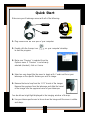
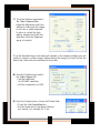
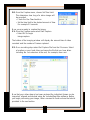
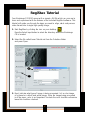
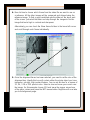
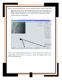
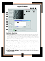
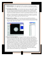
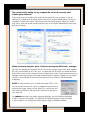
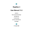
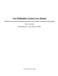
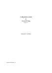
Table of Contents
Quick-Start and Tutorial
Imaging Basics
Registax User’s Guide
Troubleshooting
Quick Start
Make sure your NexImage comes with all of the following:
1.25” Barrel
USB Cable
Installation CD Rom
1. Plug camera into the USB port of your computer.
2. Double click the Amcap icon
to start the program.
on your computer’s desktop
3. Make sure “Preview” is selected from the
Options menu. If “Preview” is not already
selected (checked), click on it once.
4. Select an easy target like the moon to begin with. Center and focus your
telescope on the specific feature you wish to image.
5. Remove the barrel cap from the 1.25” barrel of the imager.
Remove the eyepiece from the telescope and slide the barrel
of the imager into the eyepiece barrel of your telescope.
You should see bright light displayed in the imaging window of Amcap.
6. Use your telescopes focuser to focus down the image until the moon is visible
and sharp.
1
7. From the Options menu select
the Video Capture Filter.
Adjust the Brightness and Gain
settings to make sure the image
is not over or under exposed.
In order to control the gain
setting, deselect (uncheck) the
Auto box under the Exposure
group of controls.
Once the desired image is focused and centered in the imaging window you are
ready to capture a video image. Before taking the image you must first set the
frame rate, time limit and resolution for the video.
8. From the Options menu select
the Video Capture Pin.
• Set the output size
to 640x480 resolution.
• Set the compression to I420
9. From the Capture menu, choose Set Frame Rate.
• Check the Use Frame Rate box
• Set the frame rate to the desired frames
per second. For example 30 f/sec.
2
10. From the Capture menu, choose Set Time Limit.
This determines how long of a video image will
be recorded.
• Check the Use Time Limit box
• Set the time limit to the desired amount of time.
For example 20 seconds.
Now you are ready to capture the image.
11. From the Capture menu select Start Capture
• Select OK to begin
image capture.
The bottom of the imaging window will display the amount time of video
recorded and the number of frames captured.
12. Once recording stops select Set Capture File from the File menu. Select
a location on your hard drive and name the file that you have taken
including the .avi extension at the end, for example, moon.avi.
Now that your video stream has been captured the individual frames can be
inspected, aligned and stacked using the included RegiStax software. Before
you begin processing your image, take a moment to read and use the tutorial
provided in the next section.
3
RegiStax Tutorial
Your NexImage CD ROM comes with a sample .AVI file which you can use to
learn and experiment with the features of the included RegiStax software. This
tutorial will guide you through the steps you need to align, stack and process
video frames into a single high quality image.
1. Start RegiStax by clicking the icon on your desktop.
Press the Select Input button to select the directory where the NexImage
CD is located.
2. Select the file called Lunar Tutorial.avi from the Celestron folder
and press Open.
2
3
3. Next, indicate what type of image is being processed. Is it a color image
of a planet or a black and white image. Since the image being processed
is of the moon, color is not important. Uncheck the color checkbox otherwise
leave this checkbox checked.
4
4. Now its time to choose which frame from the video file we want to use as
a reference. All the other images will be compared and aligned using the
reference-image. To find a good candidate use the slider on the lower part
of the screen. Just select the slider and step through the images to find an
image that looks high in contrast and sharpness.
Alternatively, you can check the Show frame list box in the lower left corner
and scroll through each frame individually.
4
5
5. Once the alignment frame has been selected, you need to set the size of the
alignment box. Ideally this box will contain either the whole object you have
imaged or a bright, high contrast feature. You can set this box to a square of
32, 64, 128 or 256 pixels in size. Select a size and move your cursor over
the image. For this example choose 128 and move the square around one
of the major craters and press the LEFT mouse button. RegiStax will now take
you to the alignment page.
5
Alignment Page
Here you are presented with many different controls that are discussed in detail
in the User's Guide. For this tutorial we will only discuss the most important
features. On this screen you should see two smaller windows that are on top of
the RegiStax Aligning window. One of them is the FFT-spectrum and the other is
called Registration properties. They are displayed using the two checkboxes
under the Options box. Both of these panels are useful when aligning images.
6. FFT-spectrum. This filter is used to estimate the alignment shift between the
reference frame and the rest of the frames in the sequence. Your initial image
should show a multi-colored square with a red circular area in the middle.
The red area in the middle represents where the program estimates the best
alignment. The FFT-spectrum is used to calculate the similarity between
images and estimates the best shift when aligning the images. Increase the
value of the Alignment filter to 12 and press the Recalc FFT button. Notice
that the red-area becomes smaller and the blue line in the Registration
properties graph changes position. Ideally only a small group of pixels
in the image should become red. This part of the image is used to register
(align) the images more accurately.
6
The next step is to weed out the blurred frames from your video sequence. The
Quality Filter Band shows the distribution of large and small details on each
frame. Images that show a high number of small features are a good indication
that the image is sharp.
6
7. Set the "start" quality filter to 10. This will position the two green lines so
that one is to the left of the blue line and one is to the right of the blue line.
Setting the band “width” filter to 9 defines the area under the Registration
Properties graph that is calculated as a proportion of the total area below
the graph. Ideally one of the vertical green lines should lie on the lower part
of the red curve while the other is positioned where the red-curve nearly
touches the bottom.
7
8
8. Press Align & Stack and Registax will automatically start the alignment
process. During this stage the program determines how much the object is
misaligned compared to the reference for every frame in the AVI file. Next
is the optimization process where only frames with good image quality are
optimized further. This is a more precise way of aligning the images. Once
all the frames are aligned and stacked you will automatically go to the
Processing Page.
7
Processing Page
The power of RegiStax sits in the usage of Wavelets. This is a special filtering
technique that is very good for enhancing details in images. Each wavelet layer
carries part of the image within it. The lower numbered wavelets control the fine
detail stored in the image whereas the larger numbered wavelets control the
coarse detail. Each layer can be adjusted individually to reveal the desired
amount of detail for your image. The processing page is where it all happens!
9. Before processing your image it is a good idea to save the aligned and
stacked image as a Registax file before processing. This will allow you
maintain your pre-processed image without having to go through the Stack
and Align process over again.
9
10
10. On the right side of this screen are the six wavelet sliders that are
numbered from 1 to 6. Start by moving slider #1 to a value of 50 and
watch the image change when you release the slider. Move slider 1 back
to its origin (or press Reset) and now move slider 2 to a value of 50, notice
that this slider also changes the picture but in a much different way. As you
will see the sliders with a larger numbers display more “averaged” images
with less fine detail. Whereas the lower numbered sliders bring out more
fine detail (and sometime unwanted "noise"). Now play with some of the
layer-sliders to enhance your image to a desired effect. Press Reset to return
to the normal settings.
8
11. On the lower bottom there are two additional sliders called Contrast and
Brightness, these can be used to prevent the image from becoming too
bright. Notice that when you enhance the image with the layer-sliders the
image contrast increases. You can control this by reducing the overall
contrast with the contrast slider.
11
Once you are happy with the appearance of your image you can save it as
a BMP, JPEG, TIFF or FITS file. Or you can “tweak” the image further on the
Final processing page.
9
Imaging Basics
Congratulation on your purchase of the Celestron NexImage solar system
imaging camera.
Parts list
Your NexImage comes with the following:
• NexImage Camera with 1.25” adapter and USB cable attached
• CD-ROM including:
AmCap video capture software
Registax image processing software
NexImage drivers
Complete operating instruction in PDF format
Recommended Minimum System Requirements
PC running Windows 98SE or better
333Mhz Pentium II or better
128 MB of RAM
40 MB of hard drive space
Screen resolution of 1024x768 or higher
How it works
NexImage utilizes a light sensitive CCD imaging chip to capture streaming
video of any solar system object. This video can easily be viewed as hundreds
of individual images (frames) that can be digitally stacked to significantly
reduce the electric “noise” inherent in video chips and bring out the unseen
fine detail (signal) hidden with in your image. The NexImage camera takes
advantage of the fact that the signal to noise ratio of your stacked composite
image is proportional to the square root of the number of frames combined.
This means that stacking as few as 16 frames will reduce the grainy noise of the
composite image by 4 times. While stacking as many 1600 frames will improve
the image by 40 times! However, stacking the individual frames is only half the
power of the NexImage imager. With the included software package, each
individual frame is analyzed for quality to filter out those frames most affected
(blurred) by poor atmospheric “seeing”. This form of after-the-fact adaptive
optics, leaves only the sharpest, clearest frames to be stacked and aligned into
a high quality image. Finally, powerful processing features automatically break
the image up into individual unsharp mask layers that can be used to bring
out tremendous detail and reveal final images that will rival those taken with
astronomical CCD cameras costing thousands of dollars
10
The Basics
Focusing
As with all astrophotography, sharp focus is essential for high quality results.
Although there are many techniques and devices for focusing your telescope,
the human eye still remains one of the best detectors in subtle changes in detail.
One advantage that video imaging has over imaging with more sophisticated
(and expensive) CCD cameras is the speed in which it can display its image.
Focusing NexImage is more similar to focusing a eyepiece than a CCD camera.
Unlike with long exposure cameras you don’t have to wait many seconds to see
the effect of a focus change.
Focusing Tips
To achieve best focus, concentrate on a high contrast feature of the object you
are imaging. Focusing on small features such as a moon’s shadow on Jupiter
or Cassini’s division in the ring of Saturn will guarantee best focus across the
entire image.
Once the frames of your video are stacked, the overall brightness of the composite
(stacked) image is usually brighter than its individual component frames. For this
reason it is best keep the brightness of the video image seen on the screen dimmer
than you would normally desire. It is important that no part of the image is over
exposed to assure the maximum amount of detail in the final composite image.
Collimation
No matter what type of telescope you image with, poor collimation (alignment
of the optics) will ruin your chances for a good image. Before you begin
imaging, always check the collimation of your instrument and make adjustments
if necessary. Refer to your telescopes owner’s manual for instruction in
collimating the optics.
Finding Objects
At first it can be difficult to locate individual planets due to their relative
brightness. To make it easier to initially find your object in the imaging window,
increase the brightness and gain controls under the Video Capture Filters menu.
This will allow you to better see the object as it passes through the imaging
window. Once the object is located and centered, you can adjust the setting
until the object is at the desired brightness and contrast.
11
How long to take Streaming Video
On first thought you may think that the more frames you record the better.
However there are some limitation to the duration of video and the amount
of frames you can acquire.
Rotational speed of the planets
Since the NexImage will combine as many sharp frames as possible to achieve
one high quality image, you don’t want to take so many images that you start
to detect the rotation of the planet. For example, assume that you do not want
to take a series of images long enough to detect .25 arc seconds of motion.
Then by knowing the rotational period and angular diameter of the planet you
will know the maximum time you can take an individual video. On average, the
rotational time limit for the following planets at their closest approach would be:
Jupiter – 90 seconds, Saturn – 240 seconds, and Mars – 440 seconds.
File size
Each frame of a high resolution video can equal a large file size. Hundreds of
frames can take up much of your hard drive space. For this reason, Registax
will only process video up to 1 GB in size. To avoid taking images that are too
large or too long, it is recommended that you take images at higher frame rates
(15-30 frames per second) in order to capture as many high quality frames
as possible.
Note: Since file sizes of each video taken can be quite large, it is
recommended that you save your video data onto a CD-ROM. This way you
can have a library of files stored for processing without filling up your hard
drive in the process.
12
User’s Guide
13
Input Screen
11
13
12
14
15
18
1
2
3
16
17
5
4
6
7
8
9
10
Controls/Features
1. Select Input (Button) – Press this button to start selecting images (bmp, jpeg, fits, tiff)
or video sequences (avi) for processing. After the button is pressed a standard windows
file-dialog (#4) will open. You can select single avi-files or multiple (use ctrl or shift) bmp’s,
jpg’s, fit’s, tiff. For the latter, you can only choose one type of images and they need to be
the same size in terms of width/height (pixels).
2. Save to subdir (checkbox) – When you process images or avi-files its often easy to
keep the results of the processing at a standard place relative to the input files. When the
checkbox is set you can automatically create a subdirectory. You can specify the name of
this subdirectory in a textbox (default = processed)
3. Image Window (image) – When a set of image-files or a single avi is selected the
first image of the sequence is displayed in this window.
4. Dialog – The OPEN dialog box appears when the Select Input button. (See #1)
5. Color processing (checkbox) – When you process images in full color make sure this
checkbox is selected.
14
6. LRGB (checkbox) – This is disabled for B/W processing so only becomes available
when you process in color. LRGB allows you to have less color-artifacts during processing.
7. Processing Area (setting) – This is the size of the area of an image (width & height)
that will automatically be processed during later stages. RegiStax is designed to handle
very large images but wavelet-processing them completely is often not recommended.
So during wavelet-processing a part of the image will only be processed. The rest of the
image can be processed on demand by the user. A large setting will demand a lot more
memory to be directly available to the program but little extra calculation to process the
full image. A small setting will cost little memory but will cost more time to process a full
image (this applies to images larger than 1024x1024 mainly).
8. Alignment box (setting) – This box sets the area that is used during alignment.
Normally this setting should lead to a box of the given dimensions that is surrounding the
topic you intend to process. For planets this is most of the time the full planet but for lunar
images a larger crater is often chosen.
9. Show Frame list (checkbox) – The user will have the chance so select/deselect
frames in a particular AVI-file or set of bitmaps. This can be done by clicking the Show
Framelist checkbox (left of the slider). Than a scrollable list of frames will be shown with
a checkmark (default) in front of every frame. That means at startup all the images are
selected (up to a maximum of 5000 frames). The user can now select/deselect images by
stepping through them in the list. The image window (#3) will automatically display the
frame selected from the framelist. To change their status press the spacebar or click the
checkbox. You can change the status of a whole sequence of frames by selecting the first
frame of a set, then while holding the shift-key down, select the last frame you want to
change. The last frame will be marked by a dotted edge around the frame number.
Double-click that frame number (within the dotted area) and the whole range will
change status. The green and red box represent the status of the current active image
(green= selected, red= deselected, gray = dropped frame).
15
Remember it is not necessary (or practical) to manually deselect the low quality frames from
your sequence. Registax has built-in features that will automatically filter out low quality
images based on individual frame quality and alignment differences. However, viewing the
frame list will allow you the ability to scroll through and select a high quality, high contrast
image to compare and align with all the other frames in the sequence (See Aligning Screen
in next section).
10. Frames-slider (control) – This allows the user to walk through the images and
select/deselect them (using the spacebar). The functionality overlaps slightly with #9.
11. Project load (button) – This allows you to restore previously saved settings and
image-information. After loading, the program will bring you back to the stage where
you left. You can load project-files and also frame lists (saved previously from the frame
list) with this function.
12. Save (button) – This function allows you to save most of the current settings of the
program and also the information needed to process your images. If you have aligned
your images, that information will be saved. If you have stacked your images it will also
know that. This function allows you to stop working on a set of images and continue
your work later without loosing all the information of alignment, etc. The files used are
simple ASCII-formatted files and are saved as *.rsp (RegiStax Projectfile)
13. Save as (button) – You can save the current settings of the program as a “logical” file
name. The program will show the date_time the avi-file was shot in the following format
(_yyyymmdd_hhmmss). You can alter this name (add a subject name in front of
date/time) and save the project. A projectfile will be created with this name and
your original avi will also be assigned this name. This makes it easier to convert
your recorded avi's into logical named ones and keep track of them.
14. Help (button) – This provides a simple help text that shows some of the default functionality of the tab page that is currently active. The texts are in a set of 5 rtf files the
user can enhance themselves.
15. Cancel (button) – This button can be used at any stage to stop processing. Sometimes
this will not lead to an immediate halt of a processing run, and the use may need to
wait until the last command has been executed.
16. Load Darkframe – Pressing this opens a dialog where the user can select
a darkframe (bmp, fits) to use in processing. For certain astro-images it is usefull to use
a darkframe to remove "hot" pixels or a flatfield to reduce vignetting effects. You can
choose a BMP or a FITS file to serve as darkframe/flatfield. The program allows you to
create darkframes/flatfield directly from a sequence of images. Just load the sequence
and press the "Make Darkframe" or "Make flatfield" button. When a darkframe/flatfield
is chosen you can decide to use it by checkmarking the corresponding checkbox. Make
sure your darkframe and/or flatfield are the same size as the input images!
16
17. Load Flatfield – Pressing this opens a dialog where the user can select a flatfield
(bmp, fits) to use in processing. After selecting flatfield a checkbox will appear that
needs to be set to actively use the chosen flatfield. (See #16)
18. Additional Options – If you have interlaced images they need to be set before image
alignment starts. During alignment RegiStax creates a luminance channel (not with FITS
since they are single-colour files). Normally this is derived by the following function
Luminance = 0.299*red+0.587*green+0.114*blue. You are however allowed to
change this mix yourself to for instance align/register mainly on the red-channel if that
has the most contrasting details (in that case increase the value of the red-channel and
decrease the values for green and blue at this point). These settings ONLY influence the
alignment and will not have any effect on the later colors.
Selecting an alignment feature
After selecting the frames or leaving everything default it becomes time to start the alignment
of the images. The first step is to select a good quality frame that is sharp with high contrast
features (see Show Frame List above). Start by visually selecting a reasonable good frame by
either moving the frame slider or using the frame list. Now choose the FFT size at 32, 64, 128,
or 256 pixels) and see (move the cursor over the image) if the FFT box will surround most of the
feature you want to use during alignment. Be aware that it is NOT wise to use a small section
of an object unless you expect large-scale effects of the seeing (lunar images). Most of the time
try to surround the feature! A small FFT box is mainly useful for small objects like stars or
a nearby moon of Jupiter. Also remember to choose an area that shows considerable contrast
and will be available on all images. Deselected images (or dropped frames in an avi) can not
be used as a reference frame, also if you are too close to the borders of the frame (less than
a half FFT the alignment box size) you will not be able to set a reference point.
Note: when you have moving objects in the image sequence it is recommend to select the first
frame or a low numbered frame as a reference. The FFT size should be larger than the biggest
jump between images, so a jumpy sequence will be better aligned with a larger FFT size!
After pointing/clicking at the alignment feature REGISTAX will automatically advance to the
next page: Aligning.
17
Aligning Screen
The Aligning Screen contains all the controls needed to accurately and automatically register
(align) each frame in your series.
1
11
2
7
3
15
4
5
6
8
9
10
12
13
14
1. Alignment Filter – The Alignment (FFT) filter is used to improve the initial alignment
estimation. It reduces the noise from images that otherwise can be problematic during
alignment. See Setting the FFT filter below)
2. Show FFT (Checkbox) – Checking this box displays the FFT Spectrum graph
3. Show Graph (Checkbox) – Checking this box displays the Registration
Properties graph
4. Quality Filter Band – The Quality Filter Band is another important part of the tool,
using the FFT-information this setting will give you the ability to estimate and order the
images/frames based on quality. (See Quality filter).
5. Use Contrast – Checking this box will use the contrast of the aligned part of the image
to improve the quality-estimates. Images with lower contrast will be given a lower image
quality. Default = on
18
6. Resampling – This control allows you to enlarge the images by interpolation to achieve
sub-pixel quality alignment. This will however reduce processing speed greatly. In the
processing page the images can be down sampled to their original size.
The resampling options are:
Bell – simple smoothing filter
B-Spline – no sharp transitions, but it can cause blurring
Lanczos – can cause "ringing" effect
Mitchell – no sharp transitions, often a good compromise between
"ringing" and "blurring"
During stacking and alignment every image is enlarged by the resample-factor.
7. Tracking Options – When this option is set, the program will try to track the object
when it moves around. Steadily moving objects can be easily followed, unless they move
too fast. The largest movement between images the program is able to adjust directly
problems is about half the size (in pixels) of the alignment-box. When you enable the
predict option, the program will be able to trace faster moving objects as long as they
move in a constant direction. When the object moves in a more random fashion do NOT
use the predict option, instead increase the FFT-size to keep the feature easier in view. If
the misalign warning is set you will be notified when the program thinks it looses track of
the alignment feature, then you will be asked to realign the image.
If the object you want to register moves over the image-space like you can see in the above
example you will need to set the “track object” option. Track object will try to keep track of
the object by using the information of the previous shift. If the object slightly moved to the left
we expect it to be at least shifted to this position in the next frame also. If the object moves
in a steady fashion this feature will keep track of the necessary alignment. But for steady
moving or fast moving objects the “predict” track might also be helpful, With this feature the
program makes an expectation of the objects position based on the last shifts. If the object
moves fast or in a random way over the image the user is advised to use a larger FFT box.
8. Auto-optimization – This setting is associated with three controls in the optimizing
options panel (#15). During optimization the pixel-by-pixel difference between the
image and the reference image is measured and minimized. Setting the "Optimize until"
thumbwheel (%) will make the optimization run until the difference between successive
runs is less than this value.
19
During optimization the program searches for the "best fit" in a box with a dimension set
by the search area control. At every optimization run (through all the frames) the program
searches the best possible shift for every frame versus the reference frame you selected. Every
run starts with the latest optimal shift. When you choose a small search path the program will
process faster but the optimizer might miss the perfect alignment position. On the other hand
if you search a real large area for every optimization run, it will increase the amount of time
it takes to for each processing run. A search radius of 5-10 pixels is usually sufficient.
Lastly you can set the lowest image quality (relatively to the best image) that you want to be
optimized (and later on stacked !!). Setting this to 0 will optimize all images, setting it to
100 will only optimize the single best frame (not recommended), a setting about 75% often
is useful. Be aware that when processing a set of FITS files it will be wise to include them all,
set the lowest quality to a low value to arrange this!!
9. Fast optimize – during optimization this control will only optimize images that still need
(according to the settings) optimization. This feature is on by default.
10. Manual alignment – When this is set you are asked to point at the alignment feature
in every image by hand. The alignment only starts after pushing the Align button or the
Align & Stack button. When you uncheck this checkbox after aligning several images by
hand the program will run on with automatic alignment.
11. Bias Subtract – When you are aligning images sometimes static noise influences
the alignment. This static noise usually has a pattern (for example lines). This feature
subtracts a value from every pixel in the image during alignment. If the "real" value
of a pixel in a frame after subtraction becomes smaller than zero its considered equal
to zero. In a sense the whole picture gets dimmed slightly. It's rather effective and should
be used only if excessive static noise is seen in the background. Static noise is more
common when operating your camera at lower frame rates.
12. Optimize – This button is disabled at startup and can be used after aligning the
images when auto-optimize is not set. The button optimizes all images in the sequence
only once. You need to have the "show graph" option on to see if this has any effect
on the registered images.
13. Align – This button will start the alignment process. If auto-optimize is on then the
optimization will also be started. When aligning is completed, the program will take
you to the stacking page.
14. Align & Stack – This is the “sit back and watch” command. This button will start
a fully automated process to first align the images then optimize them (if auto-optimize
is on). After that phase it will move to the stacking page and stack the images that
were optimized based on the settings in the optimizing options. After stacking, the
program will advance to the processing page. The routine is optimized for users that
like fast processing!
20
Setting the FFT Filter
The Registration Properties graph shows a power-spectrum histogram
(red- line) where the resolution increases from left to right. The rightmost
part deals with the finest details of the image. Sharp images have a
longer tail (to the right) than blurred images. The FFT filter line (blue)
should be positioned well to the right of the middle of the bend in the
curve, but not to where the red line reaches y=0. Changing the Alignment Filter pixel value
will reposition the blue FFT filter line along the power spectrum.
Press the “Recalc FFT” button and now look at the coloured FFT-spectrum image. The red area
in the middle is where the program estimates the best alignment peak. During processing this
area should be restricted to a small patch. Increasing the FFT alignment filter value and
pressing 'Recalc FFT' will decrease the size of the red area. Decreasing the FFT-filter value
will increase the red area size. Unchecking the alignment filter box and pressing “Recalc
FFT” will display a very small red patch (or even a single pixel). But often you will see signs
of other areas that are also rather high (orange); this can lead to misalignment. Set the
FFT-filter again on and reduce the patch so it’s not too big and not too small. Often you
can keep these settings for many of your images acquired in the same fashion (depending
partly on the alignment box too) the same.
Setting the Quality Estimate Filter Band
This is another filter that works much alike the FFT alignment filter. Using
the power-spectrum in the graph, the relative sum of the data between the
two green lines is calculated as a proportion of the total area below the
graph. Images that are sharper/clearer have a longer right-hand tail in a power-spectrum
histogram. Set the estimate (use the thumbwheel and read the quality value from the label in
the Registration Properties graph) to a value between 0.1 - 0.2. Setting the value higher will
discriminate less between images and setting it too low can result in wrong estimates. Be
aware that the estimation procedure is automated and by no means as good as the human
eye. But during the later processing stages you can still reject lesser images and the
optimization also will improve the alignment further.
21
Stacking Screen
The stacking phase aims at increasing the signal to noise ratio in the final images. When you
have used Align & Stack on the Align Page you will automatically pass through the stacking
page and advance directly to the Image Processing page. You can however return to this
page from the processing page.
1
2
3
1. Stackgraph (dropdown panel)
• Quality-cutoff: This slider sets the lower-edge of the image quality used during
stacking. In the graph above the slider a red line represents the (ordered) quality of
the different images that are used. You can select all the images (move the slider to the
right) or only a few if the quality drops after a certain point. On the screen above the
quality cutoff line intersects the image quality curve at the 91% mark. This eliminates all
the images to the right on the cutoff line. The effect of the sliders on the total number of
images to be stacked is shown in the lower part of the screen (text). Be aware that
selecting images in the dotted-line section is not recommended. These images were
not optimized and still can show unwanted shifts.
• Difference-cutoff: Next to image-quality, the difference between an image and the
reference image can also be useful in selecting images. If you see a few high spikes
in an otherwise more or less equal field, it's logical to cut those images out of the final stack.
Just lower the slider (and the corresponding blue line) until the peaks are above the line.
22
The effect of both sliders on the total number of images to be stacked will be shown in the
lower part of the screen (text).
2. Show Stacklist – When this checkbox is set, it will open
a window that allows you to select/deselect images of
a sequence at will. The images are ordered by image quality
therefore limiting the de-selection process to the best images.
Due to the fact that the image-estimation is not always effective
this will allow you to weed out the worst of the images before
stacking. The control has the same functionality as the frames list
window on the initial Select Input page. It also shows the images
directly when the slider moves.
3. Options panel – Colour processing: You can (re)decide at
this stage to go for a colour or a B/W image. The B/W images
will (if you use colour input) be based on the intensity-sum of the
RGB components (intensity = 0.114* blue + 0.587 * green +
0.299 * red).
LRGB: This new setting allows you to process the image further as LRGB. In the wavelet-page
a new control will appear that allows the setting of the L= a*R+b*G+c*B mix. This has the
advantage of keeping the original colours that appear after stacking and still improve on the
resolution by using the L-channel (can be separately loaded in case of FITS)
Use image quality: During stacking, the quality of every image (red line in the graph) is
used as a weighing factor. When unchecked, every image gets an equal weight in the stack
otherwise images with a lower quality will be less important in the stack.
Expand image: This will expand the final image to a size that covers all the area contained in a set of frames. If you combine two images with a common feature as alignment
that are for instance shifted 50 pixels in X-direction the output of the image will be 50-pixels
wider than the original image. This can be especially usefull in the creation of moon-mosaics.
Be aware that the outer edges of expanded images are often only covered by a few frames
and therefore look noisier. The stack does balance for different amount of frames used for
a single pixel.
23
Image Processing Screen
This is the most interesting phase of RegiStax. This is where your stacked image is processed
with wavelets. Wavelet processing is similar to a series of unsharp masks applied to an
image to strip information from that image into separate layers. Upon entry in this page you
will see the previously stacked image.You can reach this page either by pressing Align &
Stack in the Align Frames page or pressing the Stack in the Stack Frames page.
12
1
13
14
2
3
4
5
6
8
17
15
9
10
11
7
16
1. Wavelet Scheme – This control sets the scales for the wavelet layers. Dyadic means
you will use a fixed set of layers, 1,2,4,8,16 and 32 bits in width (not often useful).
Linear scaling means you can set the layers in many different fashions. The scale of the
first layer is set by the Initial setting. Every subsequent layer is increased in size with the
Step-value. So a setting of 1/0 leads to all layers set to size =1. When using 1/1 we get
1,2,3,4,5,6 etc. The size of the layer controls the size in pixels of the blurring filter used
to construct the layers. Small values are useful for small-scaled (few pixels and sharp
images) features and large values for larger scaled features. The “best” settings depends
on the imaged subject and the image-scale during recording (Eyepiece, telescope etc).
Use these settings in combination with the wavelet-filter settings.
24
2. Wavelet sliders – The sliders run from -5 to 100 in steps of 0.1. The information
available for a layer can be seen by pressing the button above the slider. This will shows
the "information" in the layer. High-intensity red means that the pixel-intensity of this area
will decrease when the slider is moved to the right, high-intensity green means an increase
in value will result from that action. All red values will result in a decrease and all greens
in an increase. The intensity of the reds/greens shows the “amount” of change to be
expected. Inspecting these previews is helpful in deciding which layers not to use. When
a layer looks very noisy, simply uncheck the layers or choose another type of wavelet
filter. You can set the sliders by using the mouse and you can fine tune the setting using
the left-right arrow keyboard controls.
3. Hold settings – This holds the current settings of the wavelets even when you reload
a new set of images or a new AVI-file.
4. Auto Processing – Dragging the wavelet sliders will result in direct processing when
auto-processing is on. When auto-processing is off the sliders will only react after you
have finished moving its ruler.
5. Show processing area – When selected the corners of the processing-area will be
visible on the image. When you point at a spot in the image and left-click with the mouse
the area around this point will be processed directly. Use this to change your workingarea until you are happy with the result, than press Do_All when you use a large image.
6. Partial processing – When this is set only the processing area will be processed even
if you go to the final processing page. When you want the whole image to be calculated
directly before going to the final processing page either press "Do All" (#7) before
moving or uncheck this checkbox.
7. Do All – Allows the entire image area to be processed. See Partial Processing above.
8. Re-Align with Processed – When choosing a re f e rence frame in RegiStax at the start
of processing you need to select a sharp image to use as a reference for stacking. However
the frame you select is never a perfect frame. This feature on the wavelet page lets you run the
whole alignment/stacking process once more, but now uses as a reference the image you
have available on the wavelet-page. This image should always be far better in terms of image
quality and also deformations (common in lunar images due to turbulence). It's a far better
candidate for aligning the frames. Doing so can usually result in a noticeable improvement.
9. Reset button – This resets all the sliders to their default values (1)
10. Resize button – This launches the Resize window. You can resize the image that is being
processed to a different size (larger/smaller) by changing the size of the window. The best
way to do this is dragging the lower right corner of the window. All image processing
(change of a slider) will also appear directly on the Resize window. The enlarging/shrinking
25
is done with one of the re-sampling filters and you can choose it directly in the Resize
window. Also you can go back to the original input image scale by pressing "original".
The Resize window has an easy system to resize by %'s 25, 50, 75, 100, 150 and 200
are pre-programmed settings
11. Process button – When auto-processing is off, you can process the images at will by
pressing this button.
12. Show wavelet filter
(under options panel) – this opens the
heart of the wavelet processing system. When
checked you will be presented with a window
that allows you to set the filter-values used
during construction of the wavelet layers.
When for instance you set these to equal
values (load the evenly 5x5.rsf filter), you have
created a 5x5 unsharp mask. The values in the
wavelet-filter are in use after you press the
“set”-button. Now you can also load and save these filters to a simple textfile (*.rsf)
for later usage and sharing with other users. Experimenting with these filters is
recommended and can be very helpful to get the most out of your images.
13. Set RGB shift (options panel) – This control is
useful when processing images of objects that are
low to the horizon. The atmospheric dispersion in
these cases will lead to the red and blue channels
shifted away from the green-channel. This control
allows automatic (Estimate button) de-shifting and
also allows you to move the R & B channel vs the
green-channel manually. The ShowRed, ShowGreen
and ShowBlue (not available when using LRGB)
make manual alignment easier. You can also
reposition the RGB alignment area by setting the set-alignment-area and then moving the
mouse over the image until you find a zone with chromatic effects and then left-click.
Often a brighter part or an edge of a planet will be the best to get a good estimate.
When you have repositioned press “estimate” once more. Also be aware that this is an
estimate of the RGB shift and often fine tuning by hand will result in even better
alignment of RGB. Also this command cannot compensate for chromatic aberration
where the images in the channels are of unequal size.
26
14. Noise reduction (options panel) –
Noise reduction is an advanced feature
of Registax. At the wavelet-page under
options you can set the checkbox "Noise
reduction". The noise reduction window
will appear. This has a set of sliders and
checkboxes for every corresponding
wavelet layer. The sliders control the
"cutoff"- pixel values in a layer, values
below this cutoff are not used in the
images (the preview buttons do show this
too). The checkbox allows you to decide
which layer(s) you want to de-noise. First enhance a single wavelet layer with its
default slider (right-side of the screen). Choose a noisy layer (the 1st) to test
things. Then set the checkbox in the noise reduction window for this layer on.
Now you can select several methods to reduce noise just choose them and see
what they do with your image. When you have found one you like then turn over
to manual. Now play with the slider belonging to the layer to refine the settings.
Anti-ringing (Noise reduction window) – when you set the checkmark it
will already filter all values below zero out of the image. Often that is unwanted
since we want only the "ringing" around stars removed. Point your cursor at
a "normal-dark" background area, than press the RIGHT-mouse button. This
makes the program estimate the background level, every value of the image
below that level is considered to be "ringing" and will be replaced with data
from the stack directly. The slider allows you to alter this estimated level manually.
15. Histogram Stretch & RGB
(checkbox) – This feature allows you
to use a Histrogram stretch technique to
enhance the images. When checked, the
Histrogram-window appears. The two
checkboxes control the graph of the
histogram. Smooth takes the spikes out of
the graph and show peak ensures that the
highest value is still visible. The red and
green triangles control the histogram-stretch
operation. When you slide them and press
"stretch", the image will change its
appearance. Reset brings everything back to
the original positions. Now the window also has weights for the R,G,B channels, these
weights together with the RGB sliders allow you to tune the colours of the image (to let
peaks in the RGB channels for instance coincide). The sliders and the weights together
form the contrast/brightness settings per color-channel.
27
16. Gamma Curve checkbox and Gamma
thumbwheel control – In addition to the gamma-control
this curve allows you to set the gamma-response yourself. By
default the relation between image-intensity and output is set
to 1 (straight line) equalling a gamma=1 setting. But you can
change the shape of the curve by dragging the anchor (red
circle) or adding new anchors (right-click) to the line. The
curve settings overrules the thumbwheel control until the latter
is used again. The gamma-curve allows you to also move the
first and last anchors of the line up an down and allows you
to switch to a linear curve between points instead of the
usual smooth curve; you can add, delete points at will with
this control.
17. Contrast/Brightness sliders – These control the standard contrast/brightness
common to many image processing programs
28
Final Processing Screen
Many users wanted to do some simple additional processing after the wavelets before saving
the images.
1
2
3
4
5
6
7
8
9
1. Controls – Flip X and Flip Y: These are easy ways to flip images around
the X and Y axes
2. Rotation – A set of three controls allow easy rotation of the image (the image will be
clipped when it shifts over the edge!). There's a numerical control with direct response
in steps of a degree, a combo box (dropdown) control with programmed steps of 15
degrees and finally a large round button that allows you to set the rotation at steps of
10 degrees. Be aware that using the new advance hue-lookup feature will not work
when the image is rotated, so do the rotation at a final stage.
3. Hue/Saturation/Lightness – These allow you to alter the colour of the image rather
delicately. Hue changes the overall image-colour, Saturation the colour-depth and
Lightness is comparable to brightness.
29
4. Advanced HLS – This allows the change of hue/saturation/lightness for the different
colour-bands in the image. You can for instance only saturate the red-orange colours
in an image. Or you can make those bluish parts of the image have a lower lightness
and become less obvious. The control is alike the gamma control and allows you to
add/delete control points at will. You can hover the mouse over the image and see
what hue's are under the cursor. This will make it easier to decide on which part of the
color-band you want to make changes. Next to this a histogram for the different hue's is
shown on top of the image. This histogram represent the image as it was created on the
processing-page and will not change.
5. Cropping – You can crop part of the image by drawing a box around the feature you
want to work on. Both clipboard and saving will then only work for that area unless the
cropping checkbox (appears only when you draw a box) is unchecked. Be aware that
this crop will not follow the rotation so first rotate and only then use this. The program
will show the X,Y position of the top-left corner and the X,Y dimension of the crop you
are creating.
6. Overview Image – Especially useful when working on large images, an overview
image shows where you are working.
7. Resize – The same functionality as on the Wavelet-page.
8. Clipboard – Allows direct copying of the image (or a cropped part) to the clipboard
9. Save – Standard saving in several image formats including 16-bit FITS (3 separate files if
colour was used) and 48-bit TIFF.
30
Troubleshooting
The Registax screens are cutoff on the monitor display.
Registax software is best viewed with you monitor set to 1024 x 768 screen resolution
or higher. To check or change your screens resolution, select Display Properties from your
computers Control Panel.
Registax software can not open my video file?
Make sure that the video file you are trying to open has the .avi extension after the file name.
If the extension is missing, the software may not be able to recognize the file format.
31
The normal audio setting on my computer do not work correctly after
installing the software?
If you experience any problems with audio devices used with your computer, it may be
necessary to change your recording device back to their original default setting. From your
computer’s Control Panel, select “Sound and Audio Devices Properties” Select the “Audio”
and “Voice” tabs and set the recording device back to the original default device that came
with your computer.
When processing images I get a “Failed to decompress AVI frame” message.
Typically this message will appear if the avi. file you are trying to open is too large. Registax
will only process video up to 1GB in size. To reduce the size of the file you should eliminate
some of the frames from the frame list from the Select Input screen. If you receive this warning
message, notice which frame was being processed when it appears. Usually you can simply
“uncheck” the remainder of the frames from that point on to make the file manageable
to Registax.
NOTE: To make sure that your .avi does not exceed 1GB in size,
you can set the maximum file size to a predetermined limit before
capturing the image. Using AmCap, select File – set file size and
then enter the amount of disk space you would like to allocate to
your video file.
For updates and other information regarding RegiStax, visit the RegiStax homepage
at http://aberrator.net/registax. For questions and product support, contact the author
at [email protected] or through the Product Support page of RegiStax software.
32