1
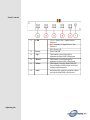
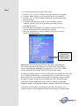
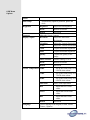
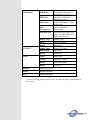
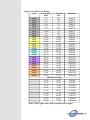
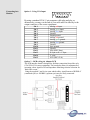
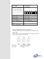
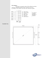
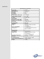
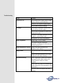
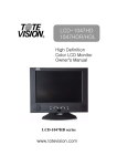
15 inch SVGA
LCD Monitor ID#15001
Operation Manual
Introduction
This is a 15 inch LCD SVGA input monitor for arcade machines and CNC
machinery retrofits. It features the VESA plug & play system which
allows the monitor to automatically adjust itself to the match the
frequency of the user's device.
Features
•
•
•
•
•
High brightness.
Fast response time.
Power saver.
Low electromagnetic wave and power saver.
Safety certifications.
•
•
The power control system is installed inside the LCD monitor.
If the monitor has not been used for a certain period of time, the
system will turn the monitor to low voltage mode to save power. Any
button press will return the monitor to original state.
Your input device e.g. your computer controls the power saver mode.
You can adjust these settings via your computer
The LCD monitor is compatible with EPA Energy Star and N Tek if
used with a VESA DPMS computer.
To save power, turn off the power of the LCD monitor when it is not
in use.
Power Saver
•
•
•
Plug and Play
•
•
•
The VESA plug and play function eliminates the complicated and
time-consuming installation process.
As this is a plug and play monitor. Your computer system can easily
identify and automatically adjust the monitor.
The LCD monitor uses Display Data Channel (DDC) to send Extended
Display Identification Data (EDID) to the computer system, so the
computer system can be set to monitor auto adjust.
Setting up your
LCD monitor
Screen Adjustment
To enter adjust mode, please refer to the OSD control.
•
•
•
•
•
•
•
•
•
•
•
•
Turn the computer and LCD monitor on.
Press “Auto” button to start auto adjust.
This will start the auto adjust process. This will take approximately 10
seconds. You may notice the image changing and occasionally
flashing (this is normal).
Your LCD monitor provides a self testing function, through which you
can check whether the LCD monitor functions are working properly.
If your LCD monitor is properly connected, but there is no image
showing and the indicator lights up in orange, please follow the below
steps:
Shutdown the computer and the LCD monitor.
Unplug the signal connector from the back of the computer.
Turn the LCD monitor on.
If the image connector is disconnected or damaged, a “No signal
input” sign will pop up on the monitor.
Turn off the LCD monitor and reconnect the signal cable, and then
turn the computer and LCD monitor on.
If the LED of the LCD monitor is an orange colour after completing
the steps above, please check your VGA card and computer system.
Your monitor should be operating properly.
If the “out of range” error pops up on the monitor, the input frequency
is outside of the specified range and will not display an image. The
correct frequency will need to be entered and then restart the monitor.
Panel Controls
Adjusting the
1.
LED
Green : Power On + Signal Source
Detected
Red : Standby or Signal Source Not
Detected
Off : Power off
Power On/Off.
2.
Power
3.
Up/+
This button is used for positive
adjustment when OSD is Displayed
4.
Down/-
5.
Menu
6.
Auto
This button is used for negative
adjustment when OSD is Displayed
This button is used to display the ON
Screen Display (OSD) menu and select
settings and parameters.
Automatically optimize positions, phase
and clock when OSD is not shown.
Image
•
•
•
•
•
•
•
Press the menu button to start the OSD feature.
Click the “Up” or “Down” button to select the function to be adjusted.
Click the “Menu” button to access into the function to be adjusted.
Click the “Up” or “Down” button to change the current setting of the
function selected.
To exit the OSD menu or go back to a previous menu click the
“Auto/Esc” button. Upon exiting the menu any changes will be
automatically saved.
The OSD menu will disappear if no buttons are pressed for several
seconds. OSD display time is adjustable to suit needs
Due to the automatic save feature, turning off the power is unwise
while navigating the menu.
Detects and
displays current
input setting
Please Note: Due to the advanced nature of this panel. Adjustments to
clock, phase and image positioning are saved only for the signal timing
you are currently using. Meaning if your input is CGA 640 x 215 @60Hz,
and you adjust the clock setting. This will only affect this timing.
So when your change input to VGA 640 x 480 @60Hz for example the clock will
be at its default (or last memory saved setting). This is to allow the user to get a
picture perfect for every input he requires and avoid redoing settings each time
the input is changed. Except for these adjustments, clock, phase and image
positioning, all other adjustments are universal for example changing the
brightness setting will change the brightness setting for all inputs and timings.
To help the User remember; all settings that only affect the timing you’re
currently using are coloured pink and the universal settings are coloured white.
OSD Menu
Options
Menu
Auto Setup
Brightness
Automatically optimize positions, phase and
clock
Brightness
Adjust Screen Brightness
Recall
Restore to Default
Return
Exit menu
Contrast
Adjust the Screen Contrast
Display Adjust
H Position
Adjust the Horizontal
Positioning
V Position
Adjust the Vertical Positioning
V Size
Adjust the Vertical Screen Size
Clock
Adjusts horizontal alignment
Phase
Adjusts horizontal alignment
Quality
Adjusts the quality of the
image
Mode Selection
Default Analog VGA in
Recall
Restore to Default
Return
Exit menu
Colour Temperature 9300k
Set up the colour temp. to be
9300 K white colour.
7500k
Set up the colour temp. to be
7500 K white colour.
6500k
Set up the colour temp. to be
6500 K white colour.
Auto Gain
Red
Adjust the Red colour
values
Green
Adjust the Green colour
values
Blue
Adjust the Blue colour
values
Return
Language
Auto Colour adjustment
Exit menu
Choose language from English, French, Italian,
Chinese, Japanese
OSD Display
VGA/DVI
Audio
OSD H-Pos
Position the OSD menu
horizontally on screen
OSD V-Pos
Position the OSD menu
vertically on screen
OSD Timer
Set the OSD menu on screen
display time
OSD
Transparency
Set the OSD menu
Transparency
OSD Direction
Set the direction of the OSD
menu : Normal, Mirror, Left,
Right, Up or Down
Display Logo
Display Logo
Recall
Restore to Default
Return
Exit Menu
Analog Input
Selects VGA input
Digital Input
Unavailable
Return
Exit Menu
Audio
Mute Audio
Volume
Adjust the volume
Recall
Restore to default
Return
Exit menu
Read me
Quick start Guide
Recall
Restore to default
Exit
Restore to default
Warning: Phase and Clock Settings shouldn’t be touched unless you know
what you’re doing. Altering these values can make the image unwatchable on
the screen
Support CGA/EGA/VGA Timings
Type
H. Frequency. V. Frequency
Resolution
(kHz)
(Hz)
CGA
15.4
58.8
640x198
CGA
15.1
57.6
640x215
CGA
15.7
60
640x215
CGA
16.0
61
640x215
CGA
16.3
62
640x215
CGA
16.6
63.4
640x215
CGA
16.800
64
640x215
CGA
15.6
50.3
640x265
CGA
18.4
50
640x350
VGA
31.469
70.087
640x400
VGA
31.469
59.940
640x480
VGA
35.000
66.667
640x480
VGA
37.861
72.809
640x480
VGA
37.500
75.000
640x480
SVGA
35.156
56.250
800x600
SVGA
37.879
60.317
800x600
SVGA
48.077
72.188
800x600
SVGA
46.875
75.000
800x600
XGA
48.363
60.004
1024x768
XGA
48.78
59.561
1024x768
XGA
56.476
70.069
1024x768
XGA
60.023
75.029
1024x768
47.732
60.024
SXGA
1280x768
60.168
75.019
SXGA
1280x768
SXGA
60.000
60.000
1280x960
SXGA
63.981
60.020
1280x1024
SXGA
79.976
75.025
1280x1024
Additional Timings
31.469
70.087
720x400
49.726
74,551
832x624
67.500
75.000
1152x864
68.681
75.062
1152x870
61.795
65.950
1152x900
71.809
76.149
1150x900
47.700
60.000
1360x768
55.935
59.887
1440x900
70.640
74.980
1440x900
Above is just a guide, many other frequencies are accepted
Connecting into
Monitor
Option 1 - Using VGA Input
By using a standard VGA 15 pin computer cable plug and play or,
alternatively you may cut the end of your cable and wire directly to the
output connector of the source equipment.
Pin 1
Pin 2
Pin 3
Pin 4
Pin 5
Pin 6
Pin 7
Pin 8
Pin 9
Pin 10
Pin 11
Pin 12
Pin 13
Pin 14
Pin 15
Analog red input.
Analog green input.
Analog blue input.
Ground.
Digital ground.
Analog red ground.
Analog green ground.
Analog blue ground.
Ground.
Sync ground.
Ground.
SDA (DDC Data).
H. Sync or H + V Sync.
V. sync.
SCL (DDC CLK).
Option 2 - RGB wiring via Adapter PCB
The PCB interface board is designed to facilitate connection from older style
CGA/EGA/VGA source equipment. The board also allows for adjustment of
incoming colour signal levels and Impedance Matching selection selection for
'black line' screen..
Using the supplied 5 and 6 wire open ended cables, signal formats of RGBH+V
(combined sync) or RGBHV (separate sync) may be easily connected.
P1 – RGBHV
separate/ or combined sync
P3 – RGBH+V
combined sync
Pin 1 – Red
Pin 1 – Red
Pin 2 – Green
Pin 2 – Green
Pin 3 – Blue
Pin 3 – Blue
Pin 4 – Signal Earth
Pin 4 – Signal Earth
Pin 5 – Horizontal/Combined
Sync
Pin 5 – Horizontal/Combined Sync
Pin 6 – Vertical Sync
About Our Adapter PCB and Further Adjustments
Our adapter PCB offers a number of adjustments via the following controls
-VR1 to VR3
Adjust to vary the level of the individual output colour signals to compensate
for over exposure/brightness of video image.
VR1 – Red
VR2 – Green
VR3 – Blue
| Adjusts colours to reduce the
| signal strength if image is
| over bright
Filter Jumpers
Set Jumpers as required to reduce effect of black line artifacts
when low resolution mismatch becomes evident on LCD screen.
By setting to “ON” position, each colour can be filtered as required.
.
C1 = Red Colour 1
C2 = Green Colour
C3 = Not used
C4 = Blue colour
C5 = Not used
C6 = Red Colour 2
Front/Side View
|
|
|
|
|
|
To adjust for
Impedance
Matching of
interfaces
Specifications
Specifications for this Model
Screen Size
15" TFT
Pixel Pitch(mm)
0.264 x 0.264
Blacklight
2xCCFL
Cell Type
TN
Input Mode
SVGA
Scan Frequency Horizontal
15 ~ 80KHZ
Scan Frequency Vertical
48 ~ 75Hz
Colours
16.7M Colors
Aspect Ratio
5:4
Horizontal Viewing Angle
Full range
Optimal Screen Resolution
1024 x 768
Bandwidth
130MHz Dot Clock
Contrast Ratio
500:1 Typ
Brightness
250cd/m2
Power
100~240V 50/60Hz via 12VDC
1.2A adapter
Power Consumption
13.35 Watts(Typ.)
Management
Vesa-Dpms 42 watts Power down
mode </=3 Watts
Function Keys
5
PC Interface
Analog Interface
Signal Cable
Standard VGA cable w/15-pin
D-sub connector.
Or via VGA Inverter PCB
Operating Temperature
0 degrees ~ +50 Degrees
Humidity
10 ~ 85%
Overall Dimensions
325mm x 258mm x 44mm
Active Screen Area Dimension
310mm x230mm
Weight
2.450kg
Troubleshooting
Error
Solution
No Power Led
Check Mains Power supply input Voltage
(100v or 240vAC) and connection
Check 12V DC at power supply output
Check control board for damage
No image
Check cables connected correctly from
source and into monitor inputs
Check correct orientation of signal wires;
H-sync and V-sync
Check for CCFL lamp operation on rear of
lcd panel, visual reference only
Check power 'on' source and monitor
Image Alignment
Adjust using “AUTO” button
Fine adjust using the OSD Menu
parameters accordingly for Horizontal and
Vertical position/size
Image Brightness/Contrast Adjust OSD Menu parameters for
Brightness and Contrast
Image colour
Check RGB colour wires connected and
active
Adjust OSD Menu parameters for colour
temperature and colour intensity
Intermittent Image
Ensure equipment is earthed and isolated
from signal earths, Note: Isolation (No
Earth) sometimes improves image
reception
Ensure open wire cables are sheathed and
earthed against EFI (Electromagnetic Field
Interference)
Check all cable pins aligned and seated
correctly