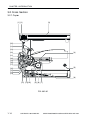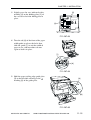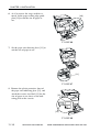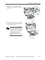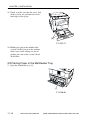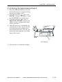
1
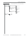
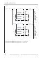
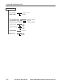
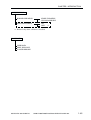
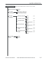
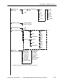
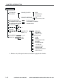
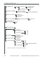
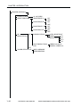
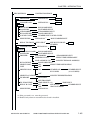
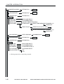
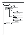
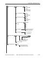
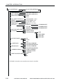
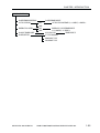
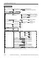
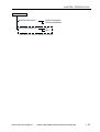
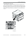
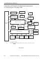
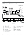
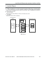
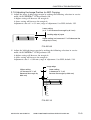
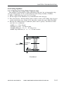
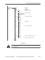
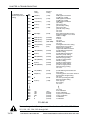
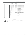
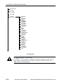
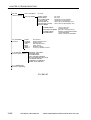
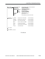
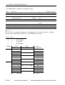
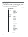
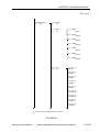
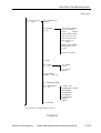
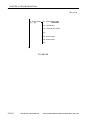
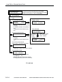
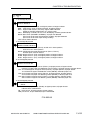
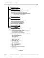
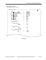
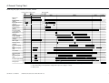
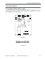
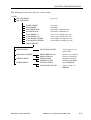
CHAPTER 1 INTRODUCTION
CONFIG MENU
JAM RECOVERY
AUTOCONT
DENSITY
ECONOMY MODE
REFINE
JOB CONTROL MENU
JOB SECURING TIME
PARALLEL MENU
PERSONALITY
BIDIRECTION
I/O TIMEOUT
USB MENU
PERSONALITY
I/O TIMEOUT
ETHERNET MENU *2
PERSONALITY
I/O TIMEOUT
Enables the printer to resume printing once a paper jam has
been cleared.
Turns the Automatic Continue function, for error handling, on
or off.
Sets the relative darkness of the printouts.
Turns Economy Mode, for reducing toner usage, on or off.
Enables the printer to enhance the quality of the printouts.
Sets the length of time a secured job is held on the printer.
Set the default print personality for the parallel interface.
Specifies whether or not to use bidirectional control.
Sets the timeout interval for print jobs received via the parallel
interface.
Sets the default print personality for the USB interface.
Sets the timeout interval for print jobs received via the USB
port.
Sets the default print personality for the optional network interface board.
Sets the timeout interval for the optional network interface
board.
LANGUAGE MENU
LANG
Sets the default language for the LCD display on the printer.
REST MENU
RESET
Resets the selected settings to their default values.
JOB LOG MENU
AUTO PRINT LOG PER 50/30 JOBS
Specifies whether or not to automatically print the job log.
AUTO CLEAR LOG EVERY 50/30 JOBS
Specifies whether or not to automatically clear the job log.
JOB LOG FULL
Sets the default action for when the job log becomes full.
GMT DIFFERENTIAL TIME Displays the time difference from Greewich Mean time.
DAYLIGHT SAVING TIME
Displays whether or not to use daylight saving time.
*1: displays only after the Adobe PS3 Module-B1 has been installed.
*2: displays only after the network interface board has been installed.
COPYRIGHT © 2002 CANON INC. 2001 2001 2001 2001 CANON Printer Board-N1/iN-E5 REV.0 MAR. 2002
1-5