1
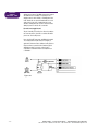
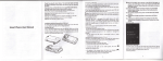
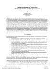
Amplifier
MDM-7™ High
Performance Stepping
Motor Drive Module
MDM-7™ Drive Module Operator’s Manual
Overview
Thank you for selecting Danaher Motion as your positioning
equipment supplier. We understand that you can choose from a
number of competitive suppliers, and are pleased that you have
selected DPS.
Our Customer Service department can be reached at:
This manual addresses the MDM-7™ Drive Module. As you
unpack and begin to use our product, we would like your conclusions as to our products’ appearance, quality, precision, and suitability to your ultimate application. By providing us with feedback
in these and other areas, you can become an active participant in
our on-going program of continuous improvement.
We encourage you to visit our web site at
www.danaherprecision.com. It includes information on new
products, along with our existing product catalog, a Motion
Control Handbook covering 33 technical topics, and other
useful information.
phone: 603.893.0588 or 800.227.1066 fax: 603.893.8280
e-mail: [email protected]
Thank you again for choosing Danaher Motion. We look forward
to serving you in the future.
Features
• Compact 4.5”w x 4.0”h x 0.8”d package
• High speed operation, to 150 revs/second
• Complete mid-range resonance suppression
• Optically isolated inputs
The MDM-7 stepping motor drive module provide compact,
high performance solutions to stepping motor drive requirements. The MDM7 divides each full step into 10 microsteps,
providing 2000 steps per revolution from standard 1.8 degree
stepping motors and features high speed bipolar chopper output stages, capable of running stepping motors at speeds in
excess of 150 revolutions per second. Use of efficient MOSFET
output devices results in minimal drive heating; in many cases,
no additional heat sinking is required.
The MDM-7 module features full compensation for mid-range
resonance. Most available stepping motor drives (especially
microsteppers) overlook this problem, which accounts for many
application-killing “stalling” or “resonance” complaints. The
microstepping MDM-7 module provides a factor of 10 increase
in system resolution overfull stepdrives, with no trade-off in
high speed performance. It also provides exceptionally smooth
low speed motion, nearly eliminating noise and vibration in the
0 to 2 rev/sec speed range. Due to the efficient recirculating
design of these drive modules, overall power supply requirements are reduced to only 1/3 of the motors rated phase current full coil) or 2/3 of the rated value (half coil).
The MDM-7 module operates from unregulated supply voltages
between 24 and 60 volts D.C., and can drive motors rated at up
to 3.5 Amps per phase (half coil) or 7.0 Amps per phase (full
coil). Use of this module at high shaft speeds will require commensurately high step pulse rates (200 KHz for 100 rev/sec.);
ideal companion indexer boards for the IBM-PC are our PCX
cards, which generate step rates of up to 524kHz. Motor current is adjustable via an external 1/4 watt resistor; resistor val-
ues for a wide range of current settings, as well as all necessary wiring details, are screened onto each module. If desired,
idle current reduction can be easily implemented with external
logic. Opto-isolators on the TTL compatable input lines provide
effective isolation from noise-sensitive logic or CPU-based
controllers. All wiring terminations are made via convenient
screw-clamp terminal strips. Housed in compact, rugged metal
enclosures 4.5” wide x 4.0” high x 0.8” deep, these drive modules mount easily to any flat surface.
Contents
Connector Details . . . . . . . . . . . . . . . . . . . . . . . 2
Full Coil versus Half Coil. . . . . . . . . . . . . . . . . . 3
Microstepping . . . . . . . . . . . . . . . . . . . . . . . . . . 7
Midrange Resonance . . . . . . . . . . . . . . . . . . . . 8
Summary . . . . . . . . . . . . . . . . . . . . . . . . . . . . . . 8
Warranty & Terms . . . . . . . . . . . . . . . . . . . . . . 10
Danaher Motion • Precision Systems Group • 7C Raymond Avenue, Salem, NH 03079
tel: 603.893.0588 • toll free: 800.227.1066 • fax: 603.893.8280 • url: www.danaherprecision.com
–1–
MDM-7™ Drive Module Operator’s Manual
Connector
Details
All MDM-7 module functions are brought out on a single 12 pin
screw-clamp style connector. To attach leads to the connector,
simply insert solid or standard wire in the 18 to 26 gauge range
and tighten the screw clamp. Specific pin functions are detailed
below.
Pin #1: Power Supply Ground
This pin, which is internally tied to pin #12, is to be connected to
the user provided D.C. power supply ground. Power supply
ground should be connected to the chassis to which the module
is mounted. To minimize radiated EMI (electrical noise), this
ground should also be connected to the shield enclosing the
motor leads. This shield should be extended to the motor case,
minimizing electrical noise generation by the motor.
Pin #2 Power Supply V+
This pin is to be connected to the user provided D.C. power supply positive lead. This supply need not be regulated, and can
range from +24 to +60 volts D.C. Care must be exercised that
power line fluctuations and power supply ripple do not exceed
the 60 volt maximum rating. For best operation, power supply ripple should be held to 1 volt peak to peak or less. High speed
torque and power are proportional to the D.C. supply value;
accordingly, higher supply voltages will provide increased performance. The penalty paid for this performance is increased motor
and module heating, as well as increased power supply weight
and volume.
Due to the efficiency of the recirculating drive design, total power
supply current requirements are reduced to approximately 1/3 of
the motors phase current rating for full coil operation, and 2/3 of
the current rating for half coil operation (for information on the
meaning of the terms “full coil” and “half coil,” (see next page).
These current requirements are significantly reduced at idle, light
torque loading, and low speeds.
Amps per phase, and operated in half coil mode, will require a
D.C. supply current of 2/3 * 2.6, or 1.73 Amps. This corresponds to
a transformer secondary current rating of 2.45 Amps A.C. The filter capacitors value, in microfarads, should equal 8000 times the
D.C. supply current (14000 microfarads in the above example) to
ensure a ripple voltage below 1 volt. Smaller capacitors will also
work, but result in increased supply voltage ripple. This can
impair performance if the motor is required to produce close to
its maximum torque output.
A 5 Amp, fast blow fuse must be inserted in the positive side of
the D.C. power supply, to protect against motor shorts to ground,
etc. As described below, the motor MUST be wired in place
before D.C. power is applied. Never connect or disconnect the
motor while D.C. power is applied. The power supply leads (V+
and GND) should be kept as short as possible. If these leads
exceed 10 inches, install both a .1 mfd. and 100 mfd. capacitor
rated at 100 volts or higher across pins #1 and #2 at the drive
module.
Pins #3 and 4: Motor Coil 1
Pins #5 and 6: Motor Coil 2
WARNING! No connection or disconnection of the motor leads
should be performed while the module D.C. power supply is
active. Always wire the motor leads prior to applying D.C. power.
If connectors are present along the motor cable, always turn off
D.C. power prior to connecting or disconnecting the motor. The
extremely high voltage, fast rise-time transients produced when
the motor is connected or disconnected can destroy the FET output stage of the MDM-7 module. Damage caused by motor connection/disconnection with power applied is not covered under
the DPS warranty.
For users building their own unregulated D.C. power supplies, Fig.
1 details a typical design. It consists of an A.C. line filter, A.C.
fuse, on-off switch, transformer, diode bridge, filter capacitor, and
D.C. fuse. The transformer primary voltage should coincide with
the line voltage (115 V.A.C. or 230 V.A.C.), while the transformer
secondary voltage should equal .7 times the desired D.C. supply
voltage (for example, a transformer secondary voltage of 30 volts
A.C. will be required for a D.C. supply voltage of 42 volts). The
secondary current requirement should be 1.4 times the desired
D.C. supply current. For example, a stepping motor rated at 2.6
Figure 1
–2–
Danaher Motion • Precision Systems Group • 7C Raymond Avenue, Salem, NH 03079
tel: 603.893.0588 • toll free: 800.227.1066 • fax: 603.893.8280 • url: www.danaherprecision.com
Since most stepping motors are six lead devices, and the
MDM-7 drive has four output leads, two leads must be left
unconnected. The choice of which two leads to leave unconnected has distinct performance impacts, as described below.
Stepping motors are normally wired as two center-tapped coils
(six leads total). Our pins #3 and 4 (similarly #5 and 6) can be
wired across the full coil, leaving the center tap disconnected,
or across a coil end and the center tap, leaving the other coil
end disconnected. These two possibilities are referred to as
“full coil” and “half coil,” respectively.
Operation in full coil mode doubles the number of winding turns
and quadruples the winding inductance (compared to half coil
operation). Accordingly, the current setting resistor (see below)
should be set to one-half the rated (nameplate) motor current
value for “full coil” operation (the nameplate value assumes
unipolar, half coil operation). Heating of the drive module and
motor will be half that experienced in half coil mode. Power
supply current requirements are also cut in half. On the downside, motor torque will fall off faster at higher speeds. The
graph of motor torque versus frequency can be broken into two
regions: a low speed region within which torque is constant,
and a high speed region within which torque is inversely proportional to frequency. The onset of the “break” between the
two regions will be halved in full coll mode, and the torque at
any given high speed will be half that available-in half coil
mode. The chart below summarizes the differences between
full and half coil modes.
The basic conclusion is that for high speed performance, half
coil mode should be employed. If low to moderate speeds are
adequate, and especially if heating or supply current are of
concern, full coil operation is preferable. The pair of leads
which remain unconnected should be insulated to avoid shorts
or shocks; under some circumstances voltages of up to 120
volts can appear on these leads. There is no specific rule as to
the order of the four remaining leads and our terminals #3, #4,
#5, and #6 (excepting, of course, that pins 3 and 4 must run to a
motor coil and not to each end of two separate motor coils).
Reversing any two of the four motor leads will result in a direction reversal relative to the state of the direction line.
Full Coil
versus
Half Coil
w
t
t
Accordingly, if your system “runs the wrong way,” reversing
any pair of motor leads (after carefully powering down the D.C.
supply) will reverse the system direction sense. This is considerable easier than inverting the level of the direction line via
hardware. The color conventions for several stepping motor
manufacturers are shown on the next page
A
H
h
t
In this chart, I is the rated (nameplate) current; L is the rated
inductance; R is the rated resistance; V is the drive supply voltage; f is the step frequency; T is the holding torque, and k is a
motor-specific constant of proportionality. Since high speed
torque is proportional to the D.C. supply voltage, full coil operation at 50 volts will result in the identical performance as half
coil operation at 25 volts.
h
b
t
t
Full Coil
Half Coil
Drive Current Setting
0.5 I
I
D.C. Supply Current
0.33 I
0.66 I
Drive Heating (low speed region)
0.15 I2
0.6 I2
Drive Heating (high speed region)
0.03 I2
0.1 I2
Coil Inductance
4L
L
Coil Resistance
2R
R
0.5f break
f break
Low Speed Torque
T
T
High Speed Torque
kVT/2f
kVT/f
Speed/Torque Break Point
Danaher Motion • Precision Systems Group • 7C Raymond Avenue, Salem, NH 03079
tel: 603.893.0588 • toll free: 800.227.1066 • fax: 603.893.8280 • url: www.danaherprecision.com
–3–
Full Coil
versus
Half Coil
PHASE 2
PHASE
2-4
CENTER TAP
PHASE 4
PHASE 1
PHASE
1-3
CENTER TAP
PHASE 3
Manufacturer
Rapidsyn
Figure 2
Phase 1
Phase 1-3 C.T.
Phase 3
Phase 2
Phase 2-4 C.T.
Phase 4
Red
Black
Red/White
Green
White
Green/White
Superior
Red
Black
Red/White
Green
White
Green/White
Oriental
Black
Yellow
Green
Red
White
Blue
Sigma (Pac-Sci)
Black
Black/Orange/White
Orange
Red
Red/Yellow/White
Yellow
Bodine
Brown
White/Brown
Orange
Red
White/Red
Yellow
Pin #7 Full/Half (SDM7)
No Connect (HDH7)
This pin should be left unconnected on the microstepping
MDM-7 drive. Half step mode double the resolution, providing
400 steps per revolution from standard 1.8 degree stepping
motors. The default (unterminated) state of this line selects full
step; if it is connected to Power Supply Ground (pin #1 or pin
#12) the motor will operate in half step mode. Note that this
input is not opto-isolated and is referenced to Power Supply
Ground. The choice of which drive mode (full or half step) to
use is usually a one time decision; this pin wil either be left
floating or be tied to pin #1 or #12. If dynamic control of this pin
is desired, an opto-isolator may be used to short the pin to
power supply ground, while maintaining isolation from the control circuitry.
The principal benefits of half-stepping are the doubling of resolution and increased smoothness during low speed operation.
The step rate for any given motor shaft speed will be twice as
high as that required for full step operation. The primary resonance of stepping motors, which occurs between 1/2 and 2
–4–
revolutions per second, results in noisy operation and the
potential for lost steps near these speeds. Half step operation
is very effective in reducing the effect of this resonance. Our
microstepping MDM-7 drive provides even higher suppression
of the primary resonance, and smoother low speed operation.
Pin #8 Direction
This pin sets the direction of motor rotation for subsequent
step pulses. The level on this pin must be established at least
100 microseconds prior to issuing step pulses. The correlation
between the level at the Direction pin and the direction of
motor rotation varies with the coil connections to pins #3 to #6;
the specific equivalence for Rapidsyn and Superior motors is
as follows: if pins #3, #4, #5, and #6 are wired to motor lead
colors red, black, green, and white respectively, then a low
level applied to the Direction pin will result in counterclockwise
rotation, as viewed facing the stepping motor drive shaft.
For other motor manufacturers, wire the motor and check;
as described above, simply reversing any pair of motor leads
(after carefully shutting off D.C. power) will reverse the
direction sense.
Danaher Motion • Precision Systems Group • 7C Raymond Avenue, Salem, NH 03079
tel: 603.893.0588 • toll free: 800.227.1066 • fax: 603.893.8280 • url: www.danaherprecision.com
The circuit path for the Direction line is screened on the
module exterior; it begins at the user supplied +5 volts (pin
#10), flows through the internal opto-isolator LED and resistor,
and is brought out at the Direction pin (#8). Accordingly, the
default (unterminated) state of this input is a logic high (+5
volts). The Direction input must accordingly be driven by a
device capable of sinking current; 16 milliamps is required
to turn on the opto LED. A typical I.C. which meets these
requirements is a TTL 7406 or 74LS06; most other TTL chips
are also capable of sinking 16 milliamps. Note that the
Direction (and Step Pulse) lines are opto-isolated; whenever
possible, the ground for the device driving the Direction line
should be isolated with respect to Power Supply Ground. In
this manner, the controlling circuitry (often a noise sensitive
CPU based system) will be totally isolated from the motor
drive circuits.
Pin #9 Step Pulse
The stepping motor will rotate one step (full, half or microstep,
depending on model and mode of operation) for each falling
edge (high to low transition) received on the Step Pulse input.
The direction of rotation will depend on the level on the
Direction line, as previously discussed. The electrical characteristics of the Step Pulse input are identical to those of the
Direction input (see above), with the one exception that transitions must be rapid in nature; the high to low transition should
occur in 200 nanoseconds or less. Slow transition devices such
as most opto-isolators, op-amps, etc. are too slow and should
not be used. The minimum duration of the Step Pulse line in
either the low or high state 1 is microsecond. This results in a
maximum input frequency of 500 kHz. Many pulse generators
will be incapable of producing such high frequency pulse
trains (our PCX card for the IBM-PC is an exception, with a 524
kHz maximum step rate). 300 kHz corresponds to a shaft rotation rate (using the divide by 10 HDM7) of 150 revolutions per
second, or 9000 rpm. While little usable shaft power remains at
such speeds, the ability of our MDM7 to run stepping motors at
such speeds (a 50 volt power supply and a modest acceleration helps) demonstrates the inherently high performance of
these drives. The SDM7 will perform similarly with a 30 KHz
input step rate. Note: Do not bundle the Step and Direction signals within the same cable as the motor leads; this may result
in signal noise and erratic operation. Use separate cables, and
employ a shield around the motor leads; this shield should be
tied to Power Supply Ground and the module case.
Pin #10 .5 Volts D.C.
The user must provide +5 volts D.C. to this pin to operate the
opto-isolators. The circuit path shown on the module exterior is
all that this +5 volt supply operates; the aurrent requirement is
accordingly ~35 milliamps. As previously noted, this +5 volt supply
should be floating (isolated) with respect to Power Supply
Ground to fully utilize the isolation provided by the opto coupled
inputs.
Full Coil
versus
Half Coil, cont.
Pin #11 Current Set
The motor current is determined by the value of a 1/4 watt
resistor which is installed between pins #11 (Current Set) and
#12 (Power Supply Ground). The value chosen for this resistor
is a function of the motors rated (nameplate) phase current and
the coil drive mode (full coil or half coil).
The relationship between motor rated current, drive mode, and
resistor value is as follows:
Current Set Resistor Table
Pull Coil
1.5A
2.0A
2.5A
3.0A
3.5A
4.0A
4.5A
5.0A
5.5A
6.0A
6.5A
7.0A
Half Coil
.75A
1.00A
1.25A
1.50A
1.75A
2.00A
2.25A
2.50A
2.75A
3.00A
3.25A
3.S0A
Resistor
12K
15K
27K
33K
47K
68K
82K
120K
180K
270K
560K
3.3M
The above chart is also screened onto the exterior of the drive
module. As an example, a popular 100 oz-in motor is rated at 1.8
Amps per phase. Operation in half coil mode will require a 47K
ohm resistor, while full coil operation will require a 12K or 15K
ohm resistor. The highest motor phase current operable with
these modules will be 7.0 Amps per phase, although motors of
this current rating could only be run in full coil mode. To preserve the highest possible microstep uniformity when using the
MDM-7 drive, do not vary the resistor value from that indicated
in the table. If you happen to be using a 4 lead motor, the rated
(nameplate) current rating will correspond to the half-coil column resistor value. Note that while the resistor sets the motor
operating current (and hence torque) at standstill and throughout the low speed region (see above), high speed torque is
inductively limited and hence independant of the specific resistor setting.
In some applications, it may be desirable to lower the motor
current when stationary, restoring it to its full value only when a
move is required. This can be achieved by paralleling a second
resistor with the current set resistor. Total torque shut-off can
be achieved by applying a short (zero resistance) across the
current set resistor. Since the Current Set pin is referenced to
Power Supply Ground, an opto isolator will be necessary if full
isolation is to be preserved. A typical implementation is shown
in Figure 03:
In applications where full acceleration torque is required,
enabling full current 10-20 milliseconds before initiating a move
Danaher Motion • Precision Systems Group • 7C Raymond Avenue, Salem, NH 03079
tel: 603.893.0588 • toll free: 800.227.1066 • fax: 603.893.8280 • url: www.danaherprecision.com
–5–
Full Coil
versus
Half Coil, cont.
will improve performance. The MDM-7 drive module is shipped
with a l5K ohm resistor installed, corresponding to a 1.0
Amp/phase motor in half coil mode, or a 2.0 Amp/phase motor
in full coil mode. Do not operate the module without a current
setting resistor. If the resistor is omitted, the drive current
defaults to 3.5 Amp/phase (half coil). This could overheat and
damage any motor not rated for this current value.
Pin #12 Power Supply Ground
This pin is internally connected to pin #1. Due to its proxiaity to
the Current Set pin (#11), it provides a convenient attachment
point for the current setting resistor.
Due to its efficient FET output stage, the MDM-7 drive module
can be simply bolted to any flat surface in the majority of
applications, without the need for additional cooling provisions.
High current motors operated in half coil mode may require
additional heat sinking or forced air cooling; the basic
requirement is to maintain the module case temperature at
or below 60°C.
Figure 03
–6–
Danaher Motion • Precision Systems Group • 7C Raymond Avenue, Salem, NH 03079
tel: 603.893.0588 • toll free: 800.227.1066 • fax: 603.893.8280 • url: www.danaherprecision.com
Microstepping
The MDM-7 drive implements microstepping at the divide by 10 level;
that is, it electronically subdivides each full step into 10 microsteps.
This provides two distinct benefits: the system resolution is increased
ten-fold, and the noise and vibration associated with step rates at or
below the fundamental resonance is greatly reduced. In leadscrew
based systems, microstepping allows fine resolutions to be achieved
with relatively coarse leadscrews; this permits high linear velocities
which would be unattainable with fine pitch leadscrews in full or half
step systems. The benefits of microstepping are best realized at relatively modest division ratios; popular systems which divide full steps
into as many as 256 microsteps provide “empty resolution,” with limited practical advantages. The step rates required to operate such systems at high shaft rotation rates are usually beyond the capability of
typical pulse sources. Our divide by 10 level of microstepping has
been chosen as optimal for most real world applications.
Midrange resonance is a parasitic oscillation of the stepping motor
rotor from its intended position, which occurs while the motor is
rotating. It generally sets in at shaft rotation rates between 5 and 15
revs/sec. (1000 to 3000 full stepstsec. for standard 1.8 degree steppers). Depending on the frictional and inertial aspects of the load,
midrange resonance may or may not occur in any given application.
When viewed across a broad range of applications, midrange resonance constitutes a serious problem for stepping motor based systems. In many examples where the system is incapable of exceeding
5 –10 revolutions per second, the actual cause is stalling due to
midrange resonance. The effect usually manifests itself as a 50–150
Hz vibration which builds in amplitude over 1/2 to 2 seconds, terminating in a stalled motor and loss of position. Most commercially
available stepping motor drives ignore this problem, and may call for
bizarre mechanical fixes such as “hang a drill chuck on the motor
rear shaft,” Lancester dampers, etc. The DPS MDM-7 drive incorporates circuitry which senses the onset of midrange resonance and
introduces the electronic equivalent of viscous damping to eliminate
the problem. As a result, all motor torque is available for accelerating
the load, as opposed to being wasted driving spurious resonances.
One minor requirement of this circuitry is that the incoming step
pulse train should be smooth - errative variations of more than 15%
between successive step pulses (which can be encountered in
unsmoothed binary-rate multiplier pulse generators) can confuse the
compensation circuitry. This problem is rarely encounter in practice.
Pulse width modulated microstepping drives typically
produce some broad-band audible noise when at a
standstill. The physical basis for these phenomena is
intrinsic to the products’ design, and occurs as follows:
Two free-running oscillators generate the pulse width
modulated sine and cosine coil currents needed for
microstepping. While nominally operating at 20 KHz,
their actual frequency is second order dependent on
coil current and load, and may free-run from 18 to 24
KHz. At the 45 and 225 electrical degree points, the sine
and cosine values are equal, and the PWM frequencies
become equal. When the frequencies are nearly equal,
the two oscillators may “lock” and begin oscillating in
phase. Despite the design objective of decoupling the
oscillators, small currents due to reverse recovery, output switching, and MOSFET gate charging may provoke
a phase lock between them. This phase lock leads to a
small but growing error, and when the servo of the error
amp detects the deviation, it “breaks” the phase lock. If,
for example, the oscillators are in lock for 9 cycles and
break for 1, the result will be an audible 2 KHz beat
product of the 20 KHz nominal frequency.
Midrange
Resonance
Microstepping
Induced Motor
Shaft Vibration
& Audible Noise
The effect has been a largely unavoidable effect of
generic microstepping driver designs; a new design
utilizing fixed frequency oscillators is now available
for divide by 1-2-10-20-25-50-100-200 microstepping
resolutions.
Summary
The fixed frequency oscillator design significantly
reduces stepping motor shaft vibration and audible
noise while substantially reducing motor heating due
to iron losses.
Summary
The MDM-7 module is the best possible drive module which we currently provide. Its combination of compact size, high speed performance, ease of mounting, wiring, microstepping cabability, midrange
resonance suppression, opto-isolated inputs, and 3.5/7.0 Amp/phase
drive capability is unmatched in any other commercially available
stepping motor drive. This allows users to simply “drop-in” a small,
high performance drive which will extract the maximum torque
stepping motors can provide. We are interested in your reactions
and comments, as welll as suggestions for future improvement.
Danaher Motion • Precision Systems Group • 7C Raymond Avenue, Salem, NH 03079
tel: 603.893.0588 • toll free: 800.227.1066 • fax: 603.893.8280 • url: www.danaherprecision.com
–7–
4 50”
4.50
.187”
.187”
3 612”
3.612
4.00
0 ”
.187”” DIA. THRU HOLES, 4 PLACES
.187”
SPECIFICATIONS
Parameter
Minimum
Maximum
Units
Supply Voltage
24
60
volts D.C.
Supply Current (no motor)
50
60
mA
Pin
Function
PWM Frequency
18
24
KHz
1
Power Supply Ground
Motor Current (half coil)
0.75
3.5
Amperes
2
Power Supply +V (24–60 VDC)
Motor Current (full coil)
1.50
7.0
Amperes
3
Motor Phase A
Step Pulse High Level
1
—
µ sec
4
Motor Phase B
Step Pulse Low Level
1
—
µ sec
5
Motor Phase C
Step Frequency
—
500
KHz
6
Motor Phase D
Step Pulse Rise & Fall Time
—
0.5
µ sec
7
Full/Half Input (N.C. on module)
Step/Direction Logic High
1.8
5
volts D.C.
8
Direction Input
Step/Direction Logic Low
0
0.8
volts D.C.
9
Step Pulse Input
Step/Direction Low Level Current
12
20
mA
10
+5 Volts D.C. Input
–20°
+60°
C
11
Current Set Resistor
0
100
% RH
12
Power Supply Ground
Operating Temperature
Operating Humidity
PIN-OUT
Weight: 1 lb, 2 oz
Dimensions: 4.5" wide x 4.0" high 8" deep
–8–
Danaher Motion • Precision Systems Group • 7C Raymond Avenue, Salem, NH 03079
tel: 603.893.0588 • toll free: 800.227.1066 • fax: 603.893.8280 • url: www.danaherprecision.com
Warranty and Terms
Danaher Precision Systems (DPS) warrants to original equipment manufacturers, distributors and industrial and commercial users of its products that each new product manufactured or supplied by DPS shall be
free from defects in materials and workmanship. DPS’s sole obligation
under this warranty is limited to furnishing without additional charge a
replacement for, or at its option, repairing or issuing credit for any product which shall within one year from the date of sale by DPS be returned
freight prepaid to the plant designated by DPS and which upon inspection is determined by DPS to be defective in materials or workmanship.
Complete information as to operating conditions must accompany any
product returned for inspection. The provisions of this warranty shall not
apply to any DPS product which has been subjected to misuse, improper
operating conditions or which has been repaired or altered. Seller
makes no warranty that its products are fit for the use or purpose to
which they may be put by the buyer, whether or not such use or purpose
has been disclosed to seller in specifications or drawings previously or
subsequently provided seller, and whether or not seller’s products are
specifically designed and/or manufactured for this purpose. THIS WARRANTY IS IN LIEU OF ALL OTHER WARRANTIES, EXPRESSED OR
IMPLIED, INCLUDING ANY IMPLIED WARRANTY OF MERCHANTABILITY OR FITNESS FOR A PARTICULAR PURPOSE. DPS’s sole liability on
any such claim of any kind, whether in contract, tort or otherwise, for
any loss or damage arising out of, connected with, or resulting from the
manufacture, sale, delivery or use of the products sold thereunder shall
in no case exceed the cost of replacement or repair as provided herein.
IN NO EVENT SHALL DPS BE LIABLE FOR ANY SPECIAL, INCIDENTAL
OR CONSEQUENTIAL DAMAGES. There are no other warranties,
expressed or implied, made by DPS except the warranty against defects
in materials and workmanship set forth above and neither assumes nor
authorizes any other person or firm to assume for it any other obligations
or liability in connection with its products.
Claims for incorrect or defective materials must be received in writing
within thirty (30) days from delivery at buyer’s place of business. No
units or systems may be returned, in or out of warranty, without first
issuing a purchase order and obtaining a return authorization number
from the seller, and no claim will be allowed nor credit given for units
or systems returned without such approval. Buyer will not be allowed
to debit accounts. All credits must be issued by seller. Units which
have been exposed to hazardous or toxic materials must be decontaminated at the expense of the Purchaser before being returned.
Equipment that has not been decontaminated and certified will not be
accepted for repair. After approval from DPS, the defective unit or
system is to be returned to the factory with a written statement of
the problem and transportation prepaid. (No C.O.D. or collect freight
shipments will be accepted). After DPS’s in-plant examination,
warranty or out-of-warranty status will be determined. If upon examination of such unit or system, warranted defects exist, then the unit
or system will be repaired at no charge and shipped prepaid back to
the buyer, via common carrier. If an out-of-warranty situation exists,
the buyer shall be notified of the repair cost immediately. At such time,
the buyer must issue a purchase order to cover the cost of the repair
or authorize the unit or system to be shipped back as is, at the buyer’s
cost. Warranty work will be suspended when owner/user is in default
of financial obligation to seller.
Unless express shipping instructions are furnished by buyer, seller will
use its discretion. All shipments are F.O.B. seller’s plant. Upon delivery to
a common carrier, title and all risk of loss or damage in transit shall pass
to buyer.
If the system or unit cannot be made functional by no-charge telephone assistance or purchased replacement parts, and cannot be
returned to the DPS factory for repair, then the following field service
policy will apply: DPS will provide an on-site field service representative in a reasonable amount of time, provided that the customer issues
a bonafide purchase order to DPS covering all transportation and sub-
sistence costs and the prevailing cost per hour (eight hour minimum)
including travel time necessary to complete the repair, regardless of
warranty determination. If the DPS field service representative determines during his on-site repair that the system or unit’s problem is not
warranty-related, then the prevailing service charge per hour (eighthour minimum) shall be assessed against the issued purchase order.
Cancellation of orders consisting of standard products, for any reason, is
subject to a minimum fifteen (15) percent cancellation charge. All stan-
dard, non-standard products, custom products, or systems are subject to
a cancellation charge to be determined by DPS.
Any order placed with DPS that has more than one delivery date for
the same line item shall be termed a Blanket Order, and is is subject
to the following conditions:
• Specific ship dates must be given for the entire quantity of each
item when an order is placed. DPS must receive written confirmation of a purchase order verifying these dates.
• The entire quantity of each item on an order must be shipped within
12 months of receipt of order.
• DPS reserves the right to refuse any rescheduling of delivery dates.
• Quantity increases to items on existing orders may not be subject to
the same quantity discount as given on the original order.
Terms and
Conditions
Custom design work performed by DPS will be subject to engineering
charges. Payments are due upon acceptance of the custom design
work. DPS will retain all copyright and other proprietary rights to the
product and any additional custom work. The Purchaser shall respect
the proprietary rights of DPS and shall take measures to prevent unauthorized disclosure of information relating to the product and any additional custom design work. DPS shall retain all proprietary rights and
shall have the right and authority to use, sell, market, research, and utilize for any other purpose at it sole discretion said product and custom
design work without notification or any liability whatsoever, including
but not limited to monetary remuneration, to the Purchaser.
Prices in this quotation do not include any taxes or charges of any
nature imposed by any governmental authority which shall become
payable by reason of sale, purchase, delivery, storage, processing, use,
consumption, or shipment of equipment hereunder. All such taxes or
charges shall be the obligation of the buyer and may be either billed to
the buyer separately, or added to the price of the equipment shipped.
Returning
Goods Procedure
Shipping/Risk
of Loss
Field Service
Policy
Order
Cancellation Policy
Blanket Order
Policy
Prices and specifications are subject to change without notice.
Danaher Motion • Precision Systems Group • 7C Raymond Avenue, Salem, NH 03079
tel: 603.893.0588 • toll free: 800.227.1066 • fax: 603.893.8280 • url: www.danaherprecision.com
–9–
©2003 Danaher Motion
– 10 –
p/n 41-0060
09/2003
Danaher Motion • Precision Systems Group • 7C Raymond Avenue, Salem, NH 03079
tel: 603.893.0588 • toll free: 800.227.1066 • fax: 603.893.8280 • url: www.danaherprecision.com