1
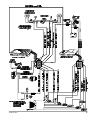
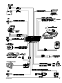
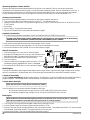
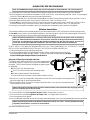
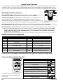
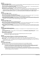
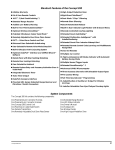
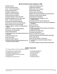
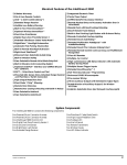
Standard Features of the AvantGuard 4
❐ Lifetime Warranty
❐ User-Selectable AutoUnLock
❐ His & Hers ACG™ 2 (Anti-CodeGrabbing™) Remote
Controls
❐ Remote Panic with Smart Locking/Unlocking
❐ Integrated Electronic Timer
❐ Extended Range Receiver
❐ Built-In Dual Parking Light Flasher with Onboard Relay
❐ Audible Low Remote Control Battery Warning
❐ Remote-Controlled Courtesy Lighting
❐ Digital Tilt/Motion Sensor
❐ Smart Remote Trunk Release
❐ Built-In Two-Point Immobilizer™
❐ Patented Smart AutoTesting™
❐ Failure Proof Driving Safety
❐ Patented Malfunction AutoBypass™ with
AutoReMonitoring
❐ Wireless Immobilizer™
❐ Remote Engine Starting - Manual or Automatic
Transmissions, Gas or Diesel
❐ Enhanced User-Selectable AutoArming
❐ AutoArm & Lock
❐ Digital Dual-Zone Proximity Sensor 4
❐ Eight-Event TotalRecall™
❐ NightVision™ Headlight Automation
❐ Patented Smart Prior Intrusion Attempt Alert
❐ Built-In Remote Headlight Activation
❐ Clear All Remotes
❐ Patented UltraSecure Coded Valet Mode™
❐ Multiple-Car Control
❐ User-Selectable Remote Valet Mode Entry/Exit
❐ Remote Keyless Entry and Accessory Activation Even in
Valet Mode
❐ FACT — False Alarm Control and Test
❐ Built-In Window RollUp
❐ Built-In BlackJax Anti-Carjacking System
❐ Self-Powered SmartSiren 4
❐ High-Luminescence LED Status Indicator with Automatic
Battery-Saving Mode
❐ Multiple Sensor/Trigger Inputs
❐ Patented SmartPowerUp™ 2
❐ Full-Time SecureAccess™ Programming
❐ Advanced CMOS Microcomputer
❐ QuietChirp™/LoudChirp™
❐ Patented Remote Control Code Learning and
Multiremote Recognition
❐ Remote Siren Silencing
❐ Pre-Loomed Wiring
❐ Optional DataPort™ Interface and CliffNet Wizard™ Pro ❐ Three Accessory Outputs with Selectable Output Types
Installation Software
❐ AutoActivation of Auxilliary Output
❐ CliffNet DataPort Accessory Interfacing
❐ Installer-Selectable Door Ajar/Delayed Courtesy Lights
❐ Remote Door Locking/Unlocking with Built-in Relays
❐ Prewired LED, Sensor, Siren, Extended Range Receiver,
❐ User-Selectable AutoLock
and PlainView 2 Switch Connectors
System Components
One prewired 24-pin connector
One prewired 12-pin connector
One prewired 14-pin connector
One prewired 9-pin connector
One AvantGuard 4 Control Unit
One Self-Powered SmartSiren 4
One Wireless Immobilizer
One NightVision Light Sensor
One IntelliStart 4 Control Unit
Two remote transmitters
AvantGuard 4/699
One Extended Range Receiver
One LED
One PlainView 2 Coded Valet Switch
One Digital Tilt/Motion Sensor
One Warranty Card
One Owner’s Manual
One Wireless Immobilizer Location Form
One Hardware Kit
Two Window Decals
One Digital Dual-Zone Proximity Sensor 4
1
AvantGuard 4 Control Unit: Wiring Description for the 12-Pin Pigtail Connector
Pin Color
Connects to
1
2
3
4
5
6
7
8
9
10
11
12
Battery positive (30-amp fuse) headlight input (+)
Window Switch 2
Window Motor 1
Window Switch 1
Battery positive (30-amp fuse) window input (+)
Key side starter
Headlight output
Coil side - ignition
Window Motor 2
Starter side - starter
Key side ignition
Parking light output
Red/White
White/Orange
Violet
White/Violet
Red
White/Green
Red/Black
Green/Blue
Orange
White/Blue
White/Brown
Brown
IntelliStart 4 Control Unit: Wiring Description for the 9-Pin Pigtail Connector
Pin Color
Connects to
1
2
3
4
6
7
8
9
Accessory
Battery positive (30-amp fuse)
Ignition 2
Coil side ignition
Heater 2
Starter side - starter
Battery positive (30-amp fuse)
Heater / Air Conditioner
2
Orange
Red
Orange/Gray
Green/Blue
Gray/Orange
White/Blue
Red
Gray
AvantGuard 4/699
AvantGuard 4/699
3
AvantGuard 4 Control Unit: Wiring Description for the 24-Pin Connector
Pin Color
Connects to
2
3
4
6
7
8
9
10
11
12
13
14
15
16
17
18
20
22
23
24
Optional OmniSensor output (+5v)
Proximity Sensor input
LED output (+)
Tilt Sensor and siren supply (+12v)
windshield wiper input (-)
Trunk trigger switch input (-)
Ground for the siren, sensors, LED and valet switch
Ground
Valet switch input
Light sensor input
Auxilliary A output
Auxilliary B output
Auxilliary C output
Optional Omnisensor input
Optional airhorns output (2 amps) (-)
Battery positive input (5-amp fuse)
Tilt sensor and armed signal output (-)
Light sensor input
Hood trigger switch input
Optional sensor input
4
Red/Black
White/Blue
Violet
Red
Blue/Yellow
Gray/Yellow
Black
Black
White
Gray Twinlead
Gray/Violet
Gray/Blue
Gray/Red
White/Blue
Yellow
Red
Green
Gray Twinlead
White/Black
Orange
AvantGuard 4/699
AvantGuard 4/699
5
IntelliStart 4 Control Unit: Wiring Description for the 12-Pin Connector
Pin Color
Connects to
1
2
3
4
5
6
7
8
9
10
11
12
Ground for automatic transmission mode
Pulse out (negative) after remote start for door lock upon remote start
Hood input (-)
Pulse out (negative) before remote start for factory disarm prior to remote start
Battery positive (5-amp fuse)
Out (negative) when remotely started for additional ignition relay or factory disarm
ground
Negative switching “Wait to Start” bulb for diesel engine installations
Positive switching “Wait to Start” bulb for diesel engine installations
Blankic transmission, connect to reverse light / manual, connect to emergency brake light
Brake light input (+)
RPM Input
Black/Green
Violet/White
White/Black
White/Violet
Red
Blue/Orange
Black
Blue/Black
Blue/Yellow
Blue/Green
Blue/White
Black/Gray
AvantGuard 4 Control Unit: Wiring Description for the 14-Pin Connector
Pin Color
Connects to
2
5
6
7
8
9
10
11
12
13
14
Brake light input/output
windshield wiper input (+)
Door unlock common
Door lock common
Battery positive (20-amp fuse) input
Interior Light Supply (+ or -)
Door trigger (+ or -)
Door unlock normally open
Door lock normally open
Door unlock normally closed
Door lock normally closed
6
Blue/White
Blue
White/Orange
White/Green
Red/White
Brown/Red
Gray
Red/Orange
Red/Green
Gray/Green
Gray/Orange
AvantGuard 4/699
AvantGuard 4/699
7
Passenger Compartment Connections
Control Unit and Extended Range Receiver
The AvantGuard 4 control unit must be installed inside the vehicle. Under no circumstances should the unit be
installed under the hood or other similarly hostile environment.
1. Select an area behind the dash to mount the control unit using wire ties, but do not permanently affix it until all wiring and testing
is complete.
2. Plug the extended range receiver in to the control unit. Mount the extended range receiver away from the control unit and run
the antenna either up the window pillar and affix it to the windshield, or under the dash, away from metal. The position and
location of the receiver will effect remote control range. Do not fold the excess cable or antenna wire. Do not make hard, sharp bends.
Door Trigger/Interior Light Supply
Please refer to the Door Trigger/Interior Light Supply section in this binder for information on polarity testing and connections.
Central Door Locking System
Please refer to the Door Locks section in this binder for information on circuit types and connections.
LED Status Indicator
Select a prominent location on the dash or console visible through all windows. Discuss placement with the owner.
1. Verify there is adequate space to accommodate the LED, then drill a 5/16” (8mm) hole and route the wires through it.
2. Mate the LED connectors to the VIOLET and BLACK wire connectors as shown in the diagram on page 5.
3. Press the LED into place.
PlainView 2 Coded Valet Switch
1. Discuss placement of the switch with the vehicle owner. It should be mounted in a location that is easily accessible to the driver of
the vehicle.
2. Verify there is adequate space behind the selected location to accommodate the switch.
3. Drill a 5/16” (8mm) mounting hole, then insert the wires through the hole and mount the switch.
4. Mate the switch’s locking connectors to the WHITE and BLACK locking connector as shown on page 5.
Remotely Adjustable Dual-Zone Proximity Sensor 4
This efficient new-generation proprietary radar sensor is immune to the wind and temperature variations that cause ultrasonic
sensors to false alarm. The sensor must be mounted onto a metal surface and face outward into the passenger compartment and
should be positioned as close as possible to the center of the passenger compartment. Suggested mounting locations include within
the center console, behind the dash, under the carpeting of the central hump or even in the headlining. When selecting a location,
keep in mind that metal as well as metallic paint, metallic-colored plastic and metal-laced window tint material will interfere with the
radar field. Be certain not to mount it in a location under the console over which the vehicle owner may store coins, CDs or cassettes
(iron-oxide tape). The radar waves of the sensor will pass through nonmetallic materials such as plastic, fabric and carpet.
1. Temporarily affix the sensor where it will be mounted, but do not yet permanently mount it until after adjusting and testing
sensitivity (the sensor may need to be relocated, so do not permanently secure it until it has been thoroughly tested).
2. Plug the connector with the BLACK, WHITE/BLUE and RED/BLACK wires into the sensor, then secure the wires with a cable tie.
Digital Tilt/Motion Sensor
Find a solid, firm horizontal surface within the passenger compartment (such as under the seat) and thoroughly prep the area for
mounting. Do not mount the sensor on the transmission hump, rapid heat buildup can affect sensitivity. The unit is mounted with
the supplied double-sided adhesive material, so the mounting area must be very clean.
1. Mount the unit onto a clean, horizontal surface using the supplied double-sided adhesive material.
2. Join the connector from the Digital Tilt/Motion Sensor with the connector with the GREEN, ORANGE, RED and BLACK wires
as shown on page 5, then secure the wires with a cable tie.
NOTE: The Digital Tilt/Motion Sensor will become active 10 seconds after arming the system. Some vehicles,
such as Range Rovers, lower after the ignition is turned OFF and require more time before the sensor
activates. To extend this time delay, cut the sensor wireloop — this will provide a two-minute delay.
8
AvantGuard 4/699
Parking Lights
See the Door Trigger & Parking Lights sections in this binder.
NightVision Light Sensor
1. Mount the Light Sensor in a discreet location on the dashboard. The light sensor must be positioned in such a way that the light
“eye” can detect light coming through the windshield.
2. Connect the BLACK twinlead connector from the light sensor to the GRAY twinlead from the 24-pin connector.
Windshield Wipers
1. Using a DVM, test the wiper switch output line going to the motor. If the polarity is positive when you turn the windshield wipers
on, connect the BLUE wire to the line between the wiper motor and the wiper switch. If the polarity is negative, connect the
BLUE/YELLOW wire to the line between the wiper motor and the wiper switch as shown on page 5.
2. Insulate or tape the unused wire.
Headlights
1. Locate the wire at the headlight switch that changes voltage when the headlights are turned on.
2. Connect the RED/BLACK wire to this line.
3. If the line indicates positive while the headlights are on, connect the RED/WHITE wire to the battery positive post via a 30-amp
fuse. If the line indicates negative while the headlights are on, connect the RED/WHITE wire to ground.
Starter and Ignition Connections
Immobilization Circuits
1. Locate the ignition switch wireloom under the dash and use a voltmeter to locate the one wire that carries +12V throughout
BOTH the cranking AND engine running cycles, and 0 volts when the ignition is off.
You may find two wires in the steering column wireloom that test this way. If so, see the Secondary Ignition or
Heater/AC wire section below.
2. Start the engine, then cut the ignition wire. The engine should stop running.
3. As shown on page 3, connect the WHITE/BROWN wire of the AvantGuard 4 to the key side of the cut ignition line.
4. Connect the GREEN/BLUE wire of the AvantGuard 4 and the GREEN/BLUE wire of the IntelliStart 4 to the engine side of the
cut ignition line.
Starter Connection
You MUST connect the starter wires before the neutral safety switch, otherwise the engine could be started
while in gear. Also note that the starter circuit may have very high current. Be certain that both the
WHITE/GREEN and WHITE/BLUE wires are solidly connected. For maximum dependability, solder and shrink
tube these connections.
1. Use a voltmeter to locate the one wire that carries +12V during the cranking cycle ONLY. Cut this wire, then try to start the
engine. It should not crank.
2. Connect the WHITE/GREEN of the AvantGuard 4 wire to the key side of the cut starter line.
3. Connect the WHITE/BLUE wire of the AvantGuard 4 and the WHITE/BLUE wire of the IntelliStart 4 to the starter side of the
cut starter line.
Heater/Air Conditioner Connection
1. Turn the vehicle’s heater/AC switch on and rotate the ignition key toward START one increment at a time. Observe at which
position the blower turns on.
2. Turn the engine OFF.
3. Connect the voltmeter black lead to ground and set the dial to DC volt.
4. Locate the one wire that carries +12V only when the ignition key is at the position where the blower activates.
5. Cut the wire.
6. Start the engine. The blower should not operate.
7. Connect the GRAY wire to the heater/AC wire as shown on page 3.
AvantGuard 4/699
9
Secondary Ignition or Heater/AC Wire
More and more vehicles are being manufactured with two ignition or two heater/AC wires in order to split up the power
requirements of the temperature control system, on-board computers, fuel delivery system, electronic transmisssion control, etc. If
you are working on such a vehicle, you will find two wires that both test as ignition lines or two wires that supply the heater/AC.
Connect the ORANGE/GRAY wire to the 2nd ignition line and the GRAY/ORANGE to the second heater/AC line.
Accessory Line Connection
Most vehicles have a separate accessory line to power the radio, electric windows, demister, etc.
1. Turn the vehicle’s radio ON and rotate the ignition key to ACC. The radio should turn on.
2. Locate the one wire that carries +12V only when the ignition key is in the ACC and ON positions, but 0V while the key is in the
START position.
3. Cut this wire.
4. Start the engine. The radio should not operate.
5. Connect the ORANGE wire to the accessory wire as shown on page 3.
Automatic Transmission
1. If the vehicle has an automatic transmission, connect the IntelliStart 4 BLACK/GREEN wire to ground.
CONNECT THE INTELLISTART 4 BLACK/GREEN WIRE TO GROUND ONLY IF THE VEHICLE HAS AN AUTOMATIC
TRANSMISSION! AN INCORRECT CONNECTION CAN CAUSE SEVERE INJURY OR DEATH.
2. Verify that the reverse lights illuminate when the transmission is put in reverse.
3. Find the one wire in the kick panel that reads +12V only when the transmission is in reverse.
4. Connect the IntelliStart 4 BLUE/GREEN wire to this wire as shown on page 7.
Manual Transmission
1. Find two wires going in to a connector on the clutch pedal.
2. Unplug the clutch pedal connector, then try to start the vehicle while
pressing the clutch pedal. The engine should neither start nor crank.
3. Connect the BLUE/ORANGE wire to an optional relay.
4. Turn on the ignition.
5. Find the one wire near the emergency brake that carries +12V when
the emergency brake is engaged and 0V when it is disengaged.
6. Connect the BLUE/GREEN wire to this wire as shown on page 7.
Diesel Engines
There are two methods for interfacing with diesel engines: use the “Wait-to-Start” light which will trigger the starter when the light
turns off, or use the built-in 20 second timer which cranks the engine 20 seconds after the remote start command is received.
Using the 20 second delay:
Using the Installer-Programming, change the engine setting to “Diesel Engine,” or use the CliffordWizard Pro installation software to
program the system. The CliffordWizard Pro will also allow you to customize the delay to an interval other than 20 seconds.
Using the Wait-to-Start light:
Note: Skip this section if using the 20 second delay method.
Check the polarity of the two wires at the bulb of the Wait-to-Start light.
o If the polarity is positive when the light turns off, connect the BLUE/YELLOW wire to this wire.
o If the polarity is negative when the light turns off, connect the BLUE/BLACK wire to this wire.
Brake Lights
The AvantGuard 4 monitors the brake light to prevent an unauthorized driver from driving the car. The brake
light input wire MUST be connected and brake light must be in working condition.
1. Turn the ignition ON and press the brake pedal to make sure the brake light turns on.
2. Connect the black lead of the voltmeter to ground and set the dial to DC volt.
3. Probe one of the two wires at the brake pedal switch with the voltmeter red lead. The voltmeter should read +12V when you press
the brake pedal; 0 volts when released. If no signal is detected, try the other wire.
4. Connect the BLUE/WHITE wire to the brake light wire as shown on page 7.
10
AvantGuard 4/699
Factory Theft Deterrent Bypass
The wires noted below are to disarm a vehicle’s factory alarm system to permit remote starting.
For more information on the vehicle on which you are installing the AvantGuard 4, download this information
from our www.clifforddealer.com website, our AutoFax service or ring our Dealer
Technical Support Helpline.
1. The BLUE/ORANGE wire is a negative out whenever the vehicle is remotely started. It can be used for extra ignition relays or for
factory alarm bypass. This wire comes from the factory pre-wired to the parking/sidelight relays.
2. The WHITE/VIOLET wire is a negative pulse out just prior to remote engine starting. It can be used to pulse a factory disarm wire
or unlock the doors.
3. The VIOLET/WHITE wire is a negative pulse out after remote engine starting. This can be used to lock the doors after remote
starting if the doors had been unlocked prior to starting.
Using the Wait-to-Start light:
Note: Skip this section if using the 20 second delay method.
Check the polarity of the two wires at the bulb of the Wait-to-Start light.
o If the polarity is positive when the light turns off, connect the BLUE/YELLOW wire to this wire.
o If the polarity is negative when the light turns off, connect the BLUE/BLACK wire to this wire.
Trunk Trigger
Vehicles with an ground-switching trunk light will interface directly with the AvantGuard 4 (on positive switching Rolls-Royce vehicles,
use a relay to invert polarity). The switch may be located in or near the trunk latch or at the trunk light. If a switch cannot be
located, you must add a pin switch in a location away from water channels.
NOTE: If the vehicle has a dashboard trunk ajar indicator, install a 1-amp diode between the light and switch
with the diode band pointing toward the switch.
1. Connect the GRAY/YELLOW wire to the trunk switch (between the diode and switch if you added a diode) as shown on page 5.
Auxiliary A with Selectable Output Type
You can program the GRAY/VIOLET Auxiliary A output wire to operate as a pulsed output (0.5 second ground), as a latched output
(the output stays at ground until Auxiliary A is activated a second time), or as a timed output (stays at ground for any duration of
your choice between one second and four minutes). The output is activated by transmitting channel 2 on the master remote or by
pressing the
button on the companion remote control. You can also set this output to only operate while the system is disarmed
and the ignition is off for use as a remote trunk release. Current is limited to 0.15 amp. See Installer-Programmable Features on page
20 to change the type of output.
Auxiliary B with Selectable Output Type
You can program the GRAY/BLUE Auxiliary B output wire to operate as a pulsed output (0.5 second ground or for as long as the button is
held); as a latched output (i.e., the output stays at ground until Auxiliary B is activated a second time); or as a timed output (stays at ground
for any duration of your choice between 1 and 255 seconds). You can also set this output to only operate while the system is disarmed and
the ignition is off. The output is activated transmitting channel 7 on the remote or by simultaneously pressing the
and ✱ buttons on
the companion remote. Current is limited to 0.15 Amp. See Installer-Programmable Features to change the type of output.
Auxiliary C with Selectable Output Type and AutoActivation
You can program the GRAY/RED Auxiliary C output wire to operate as a pulsed output (0.5 second ground), as a latched output (the
output stays at ground until Auxiliary C is activated a second time) or as a timed output (stays at ground for any duration of your choice
between one second and four minutes). You can also set this output to only operate while the system is disarmed and the ignition is off. The
output is activated by transmitting channel 8 on the master remote or by simultaneously pressing the
and
buttons on the
companion remote. Current is limited to 0.15 Amp. You can also set this output to automatically activate every time the system is
remotely-armed (perfect if wiring as a timed output to close the electric windows and sunroof on European vehicles that have an all-close
feature). See Installer-Programmable Features on page 20 to change the type of output and/or set AutoActivation.
Window RollUp
Please refer to the Window RollUp section in this binder for information on the various circuit types and connections.
AvantGuard 4/699
11
Engine Bay Connections
RPM Monitoring
This is required for both RPM-activated automatic door locking, remote engine starting and BlackJax Anti-Carjacking features. See
the RPM Monitoring section in this binder for information.
Self-Powered SmartSiren 4
The siren transmits a two-way digital signal between itself and the control unit. If a thief disconnects
power and/or cuts or tampers with any or all of the siren wires while the system is armed, the siren
will sound for five minutes and then reset. Since this will only occur while the system is armed, there
is no need for a siren override key. Unlike other back-up battery sirens that constantly drain the car
battery, Clifford’s design draws charging current only when the ignition is on (i.e., engine running).
If the internal battery is discharged, the arm/disarm chirps are muted.
1. You must firmly secure the siren to the engine bay firewall or an fender well using all three sheet
metal screws supplied. Mount the siren away from areas of water ingress or excessive heat. Point
the siren down to avoid moisture.
2. Run the cable from the Smart Self-Powered Siren through the firewall in to the passenger compartment using caution as not to tear
the pins from the end of the cable.
3. Join the connector from the siren to the connector with the GREEN, YELLOW, BLACK and RED wires from the wireloom and
secure the connectors with a cable tie.
4. Insert the DataPort connector with the YELLOW and GREEN wires into the DataPort on the control unit.
NOTE: The vehicle must be driven for a total of eight hours after the siren has been installed in order to
sufficiently charge the siren’s back-up battery.
Hood Trigger
Vehicles with a ground-switching hood pin switch interface directly with AvantGuard 4 (on positive switching Rolls-Royce vehicles, use a
relay to invert polarity). If a switch cannot be located, you must add the supplied pin switch in a location away from water channels.
1. Connect the WHITE/BLACK wire to the hood pin wire (between the diode and pin switch if a diode was added) as shown on page 5.
NOTE: If the vehicle has a dashboard hood ajar indicator, install a 1-amp diode between the light and switch
with the diode band pointing toward the switch.
Final Wiring Connections
1. Connect the two 14AWG RED wires from the IntelliStart 4 9-pin pigtail connector to the 30-amp fuseholders as shown on page 3.
2. Connect the 18AWG RED wire from the IntelliStart 4 12-pin connector to the 5-amp fuseholder as shown on page 7.
3. Connect the 14AWG RED wire from the AvantGuard 4 12-pin pigtail connector to the 30-amp fuseholder as shown on page 3.
4. Connect the 18AWG RED wire from the AvantGuard 4 24-pin connector to the 5-amp fuseholder as shown on page 5.
5. Connect the 18AWG RED/WHITE wire from the AvantGuard 14-pin connector to the 20-amp fuseholder as shown on page 7.
6. Attach the six fuseholders to the positive battery terminal cable clamp using the supplied ring connectors.
7. Use ring connectors to attach the two BLACK wires from the AvantGuard 4 and the IntelliStart 4 to the negative battery terminal
cable clamp.
NOTE: Power and test accessories after the basic system has been tested. Individually fuse all accessory power
connections. Individually fuse all +12V fuse panel connections.
SmartPowerUp™ 2
SmartPowerUp 2 ensures that the system powers up in the same state (disarmed, armed or valet mode) it was in when power was removed.
When you first power up the system, it will silently enter the disarmed state.
Delayed Courtesy Lights
Some vehicles have a courtesy light delay or dimming circuit that interferes the alarm’s door trigger detection upon remote arming. If the
delay or dimming lasts more than 5 seconds, no special connections or testing are needed, just turn on the Delayed Courtesy Lights feature
as noted in the Installer-Programmable Features section. Since this feature sets the system to arm the instant the courtesy lights turn off,
the Door Ajar Warning feature will not be available.
12
AvantGuard 4/699
MANDATORY RPM PROGRAMMING
Note: This MANDATORY programming step must be completed for the AvantGuard 4 to operate properly.
1. Drive the vehicle to a nearby open area and allow the engine to warm-up until the RPMs drop to the normal idle speed.
2. With the engine still running and the transmission in PARK or NEUTRAL, enter the factory preset PIN code of “2” by pressing the
PlainView 2 Switch’s ✱ button two times, then press the blank button.
3. Immediately press and HOLD the PlainView 2 Switch’s ✱ button for about 15 seconds until you hear 3 chirps (you’ll hear 1, then 3).
4. Press and release the blank button of the PlainView 2 Switch once. Pause. You will hear 1 chirp.
5. Press the ✱ button of the PlainView 2 Switch 5 times (you will hear a chirp each time). Pause. You will hear 2 chirps to confirm
that RPM has been set (if you hear just one chirp, check connection of the BLACK/GRAY wire). Turn the ignition off.
6. If working on an automatic transmission vehicle, you must also set the transmission type to automatic. See page 20.
Wireless Immobilizer
The Wireless Immobilizer can be installed anywhere in the vehicle where there is a 12V line that will shut down the engine when
cut. You must note the location of the Wireless Immobilizer on the form provided. A copy of this form must be given to the vehicle
owner and one must be kept on file at the facility where the system was installed.
NOTE: The Wireless Immobilizer is a normally closed relay that operates via the power of the circuit that it
interrupts. When the Wireless Immobilizer receives power, it looks for an RF signal from the AvantGuard 4 for
20 seconds. If it gets the proper signal within the 20 second time frame, the relay stays closed. If it does not
receive the correct signal within the allotted time, the relay opens and the vehicle is immobilized.
DO NOT INSTALL THE WIRELESS IMMOBILIZER UNTIL ALL OTHER COMPONENTS OF THE SECURITY SYSTEM
INSTALLATION HAVE BEEN COMPLETED AND THE SYSTEM HAS BEEN POWERED UP!
1. Find a positive ignition wire or positive fuel pump wire.
2. Connect the negative lead of the Clifford Signal Strength Indicator to ground and probe the wire with
the positive lead of the Signal Strength Indicator. In order to insure sufficient signal strength, you must
use the Clifford Signal Strength Indicator to probe the line!
Using the Clifford Signal Strength Indicator
The positive lead is used to probe the 12V line, and the negative lead
is connected to ground. To test the line, connect both leads and start
the engine. The LED status indicators will display the signal strength
for 20 seconds:
n The 12VDC LED should be lit solid.
n The DATA LED should be lit solid or flashing rapidly.
n All 8 of the signal strength LEDs should be lit
If any of the above are not present, choose a different lead to interrupt.
3. Start the car. You will have 20 seconds to verify that the wire has 12V while the engine is running and that the
signal is strong enough for the Wireless Immobilizer.
4. With the engine running, cut the wire. The engine should shut down. If not, reconnect the severed line and
choose another circuit to interrupt.
NOTE: If the ignition is left ON and the engine has not been started, most vehicles will stop supplying power to
the 12V circuit that goes to the fuel pump.
5.
6.
7.
8.
Connect the BLACK wire labeled Ignition Fuel Input +12V to the key side of the cut line.
Connect the BLACK wire labeled Ignition Fuel Output +12V to the engine side of the cut line.
Connect the ground wire to ground.
Mount the Wireless Immobilizer securely with tie wraps, double-backed tape, velcro or any other suitable secure mounting method.
NOTE: The ground point used by the Wireless Immobilizer must be very clean. A factory bolt that has been
completely cleaned with a wire brush is recommended.
9) Remove the labels from all wires.
AvantGuard 4/699
13
Remote Control Operation
The AvantGuard 4 comes with two ergonomically designed remote controls: a 16-channel master remote and a 4-channel secondary
“companion” remote. Up to a total of four AvantGuard 4 type remote controls can be added to the AvantGuard 4 system. Due to
the ACG 2 feature on the AvantGuard 4 system, older Clifford ACG and non-ACG remotes are incompatible with the AvantGuard
4.
Master Remote Control Operation
To transmit either channel 1, 2, 3 or 4: Just press either button 1, 2, 3 or 4. While you transmit, the
LED indicator on the remote control will flash once every second: this indicates level 1.
To transmit either channel 5, 6, 7 or 8: Press the LevelShift button once. This shifts buttons 1–4 to
level 2 (channels 5–8). Then press the desired button within the next 7 seconds. For instance, to
transmit channel 5, press the LevelShift button once, then press button 1. while you transmit, you’ll
notice that the LED indicator on the remote control flashes twice, pauses, flashes twice, etc.: this indicates level 2.
To transmit channel 9, 10, 11 or 12: Press the LevelShift button twice. This shifts the buttons to level 3 (channels 9–12). Then press
the corresponding button within the next 7 seconds. The LED on the remote control flashes three times to indicate level 3.
To transmit channel 13, 14, 15 or 16: Press the LevelShift button three times. This shifts the buttons to level 4 (channels 13–16).
Then press the corresponding button within the next 7 seconds. The LED on the remote control flashes four times to indicate level 4.
NOTE: One second after you stop transmitting levels 2, 3 or 4 (channels 5–16), the remote automatically
returns to level 1 (channels 1–4).
Remote Control Channel Assignments
Channel #
Function
Channel #
Function
1
Arm/Disarm
9*
Remote Valet*
2*
Activate Auxiliary A (usually remote trunk release)*
10
Proximity Sensor Override
3
Silent Arm/Disarm
11
AutoStart/AutoTherm or Manual Transmission Enable
4
Remote Engine Starting
12*
Unassigned*
5*
Timed Headlight Activation
13*
Unassigned*
6*
SmartWindows 4 Accessory*
14*
Unassigned*
7*
Activate Auxiliary B*
15
Adjust Sensitivity of Optional OmniSensor
8*
Activate Auxiliary C*
16
Adjust Sensitivity of Proximity Sensor
* These channels can be assigned to control other Clifford ACG 2 systems and accessories on multiple vehicles.
Companion Remote Control Operation
Function
Press button(s)
Arm/Disarm
Activate Wired Auxiliary A Accessory (usually remote trunk release)
+✱
Silent Arm/Disarm
Remote Engine Starting
✱
Timed Headlight Activation
SmartWindows 4 Accessory
+
+✱
Activate Wired Auxiliary B Accessory (IntelliVoice 4 Accessory)
For more information on companion remote
control operation, refer to the AvantGuard 4
User’s Manual.
14
Activate Auxiliary C Accessory (Window All-Close)*
Remote Valet Mode Entry
Proximity Sensor Override
+
+✱
+
AvantGuard 4/699
Sensor Adjustment
Digital/Tilt Motion Sensor
The Digital Tilt Motion Sensor is completely self-adjusting. No sensitivity settings or adjustments are ever required.
Digital Dual-Zone Proximity Sensor
Be aware that the Proximity Sensor uses radar waves to detect movement. These waves pass through nonmetallic materials like
plastic, carpet, glass and wood. However, metal and metallic-colored paint, metallic-colored plastic and even some metallic window
tinting materials will interfere with or completely block the radar waves. As such, it is not unusual that the Proximity Sensor zones
require some adjustment after installation. In some instances, you may need to try a different location for the sensor.
Since any metal objects above or near the Proximity Sensor will have a significant impact on operation, warn
your customer never to place coins, CDs, cassettes (due to the iron oxide tape) or other metallic objects above
or near where the sensor is mounted.
1.
2.
3.
4.
Turn off any fluorescent lights that may interfere with the sensitivity testing of the AvantGuard 4’s radar sensor.
Disarm the system with the remote control.
Transmit channel 16 on the master remote (LevelShift three times, then button 4). You will hear one chirp and the LED will turn on.
Test the Proximity Sensor’s primary zone by rapidly leaning through an open window into the passenger compartment. You will
hear a siren chirp when the primary zone is triggered. This should not occur near the window, but instead when you would be in a
position to touch the car stereo.
n To change the sensitivity of the primary zone, press and release button 2 to increase sensitivity or button 4 to decrease
sensitivity. To rapidly increase or decrease several steps, press and hold the button. For each sensitivity increase, you will hear a
higher and higher pitched confirmation chirp. For each sensitivity decrease, you will hear a lower and lower pitched
confirmation chirp. Two LoudChirps indicate minimum and maximum settings of the 32-step range of settings. You may now
press button 3 to adjust the warning zone, or press button 1 to fully exit the Proximity Sensor adjustment mode (you will hear
3 chirps).
n To change the sensitivity of the warning zone, press button 3 (you’ll hear 1 chirp). Then use the same procedure as above, but
this time, rapidly bring your hands and face to the window as a thief would to see what’s inside. The sensitivity of the warning
zone should be set so that it is triggered when your face and hands are within a few inches of the window, no further. When
done, press button 1 to reselect the primary zone (you will hear 2 chirps), then button 1 again to fully exit Proximity Sensor
adjustment mode (you will hear 3 chirps).
5. Repeat the preceding steps as required. An improperly adjusted sensor will cause the AvantGuard 4 to false alarm or not respond
properly to a genuine threat. Keep in mind that you may need to reposition the sensor, possibly after the customer has had the
system for several days.
Remote-Controlled Override of Each Proximity Sensor Zone
Transmitting channel 10 at anytime from the remote while the system is armed will override the warning zone of the Proximity
Sensor. This prevents the system from sounding warnings if the vehicle must be parked in an area with heavy pedestrian traffic. A
second transmission of channel 10 anytime afterward while the system is still armed will override both zones of the Proximity Sensor.
This comes in handy when a pet or a passenger must be left in the vehicle. The channel 10 warning zone override is visually
confirmed with 4 flashes of the parking lights. A second channel 10 transmission to override both zones is confirmed with four more
flashes. The sensor zones are automatically restored the next time you arm.
Adjusting the NightVision 4 Photo Sensor
The AvantGuard 4 NightVision feature is adjustable according to light sensitivity detected by its photo sensor. When the photo
sensor detects that there is a decrease in the amount of light, it will turn the headlights on automatically. When the sensor detects a
sufficient increase in the amount of light so that headlights are not required, it will automatically turn the headlights off. To adjust
the sensitivity of the photo sensor, follow the instructions provided in the User-Programmable Features section or use the CliffNet
Wizard Pro installation software.
AvantGuard 4/699
15
FACT—False Alarm Control and Test
The system microprocessor automatically checks for another activated sensor or trigger before sounding the siren a second time, thus
preventing any further false alarms. If you wish to test FACT, simply:
1.
2.
3.
4.
5.
Arm the system with the remote control.
Wait 10 seconds after the interior light turns off, then trigger the Proximity Sensor to activate the siren.
Do not disarm the system, let the siren complete its cycle.
Trigger the sensor again. The alarm should be silent.
Unlock and open a door. The alarm should sound immediately. You may now disarm.
Eight-Event TotalRecall
The system’s nonvolatile memory records the identity of the last eight activated or malfunctioning triggers and sensors:
1. With the ignition OFF, press and hold the blank side of the PlainView 2 Switch.
2. Press remote control button 1 to “arm,” and then again to “disarm,” and then release the button.
3. The LED will flash 1–10 times, pause, then flash 1–10 times, etc. Write down the number of flashes in each cycle.
4. Refer to the following chart. The first number you wrote down was the most recently activated trigger or sensor. The next number
is the second most recent, and so on up to as many as the last eight activations.
Number of LED flashes between pauses
Trigger/sensor indication
1 flash
Digital Dual-Zone Proximity Sensor 4
2 flashes
Optional OmniSensor
3 flashes
Digital Tilt/Motion Sensor
4 flashes
Door Trigger
5 flashes
Trunk Trigger
6 flashes
Hood Trigger
7 flashes
8 flashes
An attempt was made to turn on the
ignition or start the engine while the system was armed
More than three consecutive incorrect
valet codes were entered while the system was in BlackJax mode
9 flashes
BlackJax Activation
10 flashes
System Power Interruption
5. If a sensor is often activated, decrease that sensor’s sensitivity (or reposition the sensor, if necessary). If a certain trigger is often
activated, check pin switch operation, verify that the pin switch is not exposed to moisture and check the trigger wire for possible
shorting.
16
AvantGuard 4/699
Programmable Features
AvantGuard 4 comes from the factory with its features preprogrammed as noted in bold letters in the following tables. Some features
can be programmed by the installer or the user, others can only be programmed by the installer. There are two tables provided which
define the user-programmable and installer-programmable features.
Using the CliffNet Wizard Pro Installation Software
CliffNet Wizard PRO provides an intuitive access to all installer and user-programmable features through a user-friendly, graphical
user interface and provides extensive diagnostic capabilities. See www.clifforddealer.com to download a free copy of the program.
Programming the User-Selectable Features
1. Write down the column (across) number and row (down) number of the feature(s) you wish to program.
2. Turn the ignition to the “ON” position or start the engine.
3. Enter the factory preset valet/programming code of “2” by pressing the PlainView 2 Switch’s ✱ button twice, then press the blank
button.
4. After entering the code, press and hold the ✱ for about 3 seconds until you hear one siren chirp and the LED turns on to
acknowledge program mode entry. The system is now in the “Feature Select” position for User-Programmable Features.
5. Select the feature column: Press the blank button the same number of times as the column number. Pause. You will then hear the
same number of chirps as the column number you have selected, audibly confirming your selection.
6. Within five seconds, select the feature row: Press and release the ✱ button the same number of times as the feature’s row number.
You’ll hear a chirp each time you press the blank side to help you count.
7. If there is a NOTE for the selected feature, perform the actions noted.
8. Pause. You will hear either one or two chirps: Two chirps = ON, one chirp = OFF.
9. You can select another feature, or you can exit program mode:
a. To select another feature in that same column, repeat step 6 within the next five seconds (after five seconds, three chirps
indicate that the system is now back in the “Feature Select” position).
b. To select a different feature column, repeat step 5.
c. To exit program mode, turn the ignition off (you’ll hear three chirps and the LED will turn off to indicate exit of program
mode), or wait 60 seconds and the system will automatically exit program mode.
User-Programmable Features
User-Programmable Features (1 Chirp = OFF, 2 Chirps = ON)
Feature
Select
Blank 1
Blank 2
Blank 3
Blank 4
✱1
AutoProgram New Master Remote
NOTE 1
Chirps
(Off/LoudChirps/QuietChirps)
(1 chirp/2 chirps/3 chirps)
AutoArming
(Off/On)
Arm/Disarm with
Secondary Remote
NOTE 7
✱2
Personalized Siren Sounds
NOTE 2
SilentNight
(On/Off)
AutoArm & Lock
(Off/On)
Trunk Release with
Secondary Remote
NOTE 8
✱3
Play Siren Sounds
(Always/Trigger Only)
(1 chirp/2 chirps)
Remote Valet Feature
(Off/On)
Entry Delay
(Off/On)
Silent Arm/Disarm with
Secondary Remote
NOTE 8
✱4
Siren Duration
(30/60/90 Seconds)
(1 chirp/2 chirps/3 chirps)
AutoStart
(Both/Neither/Battery/Temperature)
(1 chirp/2 chirps/3 chirps/4 chirps)
FACT
(Off/On)
Timed Headlight Activation with
Secondary Remote
NOTE 8
✱5
AutoLock
(Off/Instant/RPM-Dependent)
(1 chirp/2 chirps/3 chirps)
BlackJax
(Off/On)
Headlight Duration
10 Seconds
NOTE 5
Remote Start with
Secondary Remote
NOTE 8
✱6
AutoUnlock
(Off/On)
Clear All Remotes
NOTE 4
NightVision
(Off/On/On without post-parking
illumination)
Window Rolldown/Venting
with Secondary Remote*
NOTE 8
✱7
Reset All to Factory Settings
(except remotes and valet code)
NOTE 3
Valet Code
SHOULD ONLY BE SET BY THE
VEHICLE OWNER
NightVision Activation
(Lighter/Twilight/Darker)
(1 chirp/2 chirps/3 chirps) NOTE 6
Remote Valet Mode
with Secondary Remote
NOTE 8
*Requires optional SmartWindows 4
AvantGuard 4/699
17
n NOTE 1:
o Press button 1 on the master remote, you will hear one chirp. Press button 1 again, you will hear two chirps.
o Auto Programming is for master remotes only. Companion remotes must be programmed via the column four selections or via the
CliffNet Wizard Pro installation software.
n NOTE 2: When this feature is selected, siren sound 1 will play for five seconds. Press marked to turn the siren sound off, press blank to
activate the sound. Next, siren sound 2 will play for five seconds. Press marked to turn the siren sound off, blank to activate it. The
system will cycle through all six siren sounds.
n NOTE 3: You will hear two chirps when all features are reset.
n NOTE 4: When you hear two chirps, all remote controls will have been erased from the system memory. You must now add the new
and/or existing remote controls to the system (i.e., AutoProgram each remote that will be used with the AvantGuard 4).
n NOTE 5: Once this feature is selected, one chirp is provided to indicate that the timer has started. You can set this anywhere from
one second to four minutes. When the desired duration has been reached, press the blank side of the PlainView 2 switch. The system
responds with two chirps to confirm the new system timer duration.
n NOTE 6: Regardless of the current NightVision setting, the system will always provide one confirmation chirp when this program feature
is accessed.
n NOTE 7: Programs a companion remote control from this system or from another Clifford system that uses ACG-II technology to arm
or disarm the vehicle. For instance, to set button 13 of the other car’s master remote control to arm/disarm the system, select column 4,
row 1, then transmit channel 13 from the remote you are programming. The system will respond with one chirp. Immediately transmit
channel 13 again. The system will respond with two chirps. Button 13 of the other vehicle’s remote will now arm/disarm the system.
n NOTE 8: This feature can be programmed onto the remote control of another Clifford system that uses ACG-II technology, after that
remote has been programmed to arm/disarm this system. Select the row and column number, then transmit the unused button on the
other remote that you want to use to perform that function. The AvantGuard 4 will respond with the same number of chirps as the row
number. Please note that you must first set a button on the remote that will arm/disarm the system (column 4, row 1) before these others
will be accepted.
Installer-Programmable Features
To access the installer-programmable features, use the procedure defined in the User-Programmable section, but in step 4, hold and
press the ✱ side of the PlainView 2 Switch for 10 seconds. You will hear three confirmation chirps indicating that the system is in
installer-program mode.
Table of Installer-Programmable Features (1 chirp = OFF, 2 chirps = ON)
18
Feature
Select
Blank 1
Blank 2
Blank 3
✱1
Single/Double Lock Pulse
(1 chirp/2 chirps)
Accessory Output Timer
Duration
(10 seconds)
See NOTE 1
Door Ajar Warning/Delayed
Courtesy Lights
(1 chirp/2 chirps)
✱2
Single/Double Unlock Pulse
(1 chirp/2 chirps)
Auxiliary A Type
(Pulsed/Timed/Latched)
(1 chirp/2 chirps/3 chirps)
Auxiliary A Interlock
(On/Off)
✱3
Lock/Unlock Pulse
3 second/1 second
(1 chirp/2 chirps)
Auxiliary B Type
(Pulsed/Timed/Latched)
(1 chirp/2 chirps/3 chirps)
Auxiliary B Interlock
(On/Off)
✱4
AutoActivate Auxiliary C upon
Remote Arming
(On/Off)
Auxiliary C Type
(Pulsed/Timed/Latched)
(1 chirp/2 chirps/3 chirps)
Auxiliary C Interlock
(On/Off)
✱5
Program RPM
See
Mandatory RPM Programming
Diesel Engine/Gas Engine
(1 chirp/2 chirps)
See NOTE 2
Program Window RollUp or
optional SmartWindows 4
See NOTE 3
✱6
Auxiliary Siren Output
(Constant/Pulsed)
(1 chirp/2 chirps)
NOT USED
NOT USED
AvantGuard 4/699
n NOTE 1: Once this feature is selected, one chirp is provided to indicate that the timer has started. You can set this anywhere
from one second to 4.25 minutes (255 seconds). When the desired duration has been reached, press the blank side of the
PlainView 2 switch. The system responds with two chirps to confirm the new system timer duration.
n NOTE 2: You must reprogram RPM’s after selecting gas or diesel in order for this setting to take effect.
n NOTE 3: To program the Window RollUp feature, first roll down the windows using the switches located inside the vehicle.
Next, access column 3, row 5. The system responds with one chirp and then rolls the windows up automatically. Wait 10
seconds, the system will provide a two-chirp confirmation and the programming is complete.
System Checklist & Troubleshooting
The following checklist and troubleshooting tips will assure that you have installed the AvantGuard 4 correctly. If the system does
not react as noted, follow the troubleshooting tip(s) denoted with a black box below that item, then repeat the step. Each successive
step requires that the previous step has been completed as indicated.
The Clifford Wizard simplifies the troubleshooting process by providing system diagnostic information in a graphical format. All
system settings are provided at-a-glance, and adjustments to the system settings can be made with a click of a mouse. This reduces
the amount of time required for performing the following tests.
Step 1.
Re-enable the courtesy lights.
In step 1 of the Important Information section in this binder, the interior courtesy lights were disabled. You must now re-enable
the courtesy lights by replacing the fuse you removed or reset the courtesy light switch back to its normal “DOOR” position before
proceeding.
Step 2.
Test the Immobilization and Wireless Immobilizer circuits.
a. Arm the AvantGuard 4 (either from inside or outside the vehicle) and wait 10 seconds. Turn the ignition to the “ON” position.
n Engine does not respond. This is the correct response, proceed to the Immobilization test.
n Engine starts or cranks. The starter/ignition/fuel pump or immobilization circuits have been miswired. Carefully retest the
vehicle wires as noted in the Starter and Ignition Connections section on page 10. Be sure the ignition input/output is correct!
n Engine still starts or cranks after retesting all the wiring as noted on page 10, check the power and ground connections. Then
make sure the fuses are in the fuseholders, verify the control unit connectors are securely fastened, verify the ignition input
and output wires are connected to the true ignition line instead of a 12V or accessory line, and verify that the transmitters are
programmed correctly.
b. Test the wireless Immobilizer by disarming the AvantGuard 4, turning the ignition “ON” and cranking the engine.
n Engine starts and runs for up to one minute. This is the correct response, proceed to step 3.
n Engine starts, then stops running after several seconds. The wireless Immobilizer needs to be synchronised. If the system
does not disarm properly, refer to step 8.
o Locate the Wireless Immobilizer.
o Press down firmly on the top of the Wireless Immobilizer and hold. You should feel the top of the enclosure move
inward slightly as you apply pressure.
o while you are pressing the top of the Wireless Immobilizer enclosure, have someone start the engine. Release the top of
the immobilizer once the engine has successfully started.
o After 30 seconds have passed, turn OFF the engine.
n Engine starts, then stops running after several seconds after all the above tests are performed. Test the wiring in/out and
ground.
Step 3.
Test the chirps.
Close all doors and arm the AvantGuard 4 by pressing button 1 on the remote control.
n 2 Chirps: This is the correct response. Proceed to step 4.
n 4 Chirps: If you hear 4 chirps either immediately or 5-10 seconds after the initial two chirps, a trigger or sensor is open or
active, or the vehicle has delayed courtesy lights and the Delayed Courtesy Lights feature has not been programmed on.
Disarm with the remote control, enter the vehicle and turn on the ignition. The LED will flash 1–10 times, pause, then repeat
the same number of flashes (the flash cycle repeats five times for your convenience). Refer to the following chart.
AvantGuard 4/699
19
LED flashes
Trigger/sensor indication
1 flash
Digital Dual-Zone Proximity Sensor
2 flashes
Optional OmniSensor
3 flashes
Digital Tilt/Motion Sensor
4 flashes*
Not provided if the delayed courtesy lights feature is activated
5 flashes
Trunk Trigger
6 flashes
Hood Trigger
7 flashes
An attempt was made to turn the ignition “ON” or start the engine while the system was armed
8 flashes
More than three consecutive incorrect valet codes were entered while the system was in BlackJax mode
9 flashes
BlackJax Activation
10 flashes
Power Interruption
Door Trigger
o If the Proximity Sensor is indicated, check the mounting location and sensitivity setting as noted in the Sensor Adjustment
section on page 16. If one of the trigger points is indicated, check pin switch operation and check for shorts in the
trigger line.
o If the tilt sensor is indicated, check the mounting location and, if necessary, cut the small black wireloop (see diagram on
page 5) to enable the two-minute arming delay.
o If the door trigger is indicated, activate the delayed courtesy lights feature.
n No chirps. If there are no chirps, verify that the Chirps feature (column 2, row 1) is “On” and check the wiring connections as
noted in the Self-Powered SmartSiren 4 section on page 12.
NOTE: If none of the troubleshooting techniques described in steps 3 - 7 corrects the problem, perform the
following diagnostics:
o Make sure the fuses are in the fuseholders.
o Check the power and ground connections.
o Verify that the control unit connectors are properly inserted into the control unit.
o Verify that the ignition input and output wires are connected to the true ignition line instead of a 12V line. Find the
true ignition line by following steps 1-4 of the Starter and Ignition Connections section on page 10.
o Verify that the transmitters are programmed correctly.
NOTE: If the 20-amp fuse blows upon arming:
o Disconnect the AvantGuard 4’s two Parking light wires, replace the 20-amp fuse and rearm. If the fuse does not blow,
one (or both) of the vehicle’s Parking light wires is shorting. Find and correct the short(s), reconnect the Parking light
wires, then rearm.
o If the fuse blows while the Parking light wires are disconnected, the door locks are not wired correctly. Reconnect the
vehicle’s door locking system to its original condition, then retest the voltages as indicated in the Central Door
Locking/Unlocking section of this binder and wire the locks as indicated, then replace the 20-amp fuse.
Step 4.
Test the parking lights.
Arm the system by pressing button 1 on the remote control.
n Two flashes. This is the correct response, proceed to step 5.
n One flash. If the Parking lights flash only once, the AvantGuard 4 had previously AutoArmed itself passively and by pressing
button 1 the system disarmed (remote disarming is acknowledged with one Parking light flash). Repeat step 1.
n No flashes. If no flashes, verify the Parking light bulbs are operational. If not, they must be replaced. If so, repeat steps 1-5 of
the Parking lights section in this binder.
n Only one side flashes. If only the right or the left side Parking lights flash, see the Parking Lights section in this binder.
Step 5.
Test the electric windows.
Arm the system by pressing button 1 on the remote control.
n electric windows close. This is the correct response, proceed to step 6.
n electric windows do not close. If the electric windows do not close, disarm and rearm the system (the one-time Window
RollUp Bypass feature may have been activated—arming and rearming will deactivate it). Make sure the Window RollUp
20
AvantGuard 4/699
feature has been programmed using the chart on page 20. If the windows still do not roll up upon arming, refer to the Window
RollUp section of this binder to insure that the Window RollUp wiring has been interfaced correctly.
WARNING: If the windows do not close, DO NOT activate the vehicle’s window switches. If the windows have
been miswired, doing so may damage the AvantGuard 4 control unit, the vehicle’s electrical
system and/or the power window motors.
Step 6.
Test the door locks.
Arm the system by pressing button 1 on the remote control.
n Doors lock. This is the correct response, proceed to step 7.
n Doors do not lock. You either selected the wrong door lock diagram or connected the wires incorrectly. Reconnect the
vehicle’s door locking system to its original condition, then retest the voltages as indicated in the Door Locks section of this
binder and wire the locks as indicated.
WARNING: If the doors do not lock, DO NOT activate the vehicle’s lock switches. If the locks have been
miswired, doing so may damage the AvantGuard 4 control unit, the vehicle’s electrical system
and/or the door lock servo motors.
n Doors unlock. You either selected the wrong door lock diagram or connected the wires incorrectly. Reconnect the vehicle’s
door locking system to its original condition, then retest the voltages as indicated in the Door Locks section of this binder and
wire the locks as indicated.
n Only one door locks. You either selected the wrong door lock diagram or connected the wires incorrectly. Reconnect the
vehicle’s door locking system to its original condition, then retest the voltages as indicated in the Door Locks section of this
binder and wire the locks as indicated.
Step 7.
Test the LED.
Arm the system by pressing button 1 on the remote control.
n Flashes repeatedly. This is the correct response, proceed to step 8.
n No flashes. If the LED does not flash, verify that the LEDs VIOLET and BLACK wires are solidly connected to the same
color wires on the AvantGuard 4’s wireloom. Warning: This is a 2-volt LED, testing with 12 volts will destroy the LED.
Step 8
Test the Valet Switch.
n Test the valet code and switch operation. Use the instructions provided on page 19 to enter programming mode. If the system
enters programming mode, the switch and valet code are in operating order. If not, perform the following tests:
n Test the WHITE/BROWN wire, ignition input and verify it has +12V when the ignition is turned ON and +0V when the
ignition if OFF. If not refer to Starter and Ignition Immobilization Circuits on page 10.
n Verify the WHITE wire rests at +5V, shows +3V when pressing the switch’s ✱ button and 0V when pressing the blank
button. If not, test the switch’s BLACK wire. It should read 0V at rest, 0V when pressing ✱, and 0V when pressing the blank
button. If the BLACK wire tests incorrectly, check the ground circuit. If both wires test correctly, the valet code has been
changed. Use CliffNet Wizard PRO to reset the PIN code.
Step 9.
Test the disarm function.
n Disarm by pressing remote control button 1. The following should occur:
o Siren chirps once. If the siren does not chirp once, refer to step 3.
o Parking lights flash once. If the Parking lights do not flash once, refer to step 4.
o LED stops flashing. If not refer to step 7.
o Doors unlock. If not refer to step 6.
o Immobilizer circuits immediately disengage (test this by turning the key in the ignition switch; the engine should
crank, start and idle normally). If the Immobilizer circuits do not disengage, refer to step 2.
o Interior courtesy light(s) turn on and stay on for 30 seconds or until the ignition is turned on, whichever occurs first.
o If the interior light(s) do not turn on, verify that you replaced the interior light fuse you removed or have turned the
lights back on as noted in step 1 of this section.
o Check the AvantGuard 4’s 10-amp fuse. If the fuse blew when you disarmed, the vehicle uses a positive door trigger and
you connected the interior light supply wire to ground instead of +12 volts. Replace the 10-amp fuse and retest.
o Check the door trigger circuit. See step 10 for more information on testing the door trigger circuit.
AvantGuard 4/699
21
Step 10.
Test the door trigger circuit.
Rearm the system. Wait at least 10 seconds (if the vehicle has delayed or dimming courtesy lights, be sure to wait until the interior
lights have turned off). Use the key to unlock and open the driver’s door.
n Siren sounds, Parking lights flash repeatedly. This is the correct response, proceed to step 11. (You can silence the siren by
pressing button 1 on the remote control or disarm by pressing button 1 two times.)
n Siren does not sound immediately. If the alarm does not sound immediately when one of the doors is opened, make sure that
that door’s pin switch is working properly and, when open, is consistently showing less than 1.5 volts if the vehicle has
negative-switching door triggers or more than +11 volts if the vehicle has positive-switching door triggers, also make sure the
pin switch is connected to the correct wire. If not, then the door pinswitch is either defective or in need of cleaning.
Step 11.
Test the trunk trigger circuit.
Arm the system, then use the key to unlock the trunk.
n Siren sounds immediately, Parking lights flash repeatedly. This is the correct response, proceed to step 12. (You can silence
the siren by pressing button 1 on the remote control or disarm by pressing button 1 two times.)
n Alarm does not sound immediately. If the alarm does not sound immediately, make sure that the trunk pin switch is working
properly and, when open, is consistently showing less than 1.5 volts. Also make sure the trunk pin switch is connected to the
correct wire. If not, the trunk pin switch must be thoroughly cleaned or replaced.
Step 12.
Test the hood trigger circuit.
Arm the system, then open the hood. The following should occur:
n Siren sounds immediately, Parking lights flash repeatedly. This is the correct response, proceed to step 13. (You can silence
the siren by pressing button 1 on the remote control or disarm by pressing button 1 two times.)
n Alarm does not sound immediately. If the alarm does not sound immediately, make sure that the hood pin switch is working
properly and, when open, is consistently showing less than 1.5 volts. If not, the hood pin switch must be thoroughly cleaned or
replaced.
Step 13.
Test the Instant AutoArming feature.
Turn the ignition “ON” and let the car idle for 10 seconds. Turn the ignition “OFF,” then open and close the door. Wait five
seconds.
n Parking lights flash twice. 25 seconds later, the vehicle is passively armed indicated by a rapidly flashing LED. This is the
correct response, proceed to step 14.
n System does not passively arm.
o Make sure that Instant AutoArming has been programmed using the instructions on page 19.
o Verify the door trigger connection (see step 9).
Step 14.
Test the Instant AutoArming Bypass and Window RollUp Bypass features.
Disarm the system. Roll the windows down and turn the ignition to the “ON” position, then turn the ignition “OFF.”
n One Chirp. This is the correct response, wait 30 seconds to insure the system does not passively arm. Arm the vehicle, the
windows should not close. If the windows do close, then repeat the procedure of turning the ignition “ON,” then “OFF,” and
waiting for the confirmation chirp.
Step 15.
Test remote control range.
Stand approximately 100 feet from the vehicle and use the remote control to arm and disarm the system.
n The AvantGuard 4 will respond with the previously noted indications for arming and disarming. If not:
o Reposition the external receiver as high as possible high up under the dash, or as high as possible in the windshield
pillar and as far as possible from heavy wirelooms and metal. Rotate the external receiver 90 degrees and re-test.
o Make sure that the remote control battery measures at least 11 volts while transmitting.
o Make sure that the voltage at the control unit between the 5-amp fused power line and each of the two ground lines
measures at least 12.0 volts (if less, make sure both chassis grounds are solid; if the grounds are solid, the vehicle battery
may need charging, servicing or replacement).
22
AvantGuard 4/699
Step 16.
Test the BlackJax anti-carjacking feature.
Refer to the System Check section in the BlackJax 4 section of this binder.
Step 17.
Test the Digital/Tilt Motion Sensor.
Arm the system and wait for 10 seconds (wait two-minutes if the wireloop delay was cut). Using a jack, raise the vehicle slowly and
the alarm will trigger at 1 degree. If not,
o Wait a longer amount of time after arming prior to raising the vehicle.
o Make sure the tilt sensor is properly mounted and connected.
Step 18.
Test the Proximity Sensor.
n Turn off any flourescent lights that may interfere with the sensor.
n Arm the system.
n Test the warning zone by bringing your hands and face to the window rapidly.
o The warning buzzer sounds. This is the correct response, proceed to test the warning zone.
o No response. Check the mounting position and sensitivity adjustment.
n Test the trigger zone by leaning in to the passenger compartment.
o The full alarm sounds. This is the correct response, proceed to step 19.
o No response. Check the mounting position and sensitivity adjustment.
Step 19.
Test the NightVision feature.
Test 1: Start the car and cover the light sensor with your hand or an object that blocks the light from the sensor for 20 seconds..
n Headlights* turn on. This is the correct response. Proceed to the next NightVision test (Test 2).
n Headlights* do not turn on.
o Check the connections to the light sensor.
o Verify that the alarm detects ignition properly.
o Check the headlight output wire for proper output.
o Check the headlight input wire for proper input.
Test 2: The engine should still be running, and the headlights should still be turned on (Test 1). Shine a light into the light sensor.
n Headlights* turn off. This is the correct response. Proceed to step 20.
n Headlights* do not turn off.
o Check the connections to the light sensor.
o Verify that the alarm detects ignition properly.
o Check the headlight output wire for proper output.
o Check the headlight input wire for proper input.
*Headlights also refers to dashboard lights and running lights.
Step 20.
Test the IntelliStart 4 Remote Start Functions.
Make sure the gear lever is in PARK, the hood is closed, and the emergency brake is ON.
Test 1: Press button 4 on the master remote control or the ✱ button on the companion remote.
n Parking lights flash twice, the engine starts. Proceed to the next check.
n Parking lights flash three times. Check the ignition switch connection.
n Parking lights flash four times. Check the hood connection.
n Parking lights flash five times. Check the brake connections.
n Parking lights flash six times. Check the reverse light connection.
Test 2: Press the brake pedal.
n The engine shuts down. This is the correct response. Press button 4 to start the vehicle and proceed to the next check.
n The engine continues to run. Check the brake connections.
Test 3: Open the hood.
n The engine shuts down. This is the correct response. Press button 4 to start the vehicle and proceed to the next check.
n The engine continues to run. Check the hood connections.
Test 4: Insert the key into the ignition and try to crank the engine. The starter should not crank or grind. Push the brake pedal and
turn the ignition OFF. Press button 4 again to start the vehicle.
AvantGuard 4/699
23
Test 5: Leave the engine running. It should turn itself off after 30 minutes.
If the IntelliStart 4 remote engine starter does not pass any of the above tests, verify all wiring connections and retest the system
thoroughly.
FOR ALL MANUAL TRANSMISSIONS, PERFORM THE FOLLOWING STEPS:
1) Start the car using the ignition key.
2) Set the emergency brake.
3) Set the heat or AC to ON.
4) MAKE SURE THE CAR IS IN NEUTRAL.
5) Transmit the manual transmission enable function by pressing button 11 on the master remote control.
6) Turn the key OFF and exit. The car stays running.
7) Close all doors, arm the alarm. The engine stops running. You are now in manual transmission mode.
8) Provided the doors are never opened or the alarm is not triggered, the remote start function will start the vehicle’s engine. If a door
is opened or if the alarm is triggered, manual transmission mode is canceled.
9) Press button 4 on the master remote or the ✱ button on the companion remote to start the engine.
Step 21.
Distribute all necessary paperwork including:
n User’s Manual must be given to the customer.
n Wireless Immobilizer Location Record.
o One copy is for your records.
o One copy is for the customer.
n Adhere the Clifford window decals to the vehicle’s windows.
Step 22.
Demonstrate Basic System Operation
n Remote Operations:
o Arming/disarming and locking/unlocking
o Panic Feature
o Headlight Operation
o Proximity Sensor Override
o Engine Starting
n Window RollUp and Window RollUp Bypass
n AutoArming and AutoArming Bypass
n Immobilization
n Valet code entry
n User-programming mode
n Accessory operation
24
AvantGuard 4/699