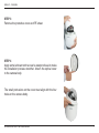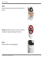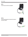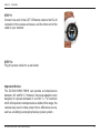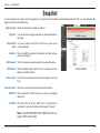
1
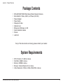
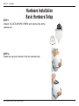
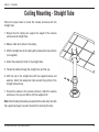
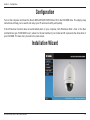
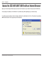
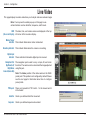
Table of Contents Table of Contents Product Overview......................................................... 3 Package Contents.................................................... 3 System Requirements.............................................. 3 Introduction............................................................... 4 Features................................................................... 4 Warnings.................................................................. 5 Hardware Installation................................................... 6 Basic Hardware Setup.............................................. 6 Resetting the Camera............................................. 12 Standard or Mini Pendant Mount............................ 13 Ceiling Mounting - Straight Tube............................ 14 Configuration.............................................................. 15 Installation Wizard.................................................. 15 Access the DCS-6815/6817/6818 with an Internet Browser.................................................................. 16 Live Video............................................................... 17 Internet Connection Setup Wizard.......................... 19 Motion Detection Setup Wizard.............................. 21 Dynamic DNS......................................................... 22 Color Setting........................................................... 23 Image Setup........................................................... 24 Motion Detection..................................................... 25 Time and Date........................................................ 26 D/I Setup (Digtal Input)........................................... 27 PTZ Setup.............................................................. 28 D-Link DCS-6815/6817/6818 User Manual General............................................................. 28 PTZ Sequence.................................................. 30 PTZ Auto Pan................................................... 31 PTZ Cruise........................................................ 32 PTZ Privacy Mask............................................. 33 Recording............................................................... 34 Snapshot................................................................ 35 Digital Output.......................................................... 36 PTZ Preset............................................................. 37 Device Management................................................... 38 Backup and Restore............................................... 39 Firmware Upgrade.................................................. 40 Device Info.................................................................. 41 DI/DO Pin Block Specifications................................. 42 Digital Input Diagram.............................................. 43 Digital Output Diagram........................................... 44 Troubleshooting......................................................... 45 Networking Basics..................................................... 47 Check your IP Address........................................... 47 Statically Assign an IP Address.............................. 48 Technical Specifications........................................... 49 2 Section 1 - Product Overview Product Overview Package Contents • • • • • • • • • • DCS-6815/6817/6818 High Speed Dome Network Camera Data Cable for Video, Alarm, and Power (AC 24V) Power Adapter Power Cable Waterproof Collar Optical Cover Manual and Software on CD Quick Installation Guide Screws Lubricant If any of the above items are missing, please contact your reseller. System Requirements • • • • • CPU: Pentium 4 1.4GHz or above Hard Disk: 40GB or above Memory: 256MB or above Browser: Internet Explorer 6.0 or above Video Resolution: SVGA or XGA (1024x768 or above) D-Link DCS-6815/6817/6818 User Manual 3 Section 1 - Product Overview Introduction The DCS-6815/6817/6818 High Speed High Speed Dome Network Camera is a professional IP surveillance solution which connect to your network to provide high-quality live video over the Internet. The camera apparatus supports precise high-speed pan/tilt/zoom functionality for extensive monitoring, and object tracking. The inconspicuous dome enclosure can be mounted in a variety of positions based on your needs. Features Real-time MPEG-4 / MJPEG Compression (Selectable) The IP speed Dome Camera supports two selectable compression formats (MPEG-4/MJPEG), but only one setting can be used at a time. Up to 30fps at D1 Resolution The IP speed Dome Camera supports up to 30fps (NTSC) or 25fps (PAL) at D1 resolution. Motion Detection Users can specify detection areas from a 3x3 grid and adjust the sensitivity to fit the operating environment. Supports Multiple Connections The IP speed Dome Camera allows multiple users to log in via the IE browser. Maximum 10 accounts can be set for one camera. Upgrade from Internet Users can upgrade to the latest software version via the Internet. D-Link DCS-6815/6817/6818 User Manual 4 Section 2 - Installation Warnings Handle the camera with care. Do not abuse the camera. Avoid striking, shaking, or otherwise disturbing the enclosure. Improper handling or storage may damage the camera. Install electrical wiring carefully. Consult a qualified electrician regarding camera installation. Please note that the camera’s electrical input tolerance is AC 24V ± 10%. Ensure that the AC adapter’s power cable is grounded appropriately to protect against power surges. Do not disassemble the camera. To prevent electric shock, do not remove screws or covers. Consult D-Link regarding service if necessary. Do not block the cooling holes on the bracket. This camera has a cooling fan inside. Blocking the cooling holes will lead to overheating and may cause damage. Do not operate the camera beyond the specified temperature, humidity or power source ratings. Use the camera under conditions where the temperature is between -40°C ~ 50°C (-40°F ~ 122°F), and relative humidity is below 80%. Do not use strong or abrasive detergents when cleaning the camera body. Use a dry cloth to clean the camera when it is dirty. A mild detergent can be used if necessary. Never aim the camera towards the sun. Never aim the camera at the sun or other extremely bright light sources, even when the camera is not in use. Doing so may cause damage to the camera’s sensors. D-Link DCS-6815/6817/6818 User Manual 5 Section 2 - Installation Hardware Installation Basic Hardware Setup STEP 1 Unpack the DCS-6815/6817/6818 and remove the dome camera unit. STEP 2 Rotate the cap and remove it from the camera body. D-Link DCS-6815/6817/6818 User Manual 6 Section 2 - Installation STEP 3 Remove the protective cover and PE sheet. STEP 4 Apply some lubricant on the cover’s waterproof seal to make the installation process smoother. Attach the optical cover to the camera body. The small protrusions on the cover must align with the four holes on the camera body. D-Link DCS-6815/6817/6818 User Manual 7 Section 2 - Installation STEP 5 Gently press down the dome cover with two hands on the side of it. Warning: DO NOT press down on the cover, as shown in the figure; this might cause damage to the camera. STEP 6 Screw the dome cover and body together. D-Link DCS-6815/6817/6818 User Manual 8 Section 2 - Installation STEP 7 Insert the data cable into the opening on the cap. STEP 8 Connect the 22-pin connector to the slot on the camera enclosure. The connector will lock into place. D-Link DCS-6815/6817/6818 User Manual 9 Section 2 - Installation STEP 9 Connect the power cable to the power adapter. STEP 10 Connect the power adapter's 3-pin connector to the camera's 3-pin power connector. D-Link DCS-6815/6817/6818 User Manual 10 Section 2 - Installation STEP 11 Connect one end of the CAT 5 Ethernet cable to the RJ-45 connector of the camera enclosure, and the other end of the cable to your network. STEP 12 Plug the power cable into a wall outlet. Important Notice: The DCS-6815/6817/6818 can operate at temperatures between -40° and 50° C. However, the power adapter is only designed to operate between 0° and 40° C. For locations which will experience temperatures outside of this range, the camera may need to draw power from a difference source, such as a building's emergency/backup power system. D-Link DCS-6815/6817/6818 User Manual 11 Section 2 - Installation Resetting the Camera The DCS-6815/6817/6818 contains both digital and mechanical components. Thus, if any problems are experienced with the camera, there are two different reset options depending on the type of problem. Mechanical Reset If the mechanical PTZ controls ever stop responding or seem to be locked up, you may reset the mechanical portion of the camera using the communication pin array at the base of the device. 1. Use a small tool to move switch 5 to the “off” position. 2. Plug the camera in for one minute and allow the device to initialize. 3. Return the pin back to its original “on” position. 4. Plug in the camera, and the device should successfully initialize. Digital Reset If the camera’s web user interface ever becomes unresponsive, or if the administrator password is forgotten, it may become necessary to reset the device firmware to its original factory settings. 1. Press and hold the green button on the base of the camera for 10 seconds. 2. Allow a few minutes for the camera to re-initialize factory default settings. D-Link DCS-6815/6817/6818 User Manual 12 Section 2 - Installation Standard or Mini Pendant Mount Follow the steps below to mount the camera enclosure with the pendant mount. 1. Make a cable entry hole on the wall to recess the cables. Alternatively, cables can be threaded through the cable entry hole on the mounting plate. Sponge 2. To prevent insects from entering the pendant mount, you may block the cable entry hole with the supplied sponge in two different ways. (See figures 1 and 2.) 3. Thread the cables through the pendant mount and affix the pendant mount on the wall with screws and screw anchors (not supplied). Figure 1 Sponge 4. Attach the waterproof collar to the pendant mount. 5. Thread the cables through the cap and affix it to the pendant mount with the supplied screws and washers. Figure 2 6. Connect the cables to the camera enclosure. Attach the camera enclosure to the mount and affix it with the supplied bolt. Note: After threading the cables, please block the cable entry hole with the supplied sponges to prevent insects from entering the tube. D-Link DCS-6815/6817/6818 User Manual 13 Section 2 - Installation Ceiling Mounting - Straight Tube Follow the steps below to mount the camera enclosure with the straight tube. 1. Ensure that the ceiling can support the weight of the camera enclosure and straight tube. 2. Make a cable entry hole on the ceiling. 3. Affix the straight tube to the ceiling with screws and screw anchors (not supplied). 4. Attach the waterproof collar to the straight tube. 5. Thread the cables through the straight tube and the cap. 6. Affix the cap to the straight tube with the supplied screws and washers. Attach the waterproof collar around the junction of the straight tube and cap. 7. Connect the cables to the camera enclosure. Attach the camera enclosure to the cap and affix it with the supplied bolt. Note: After threading the cables, please block the cable entry hole with the supplied sponges to prevent insects from entering the tube. D-Link DCS-6815/6817/6818 User Manual 14 Section 3 - Configuration Configuration Turn on the computer and Insert the D-Link DCS-6815/6817/6818 Driver CD in the CD-ROM drive. The step-by-step instructions will help you to search and setup your IP camera smoothly and quickly. If the CD Autorun function does not automatically start on your computer, click Windows® Start > Run. In the Run command box type “D:\DCS861#.exe”, where # is the last number of your model and D: represents the drive letter of your CD-ROM. If it does start, proceed to the next screen. Installation Wizard D-Link DCS-6815/6817/6818 User Manual 15 Section 3 - Configuration Access the DCS-6815/6817/6818 with an Internet Browser Open your Internet Explorer Web browser and enter the IP address for your Internet Camera (http://192.168.0.20). In the example, this address is 192.168.0.20. Your address may differ depending on your network setup. If a window appears asking to install a Verisign certificate for authentication click Yes. This allows the proprietary MPEG4 video stream to be recognized by Internet Explorer. D-Link DCS-6815/6817/6818 User Manual 16 Section 3 - Configuration Live Video This page displays live video and allows you to adjust and save camera images. Note: You may need to enable pop-ups on this page to use certain functions such as AutoPan, Sequence, and Presets. OSD: The date, time, and camera name are displayed at the top (On screen Display) left corner of the live video display. Motion Trigger Indicator: This indicator blinks when motion is detected. Recording Indicator: This indicator blinks when the camera is recording. Digital Input Indicator: These indicators blink when digital input is received. Navigation Pad: The navigation pad is used to carry out pan, tilt, and zoom (Up/Down/Left/ functions. The camera can be aimed and the image adjusted Right/Home using this pad. Zoom In/Zoom Out) Note: The Home position of the dome camera is the 256th preset point. This position is not configured by default. Please see the next page for information about how to configure preset points. PTZ Speed: There are 8 speeds for PTZ control - 1 is the slowest and 8 is the fastest. AutoPan: Starts a pre-defined AutoPan movement. Sequence: Starts a pre-defined sequence movement. D-Link DCS-6815/6817/6818 User Manual 17 Section 3 - Configuration Cruise: Starts a pre-defined cruise movement. Autofocus: Click this button to enable automatic focus. Set Preset: Move the camera to the desired view using the P/T/Z controls and click this button to create a preset point. Designate the preset with a number between 1 and 256. The 256th preset point corresponds to the Home position. Run Preset: Returns the camera to a specified preset point. Focus (-/+): Manually focuses the camera image. Language: You may select English or Traditional Chinese. Fullscreen: Loads the live camera image in fullscreen. Snapshot: Saves a snapshot of the image to the specified location. Start/Stop Begins recording to the specified location. Pressing this button Recording: a second time will stop the recording. Set Storage Designates a folder where snapshots and video will be Folder: saved. Start/Stop Digital Output: Sends a signal to the attached digital device. D-Link DCS-6815/6817/6818 User Manual 18 Section 3 - Configuration Internet Connection Setup Wizard You may choose to configure your network by using the Internet Connection Setup Wizard which includes step-by-step instructions. Otherwise, you may manually configure your connection using the Manual Internet Connection Setup. This wizard will guide you through a step-by-step process to configure your new DCS-6815/6817/6818 and connect it to the Internet. Click Next to proceed. Click Next You may configure your camera using: DHCP Connection (by default), where your DHCP server will automatically assign dynamic IP to your device. Static IP Address, where an IP address is assigned manually. PPPoE connection, where your camera is directly connected to the Internet through a DSL modem. Input the DNS information if you have chosen and assigned a Static IP Address for your camera. Click Next to proceed. Click Next D-Link DCS-6815/6817/6818 User Manual 19 Section 3 - Configuration If you have a Dynamic DNS account and would like the camera to update your IP address automatically, enable DDNS and enter your host information. Click Next to proceed. Click Next Enter a name for your camera. Then, click Next to proceed. Click Next Configure the correct time to ensure that all events are triggered, captured and scheduled at the right time. Then, click Next to proceed. Click Next This page displays your configured settings. Click Apply to save and activate the setting, or Back to change your settings. Click Apply D-Link DCS-6815/6817/6818 User Manual 20 Section 3 - Configuration Motion Detection Setup Wizard You may choose to configure your camera with the Motion Detection Setup Wizard which includes step-by-step instructions. Otherwise, you may manually configure your connection by using the Motion Detection option from the Setup menu. This wizard will guide you through a step-by-step process to configure motion detection settings. Please see page 26 for more information on these individual settings. D-Link DCS-6815/6817/6818 User Manual 21 Section 3 - Configuration Dynamic DNS Dynamic DNS allows you to use a domain name (for example, yourhost.dyndns.org) to access a camera which operates using a dynamic IP address. Most internet service suppliers only provide customers with a dynamic IP address. Enable: Select this box to enable DDNS functionality. Service Address: Use the drop-down menu to assign your dynamic DNS service. Host Name: Enter the host name of the DDNS server. Timeout: Set the timeout period the camera will wait between IP updates to the dynamic DNS server. Username: Enter the username for the DDNS host. Password: Enter the password or key for your DDNS account. Verify Password: Reenter the password or key for the DDNS account. D-Link DCS-6815/6817/6818 User Manual 22 Section 3 - Configuration Color Setting This section allows you to configure the color settings for your camera. Brightness: Adjust this control to compensate for brightly backlit camera images. Contrast: Adjust this control to increase/decrease the color contrast of the camera image. Saturation: Adjust this control to increase/decrease the color saturation of the picture. Hue: Adjust this control to change the overall color of the image. D-Link DCS-6815/6817/6818 User Manual 23 Section 3 - Configuration Image Setup Adjustments to these settings will affect the amount of network resources that the camera will use. Video Compression You may designate MPEG4 or MJPEG as the compression Type: type for the video stream. Resolution: You may enable this option to alter the resolution of the real-time video stream. The options include: NTSC: D1 (720x480), CIF (352x240), QCIF (176x120) PAL: D1 (720x576), CIF (352x288), QCIF (176x144) Bitrate Type: This setting can be used to assign an appropriate bitrate type for the camera. A lower bitrate uses fewer network resources, but produces a lower quality image. Frame Per Sec: This option controls the number of frames displayed per second for video streaming. GOP Size: Enable this option to adjust the smoothness of streaming video. The options include 1 * FPS and 2 * FPS. A larger number may produce a smoother picture. D-Link DCS-6815/6817/6818 User Manual 24 Section 3 - Configuration Motion Detection This section allows you to enable and configure motion detection areas. Enable: Select this checkbox to enable motion detection. Enable Type: You may choose to always use motion detection, or only on certain days at specific intervals. Schedule Days: For scheduled recording, you may choose which days of the week to record. Start Time: Select the time when the motion detection should begin. Stop Time: Select the time when the motion detection should stop. Detect Area: The viewing area is divided into nine numbered blocks. Click on a block to select it for motion detection. Areas designated for motion detection will appear in red. Sensitivity: Defines the basic sensitivity of the motion detection. Adjust this value first. Low values mean that minor motions lasting only a short time will not trigger the alarm. Acceptable values are between 1 and 100. D-Link DCS-6815/6817/6818 User Manual 25 Section 3 - Configuration Time and Date This section allows you to set the system time on the camera. Server Time: Displays the time on server as it is currently set. Time Zone: Select a time zone in accordance with the location of the camera. Client PC Time: Set the time and date based on your computer’s system time. Time Server: S e t t h e t i m e a n d d a t e a u t o m a t i c a l l y b a s e d on a Network Time Protocol Server (NTPS). The options include pool.ntp.org server and time.windows.com server. D-Link DCS-6815/6817/6818 User Manual 26 Section 3 - Configuration D/I Setup (Digtal Input) The camera provides eight alarm inputs and one alarm output to connect alarm devices. With this function, the camera can cooperate with alarm system to catch event images. No. # DI Type: Normal Open is for digital input that is activated when the circuit is closed. Normal Close is for digital input that is activated when the circuit is opened. For example: Connect the Alarm input terminal to ALM GND to activate [NC] or floating (unconnected) [NO] to deactivate D-Link DCS-6815/6817/6818 User Manual 27 Section 3 - Configuration PTZ Setup General This section contains general settings for pan, tilt, and zoom functions. Backlight: Select this box to enable backlight compensation. The backlight compensation function prevents the center object from appearing too dim when excessive light is behind an object. Once activated, the center object will be brighter relative to the edges of the picture where the backlight originates from. Digital Zoom: Select this box to enable digital zoom. The camera uses digital zoom once the maximum optical zoom level has been reached. WDR: Select this box to enable wide dynamic range. This setting improves images with heavily backlit subjects. AE Mode: Auto (Auto Exposure In this mode, the camera’s brightness, shutter speed, iris and AGC (auto gain control) control circuits work together Mode) automatically to achieve a consistent video output level. Shutter In this mode, shutter speed controls exposure. The iris and AGC will function automatically in cooperation with the shutter speed to achieve a consistent video output level. Iris In this mode, the iris function controls exposure. The shutter speed and AGC circuit will function automatically in cooperation with the iris to achieve a consistent video output level. AGC In this mode, the Automatic Gain Control circuit controls exposure. The shutter speed and iris will automatically function in cooperation with AGC to achieve a consistent video output level. D-Link DCS-6815/6817/6818 User Manual 28 Section 3 - Configuration WBC Mode: Auto In this mode, white balance works within its color temperature range. This mode computes the white balance value output using color information from the entire screen. Manual In this mode, users can change the white balance value manually. R gain and B gain are adjustable and range from 000 to 127. Flip: Two flip modes are available for adjusting the image when the camera tracks an object that passes directly beneath the dome. Image Flip (Digital) This mode will automatically adjust the image using software. Digital flip is generally acceptable for object tracking. However, some camera modes may be incompatible with this mode. M.E. Flip (Mechanical) This mode uses the pan/tilt mechanism to follow an object. Mechanical flip may be used in situations where digital flip is not possible. IR (Day/Night): Color This mode never uses the infrared function. Mono This mode displays only monochrome images captures using the infrared function. Auto Activate the infrared function whenever necessary (nighttime / low light). Set Home: The camera will resume the specified PTZ action after the specified idle period of no manual operation. D-Link DCS-6815/6817/6818 User Manual 29 Section 3 - Configuration PTZ Sequence The function executes pre-positioning of the pan, tilt, zoom, and focus features in a certain sequence for a camera. Before setting this function, users must define at least two preset points. Path: Up to 8 preset paths can be defined. Each path can contain up to 32 preset points. Select the button next to the path that you would like to set. Set Preset Point: Select a position from one of the 256 preset points for the sequence path and click Add, Delete, or Modify. Dwell Time: The number of seconds that the camera should remain at the specified preset point. Speed: The speed at which the camera should move between the specified presets. Delete/Modify: You may select a defined preset and delete or modify it. Note: All preset points must be valid to ensure proper operation. D-Link DCS-6815/6817/6818 User Manual 30 Section 3 - Configuration PTZ Auto Pan Auto Pan scans an area horizontally from left to right or right to left. Path: Up to 4 Auto Pan paths may be defined. Select the button next to the path that you would like to set. Use the navigation pad to move the camera view to the desired start point and click Set Start Point. Move the camera view to the desired end point and click Set End Point. Direction: Choose the direction that the camera should pan. Speed: Choose the speed at which the camera should pan. D-Link DCS-6815/6817/6818 User Manual 31 Section 3 - Configuration PTZ Cruise Cruise is a stored route defined through manual adjustment of pan, tilt, and zoom. Path: You may set up to 4 different PTZ cruise paths. Set Start: Press this button to specify the cruise starting point. Use the control panel to move the camera along the desired cruise route. Set End: Press this button once you are done setting the cruise path. Test: Pressing this button will display the cruise path that has been specified. Stop: Press stop to cancel the cruise path test. D-Link DCS-6815/6817/6818 User Manual 32 Section 3 - Configuration PTZ Privacy Mask The privacy mask function will block a defined area of the monitored video from view. The privacy mask will automatically adjust the masked area as the camera view is adjusted via PTZ functions. Creating a Privacy Mask 1. Select a color for the privacy mask and select the checkbox labeled Enable. The chosen color will be used for all masks that have been set. 2. Click Submit. 3. Ensure that the camera is zoomed out completely (1X magnification). 4. Use the camera controls to target the center of the image on the area that you would like to mask. 5. Specify which privacy mask you would like to set (1-16). 6. Set the H size (horizontal) and V size (vertical) then click Set Mask. 7. You may fine tune your settings if needed and click Set Mask again. Enable: Select this checkbox to enable the privacy mask. Mask Color: This is the color that will be displayed over the masked area. Mask Area Setting: Select which mask area you would like to set. You may set up to 16 different masked areas. H Size: Specifies the horizontal length of the masked area in pixels. V Size: Specifies the vertical length of the masked area in pixels. Set Mask: Click this button to set the mask area after specifying the settings. Clear Mask: Click this button to clear the selected mask. D-Link DCS-6815/6817/6818 User Manual 33 Section 3 - Configuration Recording This page allows you to adjust FTP server settings and event triggers. Enable: Select this checkbox to enable recording. Record to FTP Server: The camera can record video directly to an FTP server. FTP Server: This is the address of the SMTP server. You may enter an IP address or a DNS address. FTP Port: This is the port that the FTP server operates on. The default FTP port is 21. Login User: This is the username that will access the FTP server. Login Password: This is the password associated with the FTP username. Verify Password: Type the FTP password a second time for verification. Filename Prefix: This is the prefix that will be appended to the beginning of the file before the date. Save Path: This is the folder on the FTP server to which the recording will be saved. Trigger By: You may choose to trigger recording by motion detection or digital output. Pre-record Time: This is the amount of time that will be recorded prior to the event. Post-record Time: This is the amount of time that will be recorded after the event. D-Link DCS-6815/6817/6818 User Manual 34 Section 3 - Configuration Snapshot In order to enable your camera to take snapshots, you must select the checkbox marked Enable snapshot. Then, you can determine the trigger event(s) email notification(s). Enable Snapshot Select this checkbox to enable snapshots. Trigger By: You may choose to trigger snapshots by motion detection or D/I signal. Remote SMTP You must configure the SMTP server that you will use to Setup: e-mail snapshots. Auth User: This is the SMTP username. Sometimes, this field requires a full e-mail address. Auth Password: This is the password associated with the username above. SMTP Server: This is the address of the SMTP server. You may enter an IP address or a DNS address. Sender’s Email: This is the e-mail address that the mail will appear to be sent from. Recipient’s Email: This is the e-mail address that the mail will be sent to. SMTP Port: This is the SMTP port that the server runs on. The default value is 25. Test SMTP: Click this button to test the SMTP port. If a connection is operable, the system will display the message "Success." Note: The DCS-6815/DCS-6817/DCS-6818 do not support SSL mail servers. D-Link DCS-6815/6817/6818 User Manual 35 Section 3 - Configuration Digital Output Enable your D/O port as well as how the event will be triggered. Enable D/O Selecting this checkbox will enable a preset movement when Signal: motion is detected, or when input is received from a digital device. D-Link DCS-6815/6817/6818 User Manual 36 Section 3 - Configuration PTZ Preset Here you can enable a preset movement as well as how the event will be triggered. Enable Preset Selecting this checkbox will enable the first preset camera Movement: movement when motion is detected, or when input is received from a digital device. D-Link DCS-6815/6817/6818 User Manual 37 Section 3 - Configuration Device Management Change the administrator password or create an additional user account. Admin Password Enter the desired administrator password here. Type the Setting: password again to verify, and click Modify. Add User Account: Adds a new user account with the authority to view the video feed. The password must be entered twice for verification. User List: Displays a list of the of the configured users. You may select a user and click delete to remove them. Camera Name: This is the name that will appear in your network list. OSD Label: This is the name that will be overlaid on the camera image. Show OSD Label: Select this box to enable the name on the camera image. Show OSD Date: Select this box to enable the date on the camera image. Show OSD Time: Select this box to enable the date on the camera image. D-Link DCS-6815/6817/6818 User Manual 38 Section 3 - Configuration Backup and Restore This page contains the functions for backing up, restoring, and rebooting your camera. Save To Local Hard Press this button to save a backup of the current server Drive: settings to your hard drive. Note: The following items will not be backed up: 1. Auto Pan 2. Sequence 3. Cruise 4. Privacy Masks 5. Preset Points Load From Local Restores a previously saved backup of server settings. Hard Drive: Browse to the backup file and click “Load Configuration” to load the previously saved settings. Restore To Factory You may enable this option to restore to factory defaults. Be Defaults: advised that all previously saved settings will be erased. Reboot Device: You may click this button to reboot the camera. D-Link DCS-6815/6817/6818 User Manual 39 Section 3 - Configuration Firmware Upgrade The camera’s firmware version and date will be displayed on this page. You may go to the D-Link Support Page to check for the latest firmware versions available. To upgrade the firmware on your DCS-6815/6817/6818, please download and save the latest firmware version from the D-Link Support Page to your local hard drive. Locate the file on your local hard drive by using the Browse button. Then, open the file and click the “Upload” button to start the firmware upgrade. D-Link DCS-6815/6817/6818 User Manual 40 Section 3 - Configuration Device Info This section displays detailed information about your device and network settings. D-Link DCS-6815/6817/6818 User Manual 41 Section 3 - Configuration DI/DO Pin Block Specifications Pin 1 2 3 4 5 6 7 8 9 10 11 12 13 14 15 16 17 18 19 20 21 22 D-Link DCS-6815/6817/6818 User Manual Definition AC 24-1/DC (+) ALM NC AC 24-2/DC (–) ALM NO FG ALM COM Cable 20AWG 20AWG 20AWG 24AWG ISOG ALM-1 ALM-3 ALM-2 ALM-4 ALM-5 ALM-6 ALM-7 ALM-8 ALM GND VGND Video 24AWG 42 Section 3 - Configuration Digital Input Diagram Alarm Input: ALM-1 ~ 8 - ALM GND D-Link DCS-6815/6817/6818 User Manual 43 Section 3 - Configuration Digital Output Diagram Alarm Output: ALM NC / ALM NO – ALM COM (NC: normal close, NO: normal open) Max. load 3A, max. voltage 120V AC relay output. D-Link DCS-6815/6817/6818 User Manual 44 Section 5 - Troubleshooting Troubleshooting 1. What is the maximum number of users that can be allowed to access DCS-6815/6817/6818 simultaneously? The maximum number of users that can log onto the Internet Camera at the same time is 10. Please keep in mind the overall performance of the transmission speed will slow down when many users are logged on. 2. What algorithm is used to compress the digital image? The Internet Camera utilizes MPEG-4 Simple Profile Mode image compression technology to provide high quality images. 3. Can the Internet Camera be used outdoors? The DCS-6815/6817/6818 is IP66 certified and is weatherproof. Please use appropriate weatherproof cabling for safe installation. 4. When physically connecting the Internet Camera to a network what network cabling is required? The Internet Camera uses Category 5 UTP cable allowing 10 Base-T and 100 Base-T networking. 5. Can the DCS-6815/6817/6818 be connected to the network if it consists of only private IP addresses? Yes, the Internet Camera can be connected to a LAN with private IP addresses. 6. Why does the Internet Camera work locally but not externally? This might be caused by network firewall protection. The firewall may need to have some settings changed in order for the Internet Camera to be accessible outside your local LAN. Check with the Network Administrator for your network. Make sure that the Internet Camera isn’t conflicting with any Web server you may have running on your network. The default router setting might be a possible reason. Check that the configuration of the router settings allow the Internet Camera to be accessed outside your local LAN. D-Link DCS-6815/6817/6818 User Manual 45 Section 5 - Troubleshooting 7. Noisy images occur. How can I solve the problem? The video images might be noisy if the Internet Camera is used in a very low light environment. To solve this issue you need more lighting. D-Link DCS-6815/6817/6818 User Manual 46 Appendix B - Networking Basics Networking Basics Check your IP Address After you install your new D-Link adapter, by default, the TCP/IP settings should be set to obtain an IP address from a DHCP server (i.e. router) automatically. To verify your IP address, please follow the steps below. Click on Start > Run. In the run box type command and click OK. At the prompt, type ipconfig and press Enter. This will display the IP address, subnet mask, and the default gateway of your adapter. If the address is 0.0.0.0, check your adapter installation, security settings, and the settings on your router. Some firewall software programs may block a DHCP request on newly installed adapters. D-Link DCS-6815/6817/6818 User Manual 47 Appendix B - Networking Basics Statically Assign an IP Address If you are not using a DHCP capable gateway/router, or you need to assign a static IP address, please follow the steps below: Step 1 Windows® XP - Click on Start > Control Panel > Network Connections. Windows® 2000 - From the desktop, right-click My Network Places > Properties. Step 2 Right-click on the Local Area Connection which represents your D-Link network adapter and select Properties. Step 3 Highlight Internet Protocol (TCP/IP) and click Properties. Step 4 Click Use the following IP address and enter an IP address that is on the same subnet as your network or the LAN IP address on your router. Example: If the router´s LAN IP address is 192.168.0.1, make your IP address 192.168.0.X where X is a number between 2 and 99. Make sure that the number you choose is not in use on the network. Set Default Gateway the same as the LAN IP address of your router (192.168.0.1). Set Primary DNS the same as the LAN IP address of your router (192.168.0.1). The Secondary DNS is not needed or you may enter a DNS server from your ISP. Step 5 Click OK twice to save your settings. D-Link DCS-6815/6817/6818 User Manual 48 Appendix C - Technical Specifications Technical Specifications CAMERA SPECIFICATIONS 1/4” EX-View CCD Sensor Optical zoom DCS-6815: 18X Focal length 3.4~61.2 mm Angle of view (horizontal): 3.6° ~ 60.8° DCS-6817: 30X Focal length 3.4~102 mm Angle of view (horizontal): 2.2° ~ 60.8° DCS-6818: 36X Focal length 3.4~122.4 mm Angle of view (horizontal): 1.8° ~ 60.8° 12 Digital Zoom Day / Night: ICR 0.1 Lux (Color); 0.01 Lux (B/W) 540 TVL Electronic shutter speed 1/1 ~ 1/10K sec Auto Gain Control(AGC) Manual / Auto Focus(AF) Manual / Auto Exposure(AE) Manual / Auto While Balance(AWB) Backlight Compensation(BLC) Wide Dynamic Range (WDR) VIDEO CODEC SUPPORT JPEG for still image MPEG4/MJPEG dual format compression VIDEO RESOLUTION NTSC Support: Up to 30 fps at 176 x 120 Up to 30 fps at 352 x 240 Up to 30 fps at 720 x 480 PAL Support: D-Link DCS-6815/6817/6818 User Manual Up to 25 fps at 176 x 144 Up to 25 fps at 352 x 288 Up to 25 fps at 720 x 576 VIDEO FEATURES Adjustable image size and quality Time stamp and text overlays Configurable motion detection windows VIDEO BIT RATE Up to 3 Mbps NETWORK PROTOCOL SUPPORT IPv4, ARP, TCP/ IP, UDP, ICMP, DHCP Client, NTP Client, DNS Client, DDNS Client, SMTP Client, FTP Client, HTTP Server, PPPoE, UPnP BUILT-IN NETWORK INTERFACES 10/100BASE-TX Ethernet port LAN IEEE 802.3 compliance IEEE 802.3u compliance Full-Duplex operation 802.3x Flow control support for full-duplex mode IO Port 8 Alarm inputs 1 Alarm outputs DOME OPERATION 360° pan capability -10° ~ 190° Tilt travel 0.225° Pan / Tilt preset accuracy 5° ~ 400° Pan / Tilt preset speed 49 Appendix C - Technical Specifications 4 Cruise presets 4 Auto pan presets 8 Sequence presets 16 Privacy masks Auto-flip Built-in heater and fan IP66 standard SURVEILLANCE SOFTWARE FUNCTIONS Remote management/control of up to 32 cameras Viewing of up to 32 cameras on one screen Management functions provided in web interface Scheduled motion triggered, or manual recording STORAGE TEMPERATURE -20° to 70° C (-4° to 158° F) OPERATING HUMIDITY 20% to 80% non-condensing CERTIFICATIONS FCC CE RoHS REMOTE MANAGEMENT Configuration accessible via web browser Take snapshots/video clips and save via web browser SYSTEM REQUIREMENTS Operating System: Microsoft Windows 2000, XP, Vista Browser: Internet Explorer 6.0 or above WEIGHT 2.6 Kg (5.9 lbs) POWER INPUT AC 24 V POWER CONSUMPTION Max 65 W (with heater) OPERATING TEMPERATURE -40° to 50° C (-40° to 122° F) Version 1.1 3/15/2010 D-Link DCS-6815/6817/6818 User Manual 50