1
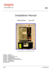
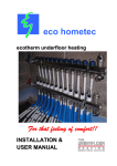
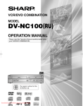
eco hometec
Variable Controlled Output
(VCO) Solar Compatible jjjjj
Gas Condensing Boilers
EC 25 COMPACT
TECHNICAL
MANUAL
eco hometec
Unit 11E
Carcroft Enterprise Park
Carcroft
Doncaster
DN6 8DD
Tel. 01302 722266
Fax. 01302 728634
e.mail. [email protected]
http://www.eco-hometec.co.uk
C:\amanuals\EC25CompactTechnicalManual021099.doc\30 June 2002
eco hometec has a policy of continuous improvement and reserves the right to change any
specification without notice. Your statutory rights are not affected.
eco hometec is committed to design, develop and produce environmentally friendly appliances
for both domestic and commercial applications
Page 2 ECO HOMETEC (UK) LTD.
Contents
1. Why choose eco hometec?............ 4
1.1 Benefits at a glance .........................4
2.
Introduction .................................... 5
2.1 The Condensing Process.................5
3.
Not all boilers are the same ........... 6
3.1
3.2
3.3
3.4
3.5
3.6
3.7
4.
How does VCO work?......................6
Approvals .........................................7
Modulating pump .............................7
Frost Protection................................7
Year Long Protection .......................7
P.P.S Plastic Flue System. ..............7
Additional Features ..........................8
Description of Appliances .............. 8
4.1 EC 25 H Compact ............................8
4.2 EC 25HS Compact...........................8
4.3 EC EC 25S Compact .......................8
5. Technical Information................... 10
6.
Accessories ................................. 14
7.
Hydraulic Connections ................ 15
7.1 First Fixing Pipe-work ....................15
7.2 Connections ...................................15
8. Flues and Ventilation ................... 17
8.1
8.2
8.3
8.4
8.5
8.6
Maximum Flue Lengths..................17
Available Flue Components ...........17
Vertical flue Installations ................18
Modular installations ......................18
Condensate Drain ..........................20
System By-Pass.............................20
9. Electrical Connections ................. 20
10. Heating Control Options............... 20
11. Additional Features ...................... 21
11.1
11.2
11.3
Laptop Serial Connection........... 21
8.1.5 Frost protection ................. 21
Weather compensation .............. 21
12. Hot water output .......................... 22
12.1
12.2
12.3
Combi Type ’S’ Tap boiler.......... 22
Pump operation.......................... 22
Hot Water Cylinder..................... 22
13. Safety devices ............................. 22
13.1
13.2
13.3
Flow protection........................... 22
High temperature protection ...... 23
Static pressure ........................... 23
14. Condensing System Design......... 24
14.1
14.2
14.3
14.4
14.5
Design Considerations............... 24
Traditional .................................. 24
Condensing................................ 24
Under-floor................................. 24
Under-floor Heating.................... 24
15. Under-floor heating ...................... 24
15.1
15.2
15.3
15.4
Systems using radiators............. 24
Sizing Radiators and Output ...... 25
Pipe Sizing and Flow Rates ....... 25
Control of Circuits ...................... 25
Figure 1 Solar heating................................ 9
Figure 2 Component Locations ................ 12
Figure 3 Pipework Connections ............... 15
Figure 4 Overall Dimensions .................... 16
Figure 5 Vertical Wall Terminal ................ 18
Figure 6 Vertical Flue Application ............ 18
Figure 7 Modular Installation.................... 18
Figure 8 Vertical Roof Terminals............. 19
Figure 9 Concentric flue fittings................ 19
Figure 10 80mm Flue Tubes .................. 20
Figure 11 Controls Terminal ................... 21
Figure 12 Control Terminal Block ........... 21
EC 25 Compact Technical Manual page 3
1.
Why choose eco hometec?
1.1 Benefits at a glance
Wall mounted ultra high efficiency gas boilers
Suitable for installation into existing systems, new radiator and/or
underfloor installations, can also be used with solar heating systems
A dramatic reduction of the harmful emissions NOx 8.1 – 27.1 ppm
and CO 2.9 – 66ppm.
Long life Austenitic stainless steel heat exchanger
Energy saving modulating fan
Energy saving modulating burner
Energy saving modulating pump
Energy saving modulating system water temperature
Corrosion free PPS plastic flue tubes and fittings offering ease of
siting
Data logging via PC for analysing, performance, operating times,
temperatures and for fine-tuning
Built in digital Weather Compensating comfort controller
HS specification with dual flow temperatures for under floor heating
systems
One of the most complete energy efficient home heating appliance
available
Guarantee periods Heat Exchanger 5 years other components 2
years
Free help with technical, design and installation issues
Page 4 ECO HOMETEC (UK) LTD.
2.
Introduction
One of the elements in both Natural Gas
and Propane is hydrogen. A gas burning
appliance mixes the gas with air and during
the combustion process hydrogen and
oxygen combine together and produce heat
(143,100kJ/kg) and water vapour (H2O).
For every kg of hydrogen burned 9kg of
water vapour is produced.
The
temperature in the heat exchanger of a
boiler can reach 14000C. The water vapour
produced is so hot it turns into superheated
steam.
2.1 The Condensing Process
This superheated steam contains both
sensible (available heat) and latent heat
(heat locked up in the flue gases). A
conventional boiler will recover some of the
sensible heat by passing these hot gases
over a heat exchanger.
The heat exchanger in non-condensing
boilers is generally made of cast iron and
cools the gases to between 2500C and
3500C.
A conventional boiler does not
recover any of the latent heat and this
energy is simply lost to the atmosphere
through a metal flue. These flue gases are
extremely hot and the lost energy wasted
can equate to up to half of the annual
running costs.
To sum up, with water return temperature of
550C or less, the latent heat is condensed
out of the flue gases.
A typical, non-condensing, central heating
system is designed with a water flow
temperature of 800C and a return water
differential of 100C. This design differential
is critical.
System designs had to incorporate high
return temperatures (typically 700C) to stop
any unwanted condensing of the flue gases.
The flue gases leaving a conventional boiler
have to be discharged very hot for the
following reasons.
To propel the flue gases up a chimney or
through a flue they have to be discharged
hot to give them buoyancy and enough
thermal lift to overcome the flues natural
resistance.
If the flue gases are not hot enough the
effectiveness of the flue system is reduced
and harmful by products of combustion
could enter the building via the appliance or
its flue.
A conventional boiler has to discharge the
flue gases hot to prevent any unwanted
condensing. If the flue gases are not kept
hot enough they will condense allowing
water to run back down the flue and into the
boiler.
A simple condensing boiler will however
extract more of the sensible heat and some
of the latent heat by cooling the flue gases
down to below 1000C.
Clearly this has to be avoided. Heat
exchangers made of cast iron, or boiler
designs not equipped to discharge this
water would suffer imminent failure.
When a condensing boiler is operating in its
most efficient manner flue gas temperatures
of around 500C will be achieved and the
boiler will now start to condense the flue
gases. The superheated steam is cooled to
its dew point, typically around 550C the flue
gases give up their latent heat to the boiler
and condense out.
The flue gas discharge from conventional
boilers has to be maintained at high
temperatures.
The critical factor that ensures maximum
efficiency from a condensing boiler is the
water return temperature. The water return
temperature determines whether the boiler
operates in condensing mode, which in turn
controls the boilers efficiency.
Questions you might be asking yourself now
might include:
Why were such inefficient
Question?
appliances designed?
Fossil fuels were
Answer:
cheap
and
the
environmental
consequences of burning and wasting so
much fuel were not fully appreciated.
EC 25 Compact Technical Manual page 5
Does an eco hometec boiler
Question?
need to maintain hot flue gas temperatures?
Answer:
No, eco hometec
boilers and flue systems are designed and
constructed from stainless steel and PPS
plastic.
The condensate water from
condensing flue gases does not affect these
materials.
What are the advantages of
Question?
such a design?
Answer:
Unlike conventional
boilers eco hometec appliances do not need
to waste gas in maintaining high flue gas
temperatures.
What does that mean in real
Question?
terms?
By
design
eco
Answer:
hometec boilers use less gas. They are a lot
more efficient than other boilers and will
significantly reduce your annual heating
costs.
Why should I choose an
Question?
eco hometec boiler?
Answer:
Heating our homes
and water for showers and baths is very
costly and bills in the future will only get
bigger. By choosing eco hometec for your
next boiler you can rest assured you have
chosen
the
most
economical
and
environmentally friendly boiler available.
Finally,
Question?
environment?
what
about
the
Answer: All eco hometec boilers use less
gas and the emissions from the EC25 range
are NOx 8.1 – 27.1 ppm and CO 2.9 –
66ppm.
efficient boiler. Typical efficiencies of 86%
are achievable when fitted to an existing
system with an 80/700C design.
But, by lowering the water return
temperature, condensing boilers are
capable of achieving efficiencies up to 98%.
How then can we lower the return water
temperature of our heating, increase
efficiency and at the same time save gas?
The eco hometec answer Variable
Controlled output (VCO)
To achieve optimum efficiency from a
condensing boiler we need to control the
temperature of the water returning to the
boiler.
This can best be achieved by adjusting the
output of the boiler and/or the pump speed.
The outside air temperature generally
determines the load on a heating system.
In the U.K we size a boiler to provide
enough heat to keep a house or building
warm at -10C.
As the outside air temperature rises then
less heat is required to heat the building.
If we were using gas fires to heat our home
then as the building warmed up we would
turn down the gas fire.
This has the
desired effect of lowering their output and at
the same time reducing gas consumption.
If we are using a central heating boiler to
heat our home then in an ideal installation,
as outside air temperature rise, we would
turn the boiler down to lower its output at
the same time reducing gas consumption.
The only problem was, until now, the output
of a gas boiler was determined by the set up
of the gas valve and only the service
engineer could carry out adjustments.
As you can now see there really is no
reason at all for choosing a boiler
constructed to an old and inefficient design
that needs to maintain high flue gas
temperatures.
Until eco hometec developed Variable
Controlled Output it was simply not possible
to constantly adjust a boilers output and
flow temperature to cope with changing
weather conditions.
3.
3.1 How does VCO work?
Not all boilers are the same
When deciding on a condensing boiler, we
know that as a result of their superior heat
exchanger design, we are getting a more
Page 6 ECO HOMETEC (UK) LTD.
Unlike most boilers with a constant input
and output eco hometec boilers incorporate
an integral compensating and modulating
digital controller that automatically adjusts
the boilers output depending on system
load requirements.
This feature, Variable Controlled Output
(V.C.O.), is the very latest from eco
hometec in condensing technology and
ensures the boiler maintains optimum
efficiencies even when operating at part
load.
A key component of VCO is the ECONOX
premixing, radiant, gas burner.
A unique feature of the ECONOX burner is
its radiation cylinder that has been specially
designed to suit the geometry of the
combustion chamber. It is composed of a
perforated sheet of stainless steel. On the
surface of this burner, accurate quantities of
premixed gas and air are burnt almost
without a visible flame
The eco hometec on-board computerised
VCO system with integral fault diagnostic
facility ensures that optimum efficiency is
maintained when operating in both heating
and domestic hot water modes.
According to the required flow temperature,
the premixing burner modulates constantly.
To save electricity, a 310Volt DC, high
efficiency fan is used with a variable speed
and power capacity; if the heat demand
decreases, the fan will turn at a lower
speed, which results in a lower power
consumption.
The air fan is programmed to supply given
amounts of air for specific burner outputs.
This air pressure then controls the gas
valve, which in turn matches the gas
pressure to the required gas to air ratio
(1:1).
The combustion gases are then passed
through the stainless steel heat exchanger
to the atmosphere. During their passage
these hot gases are used to preheat both
the return water to the boiler and the
incoming combustion air thus ensuring that
all of the available energy is used as
efficiently as possible.
3.2 Approvals
The unit has been approved according to
the European standards (CE).
3.3 Modulating pump
A modulating integral circulating pump is
supplied, which operates at to different
speeds and results in lower power
consumption.
This feature is to help maintain a
temperature difference of 20OC between the
flow and return temperatures on systems
using radiators.
IMPORTANT. Without VCO (Variable
Controlled Output) or an alternative control
over the temperature of the return water, the
performance of a condensing boiler will be
impaired and significantly lower.
A modulating pump is essential in all
condensing
systems
if
system
differentials are to be maintained.
3.4 Frost Protection
If the flow temperature falls below 80C, in
order to provide frost protection, the pump
will run even though there may be no
demand for heat. If the temperature
continues to fall, at 50C, the burner will also
ignite. At 100C the appliance will return to
standby mode.
3.5 Year Long Protection
During summer months, the pump and
mixer valve (if fitted) are exercised daily.
This
prevents
seizure
of
internal
components thus reducing maintenance
costs.
3.6 P.P.S Plastic Flue System.
Due to the extremely low temperature flue
gases, the boiler may be flued using the
lightweight and corrosion resistant eco
hometec P.P.S. plastic flue system. The
boiler can be flued over distances
previously impossible (up to 100 metres
depending on output and flue design) from
conventional boilers.
EC 25 Compact Technical Manual page 7
3.7 Additional Features
A unique and patented corrosion resistant
stainless steel condensate heat exchanger.
Integral sensors (NTC) for monitoring flow
and return water temperatures.
3 way switching valve and facilities for
connection to an eco hometec DHW storage
module or similar.
Computer controlled combustion analysis
with built in fault diagnosis facility. These
readings can be down loaded onto a PC by
using the interface cable and software
available from eco hometec.
4.
Description of Appliances
4.1 EC 25 H Compact
The ‘H’ model is suitable for a central
heating system with hot water and heating
circuit(s) controlled using two or more zone
valves.
The appliance produces a low temperature
output for under-floor heating or a
fixed/variable temperature output for
connection to radiators. Flow temperature
to hot water cylinder can be set as required
(max. 85OC)
Hot water cylinders must be double feed
indirect and to aid efficiency and fast
recovery times (all appliances are hot water
priority) should be of the high recovery type.
Recommended minimum coil capacity
25kW.
The unit has a variable capacity of 32 to
100%, while the maximum capacity can be
set and adapted to the capacity of the CH
system.
4.2 EC 25HS Compact
The ‘HS’ range are higher specification.
With its 4 x 15mm connections it offers a
low temperature output, typically 55OC, for
under-floor heating or a fixed/variable
Page 8 ECO HOMETEC (UK) LTD.
temperature
radiators.
output
for
connection
to
Despite the low boiler flow
temperatures feature ALL low temperature
under floor installations require an
obligatory mixing valve or high temperature
cut out thermostat installing as part of the
system controls.
Flow temperature to hot water cylinder can
be set as required (max. 85OC)
The unit has a variable capacity of 32 to
100%, while the maximum capacity can be
set and adapted to the capacity of the CH
system.
Hot water cylinders must be double feed
indirect and to aid efficiency and fast
recovery times (all appliances are hot water
priority) should be of the high recovery type.
Recommended minimum coil capacity
25kW.
4.3 EC EC 25S Compact
This unit has a built-in heat primary heat
exchanger and hot water production is
continuous.
The unit has a variable capacity of 32 to
100%, while the maximum capacity can be
set and adapted to the capacity of the CH
system.
The S (combi) range of eco
hometec boilers are all solar compatible and
can be installed directly as part of a solar
heating and hot water system. If you would
like more information on the eco hometec
solar heating systems and equipment
please call or e.mail or sales department.
All appliances are designed for sealed
system installation only and require a
suitably sized expansion vessel fitting to the
system.
Figure 1
Solar heating
EC25 ‘S’ Type Combi Hydraulic system design when installed with solar heating
EC 25 Compact Technical Manual page 9
5.
Technical Information.
Table 1
Dimensions & Connections
CE ~ 0063 AT3070
Product Identification Number
600mm x 360mm x 300mm
Dimensions (H x W x D)
Heating Circuit Connections
15mm
Gas Connection
15mm
Condense Drain Connection
15mm
Air Supply/Flue Connections
60mm-60mm (eccentric) 125/80mm (concentric)
Table 2
Heating Specifications
EC25
Models H, HS and S
Nominal Input To Heating
kW
7.2 – 24.5
Maximum Rated Input (S Type combi only)
kW
28
Nominal Output To Heating 80/600C
kW
7.1 – 24.2
Nominal Output To Heating 50/300C
kW
7.9 – 25.9
CO2 %
8.2 – 8.8%
0
0C
52
Flue Gas Temp @ 80/600C (Amb 200C)
0
0C
<70oC
* Maximum Flue Resistance
Pa
185
pH value of condensate water
PH
4-5.5
Maximum Flow Temperature
0
0C
90
Min/Max filling pressure
bar
1.0 - 3.0
Efficiency @ 80/60 C
%
91.0 – 89.0 % (partial load – full load)
Efficiency @ 50/300C
%
98.0 – 95.1 % (partial load – full load)
**Efficiency @ 50/300C
%
109 – 106.1% (partial load – full load)
Hot water efficiency in accordance with
CW-test measured over 24 hours
%
85
EPC
%
95.1
CO2 % content at min/max load
Dew Point of Flue Gases
0
* At this resistance, the load will remain within the limits indicated on the data plate.
**
European calculation methods are based on efficiency of 100% in units that do not
condense the flue gases, and of 110% in condensing units.
Table 3
Capacities & Weights
EC25
Model
Heating Water Capacity
litres
1.5
Heating Water Coil Capacity (S models)
Litres
3.1
Kg
35
Weight (empty)
Page 10 ECO HOMETEC (UK) LTD.
Table 4
Hot Water Specifications
EC25S
Model
Maximum Rated Input
kW
28
Modulating Output EC25
kW
8-28
Modulating Output EC18
kW
5-18
L/min
13
bar
8
Hot Water Flow (EC25 only) rates at
∆τ 30K (S type)
Maximum Tap Water Pressure
Table 5
Connection Values
mbar
Min/Max Gas Pressure
20/25
m/h
3
2.58
Maximum Input Rate Natural Gas (S Types)
m/h
3
2.95
Electrical Supply
VAC
230
Power Consumption Average
W
85
Thermostat Voltage
V
24
Maximum Input Rate Natural Gas (H & HS Types)
Table 6
Emission Values
CO2
natural gas: 8.2 – 8.8 %
CO (0 % O2)
natural gas: 2.9 – 66 ppm
NOx (0 % O2)
natural gas: 8.1 – 27.1 ppm
Noise Levels Pump high speed
50 dB(A)
Noise Levels Pump low speed
34 dB(A)
EC 25 Compact Technical Manual page 11
Figure 2 Component Locations
Page 12 ECO HOMETEC (UK) LTD.
Table 7
Pos.
Component List
Description
1
Heat exchanger
2
Hot tap water boiler
3
Pump
4
Three-way valve
5
Three-way valve internal parts
6
Incandescent igniter
7
Ionization pin
8
Burner
9
Condensation tray
10
Gas valve
11
Fan
12
Venturi tube
13
Water pressure sensor
14
Supply sensor
15
Return sensor
16
Safety device
17
Bleed valve
18
Hot water sensor
19
Exhaust gas sensor
20
Type plate
21
Condensation drain/high pressure protection
22
Gas
23
Central Heating Return
24
Central Heating Flow
25
Hot water outlet
26
Cold water inlet
27
Flow to Hot Water Cylinder
28
Return from Hot Water Cylinder
EC 25 Compact Technical Manual page 13
6.
Accessories
The following items are also available from eco hometec at extra cost.
Colour coded 1/4 Turn Isolating Valves.
Stainless Steel Flexible Pipe Connections.
In line Filter/Strainers.
Condensate sump pump for below ground installations.
installed below ground level.
N.B. LPG installations must not be
eco hometec servicing software and interface cable for connection to a PC.
For more details please contact the eco hometec technical department.
Table 8
All Types
X
X
X
X
X
Extra Items and accessories
All Types
X
X
X
X
X
X
All Types
X
X
X
X
X
Description
Concentric adapter
Connections Cover
Frame and cover with expansion tank
Mounting frame with expansion tank (NL)
External temperature sensor
Hot Water Cylinder sensor
eco hometec comprehensive range of PPS flue kits, fittings and accessories.
information please see section on flues
Page 14 ECO HOMETEC (UK) LTD.
For more
Figure 3
7.
Pipework Connections
Hydraulic Connections
7.1 First Fixing Pipe-work
All the pipe-work and wiring connections enter at the bottom of the unit. To ensure a tidy
installation it is important to consider at the first fixing stage the order you arrange the pipe-work
and if applicable any cable trunking. Figure 3 shows the order in which to fix the pipe-work.
7.2 Connections
1. Gas
2. Heating Return
3. Heating Flow
4. Flow Domestic Hot Water
5. Cold Mains Water
6. Flow to Hot Water Cylinder
7. Return from Hot Water Cylinder
EC 25 Compact Technical Manual page 15
Figure 4 Overall Dimensions
Page 16 ECO HOMETEC (UK) LTD.
8.
Flues and Ventilation
It is advisable when installing the boiler to
use an eco hometec P.P.S. plastic
concentric flue system or the twin 60mm
tube system. This not only ensures that
there is sufficient combustion air, but also
reduces room ventilation requirements thus
increasing the number of possible suitable
locations.
The internal boiler flue system is
manufactured in stainless steel and the flue
outlet is designed to be connected to an
external P.P.S plastic flue system.
8.1 Maximum Flue Lengths
The flue materials, flue insulation, the
amount of vertical and horizontal pipe and
the amount of bends incorporated
determine the maximum permissible flue
length. The excess fan pressure available
for overcoming the frictional resistance of
the flue system is 100 p.a.
8.2 Available Flue Components
80/125 Concentric 500 mm Fanned Flue Kit
80/125 PPS/White Galvanised 90 degree elbow
80/125 PPS/White Galvanised 45 degree elbow
80/125 1000mm length PPS/White Galvanised Concentric Flue
80/125 500mm length PPS/White Galvanised Concentric Flue
80mm 1000mm PPS flue pipe
80mm PPS 45 degree PPS Elbow
80mm PPS 45 degree connector
80/125 Roof Terminal, Pitched roof tile flashing, Aluminium flat roof flashing.
80mm Wall Fixing Clamp + 125mm Wall Fixing Clamp
80mm PPS flexible flue liner (per metre)
80mm PPS flexible flue liner 360-degree spacers
80mm PPS flexible flue liner chimney terminal
80mm PPS flexible flue liner chimney terminal clamp
80mm PPS flexible flue liner boiler flue connector
A range of 60mm PPS bends, tubes and connectors
60mm Grey PPS 45 degree bend
60mm Grey PPS 90 degree bend
60mm x 500mm length PPS/Grey Flue Tube
60mm x 1000mm length PPS/Grey Flue Tube
60mm x 2000mm length PPS/Grey Flue Tube
60mm Inspection point
60mm Tee Piece
60mm Wall Bracket
60mm Wall Terminal Kit (2 wall plates and S/Steel Grid)
EC 25 Compact Technical Manual page 17
Figure 5
Vertical Wall Terminal
8.4 Modular installations
For multiple boiler (modular) installations
eco hometec supply a range of larger
diameter flues.
Sizes are available in 150mm, 200mm and
250mm. For assistance in flue design and
specification please call the eco hometec
technical department.
Figure 7
8.3 Vertical flue Installations
For vertical flue applications a range of
fittings for both pitched and flat roofs are
available. Please contact eco hometec for
further advice.
Figure 6
Vertical Flue Application
Page 18 ECO HOMETEC (UK) LTD.
Modular Installation.
Figure 8
Vertical Roof Terminals
Concentric vertical flue fittings are available
from eco hometec.
Figure 9
Concentric flue fittings
Concentric flue components have push
together spigot and socket joints.
The
inner PPS flue gas tube has silicone seal
rings located in the socket component. The
outer air tube has EPDM rubber seal rings
located in the socket component.
To aid
assembly and assurance that the joints
have been fully pushed home, the seal rings
and make ends of tubes and fittings should
be lightly lubricated with silicone grease.
Additional 80/125mm concentric flues tubes
and fittings are available from eco hometec
details below:
80/125
1000mm
length
Galvanised Concentric Flue
80/125
500mm length
Galvanised Concentric Flue
80/125 PPS/White Galvanised
elbow
80/125 PPS/White Galvanised
elbow
125mm Wall Fixing Clamp
PPS/White
PPS/White
90 degree
45 degree
EC 25 Compact Technical Manual page 19
Additional 80 PPS flues tubes and fittings
are available from eco hometec details
below:
Figure 10 80mm Flue Tubes
8.5 Condensate Drain
The condense discharge pipe should
be continued in ¾ inch plastic waste pipe
into the household drainage system or out
through the wall to an existing gully or soak
away. To minimise the risk of freezing all
condensate
waste
pipe-work
fitted
externally should be 32mm. (The existing
drainage system should be corrosion
resistant).
8.6 System By-Pass
The boiler is designed to operate at a
minimum flow rate. If zone valves are fitted
to all the heating circuits then an adequate
bypass (Honeywell DU 145 suggested)
should be installed across the flow and
return so that it is the first flow after the
pump and the last return to the boiler.
Please contact eco hometec Technical
Department for more information if required.
9.
Electrical Connections
Using the 3 core cable supplied connect the
boiler to the mains electrical supply.
80mm 1000mm PPS flue pipe
80mm PPS 45 degree PPS Elbow
80mm PPS 45 degree connector
80mm Wall Fixing Clamp
80mm – 100mm increaser
Above also available in 60mm
A range of Flexible Flue liners are also
available details below.
80mm PPS flexible flue liner (metre)
80mm PPS flexible flue liner 360-degree
spacers
80mm PPS flexible flue liner chimney
terminal
80mm PPS flexible flue liner chimney
terminal clamp
80mm PPS flexible flue liner boiler flue
connector
For the proper functioning of the appliance,
it is necessary that live and neutral be
correctly connected.
Check the status
code on the display if the display shows a
U, you must reverse the connections to the
mains plug in the power supply socket.
10.
Heating Control Options
The low voltage terminal strip can be used
to connect the following.
Hot water cylinder sensor.
External temperature sensor.
Room thermostat.
All of the above are available from
eco hometec
Page 20 ECO HOMETEC (UK) LTD.
Figure 11 Controls Terminal
11.
Additional Features
11.1
Laptop Serial Connection
For an extended diagnosis and display of
functions, a PC or laptop computer can be
connected to connector (3) (Fig. 13). The
required connecting cable and software is
available from eco hometec as an option.
11.2
The boiler control inputs are all low voltage
and must no be connected directly to the
mains.
The connection terminal block plug (fig. 18)
is located underneath the boiler see fig 19.
Figure 12 Control Terminal Block
8.1.5 Frost protection
If the temperature detected by the supply
sensor falls below 8 °C, the pump will be
switched on and will circulate water through
the central heating circuit. If the temperature
detected by the supply sensor falls below
3 °C, the burner will be ignited. As soon as
the return temperature reaches 15 °C, the
burner will be switched off. The pump will
continue to run for the pre-set overrun time.
It is also possible to set the pump to run
continuously.
11.3
Weather compensation
This function is only available if the optional
external sensor is connected. The external
temperature
control
determines
the
optimum set value of the central heating
temperature in relation to the prevailing
external temperature.
1
2
3
4
5
EC 25 Compact Technical Manual page 21
12.
Hot water output
Pressure difference < 0.06 bar:
12.1
Combi Type ’S’ Tap boiler
1.
Air in the appliance
Pump or pump connection is broken. The
control system switches to the pump test
phase, in which the pump is switched on for
30 seconds and then off for 30 seconds.
During this test phase the control system
waits until a sufficient pressure difference is
created. The display shows ‘P’ continuously
and all heating demands are disregarded.
The appliance is provided with an integral
hot water store that keeps a limited quantity
of hot water at a pre-set temperature.
This means that hot water is always
available. As soon as the temperature in
the tap boiler falls below 5 °C below set
point the burner ignites and functions on low
load.
12.2
Pump operation
The pump has two speeds: low (1750 rpm)
and high (2200 rpm). Normally the pump
runs at low speed. When a value for ∆t of
30 °C is reached, the pump switches to high
speed. Only when ∆t is smaller than 10 °C
does the pump switch back to low speed.
When the heating demand is removed, the
pump continues to run for the pre-set
overrun time, at the end of which it is
switched off.
12.3
Hot Water Cylinder
A hot water cylinder boiler can be directly
connected to the EC25HS. The cylinder
temperature can be regulated by means of
a thermostat or an NTC temperature
sensor. When an NTC-sensor is used, the
appliance will modulate during the boiler
heating cycle. In the following process
description it is assumed that regulation
takes place by means of an NTC-sensor.
13.
Safety devices
13.1
Flow protection
The appliance is provided with a water
pressure sensor that is used in combination
with the supply and return sensors to
protect the appliance.
For every burner start, the pump is stopped
and after a 2 second delay the static system
pressure is measured. Hereafter the pump
is restarted at high speed. The fan runs and
the pre-ignition phase begins.
At the end of the pre-ignition phase the
system pressure is measured again.
The following situations are possible:
Page 22 ECO HOMETEC (UK) LTD.
Pressure difference > 0.44 bar:
Too little flow. In this case the control
system also switches to the pump test
phase. During this test phase the control
system continues to wait until the pressure
difference is between 0.06 and 0.44 bar.
Pressure difference > 0.06 and < 0.44 bar:
The burner ignites and the flow monitoring
is taken over by the supply and return
sensor logic.
The pump is forced to switch over to low
speed until there is an increase in
temperature. In this way the pump is tested
at both speeds: high speed with the aid of a
pressure difference, low speed by means of
a temperature increase.
If, when the burner is ignited, the pressure
rises or falls by more than 0.1 bar within 4
seconds, then the burner will be switched
off. The control system then switches to the
pump test phase until sufficient pressure
difference has been created.
For central heating and hot water operation
the appliance modulates back when ∆T >
40 °C. The ∆T regulation in the programme
functions as follows:
∆T
< 32
complete capacity
utilization
capacity
is reduced linearly
32 < ∆T < 40
to low load at 40 °C
low load
40 < ∆T < 45
> 45
Off
13.2
High temperature protection
The maximum temperature protection is
obtained with the aid of the supply and
return sensors. If one of these sensors
registers a temperature in excess of 93 °C,
the burner will always be switched off.
If one of these sensors registers a
temperature in excess of 105 °C, the control
system blocks all further heating demand
and starts pumping through the central
heating circuit in order to remove the
superfluous heat as quickly as possible. ‘H’
appears in the status display and the
temperature display will show the supply
temperature.
If during burning, one of these sensors
registers a temperature in excess of 105 °C,
the appliance will be immediately blocked
with a flashing ‘H’ on the status display and
the supply temperature on the temperature
display. Pressing the reset pushbutton on
the display can only discontinue this
blocking. With a temperature in excess of
118 °C,
will be displayed.
The control system will then perform the
following three measurements.
1.
Before the control system ignites the
burner, the difference between supply and
return temperatures must be less than
20°C.
2.
The following check measurement
will be carried out each time the burner is
ignited. Both the supply temperature and
the ∆T will be measured just before the
burner is ignited. If the control system does
not detect an increase of three degrees in
the supply temperature or in ∆T after 10
seconds of burning, the burner will be
immediately shut down. The control system
will wait until ∆T is less than 5 °C and (if
there still a demand) will then make another
attempt at ignition. If this test is not
successful after three attempts, the control
system will block further operation with a
flashing ‘2' on the status display and the
supply temperature on the temperature
display.
Once in every two hours the difference
between supply and return temperatures
must have been less than 5 °C. Is this not
the case, than the burner will not be ignited
until this is the case. While the system is
waiting for this condition to occur, the status
display will show a ‘2' continuously, and the
temperature display will show the supply
temperature. A combustion cycle will not be
interrupted by this protection.
13.3
Static pressure
The static pressure P in the appliance is
monitored. The following situations can
occur:
P <= 0.2 bar
All heating demand will be blocked, the
pump will be switched off and the status
display will show a P continuously.
The static pressure will be shown in the
temperature display. This is a indication that
the user must top up the appliance.
The blocking will only be discontinued when
the pressure exceeds 1.3 bar. This offers
the possibility to read the pressure in the
appliance during topping up.
0.2 bar < P < 0.5 bar
The capacity of the appliance is limited to
low load so that the user can still obtain
heat, but because of a reduced level of
comfort will realise that something is not in
order. In the status display, the letter
indicating the condition of the appliance
(rest, central heating use or hot water
operation) will alternate with ‘P’. The
temperature display will show the system
pressure. This condition will be discontinued
as soon as the pressure exceeds 1.3 bar.
P > 0.5 bar
The appliance
limitations
will
function
without
P > 3.5 bar
All heating demand will be blocked and the
pump will be switched off. This blocking will
only be discontinued when the pressure
falls below 3.0 bar. The pressure can be
read from the display.
EC 25 Compact Technical Manual page 23
14.
Condensing System Design
THE IMPLICATIONS OF eco hometec VCOCONDENSING BOILERS
and
THE DESIGN OF OLD AND NEW CENTRAL HEATING AND HOT WATER SYSTEMS
eco hometec VCO condensing boilers are,
without doubt more efficient (up to 98%
efficient) than conventional balanced or
natural draught boilers and condensing
boilers without output control.
The principal design criterion for a
condensing boiler installation is controlling
the return water temperature. If the return
water temperature is allowed to rise in
excess of 55OC the potential for optimum
efficiencies will be lost.
This simple fact
has design implications that must not be
ignored if we are to achieve the maximum
fuel savings and efficiencies from a
condensing boiler installation. In order to
achieve condensing mode the design of old
and new systems needs to be considered
carefully.
14.1
Design Considerations.
Under-floor Heating System Design.
Radiator sizing and their output.
Pipe sizing - the flow of water.
Controls - Thermostatic Radiator Valves.
Hot water and its control.
The following system temperatures are
generally the norm for the following.
14.2
Traditional
Flow temperature
Return temperature
System drop
14.3
Condensing
Flow temperature
Return temperature
System drop
14.4
80OC
70OC
10OC
70OC
50OC
20OC
Under-floor
Flow temperature
Return temperature
System drop
50OC
40OC
10OC
14.5
Under-floor Heating
Under-floor heating systems generally offer
the lowest return water temperatures and
will ensure the condensing boiler will
operate more efficiently.
The EC25 may
be safely fitted to systems using a high
temperature thermal store however we bring
to your attention that any heating system
using constant high temperature circuits
(80OC) will inevitable lead to a reduction in
the potential efficiency of a true low
temperature design optimised for a
condensing boiler.
Clearly, for the
purposes of condensing boiler efficiency,
these types of systems should be
considered carefully, ask your heating
engineer or call the eco hometec technical
department for further advice.
15. Under-floor heating
The EC25 HS (higher specification)
condensing boiler has two built in circuits.
The HS range provides 4 No. 22mm
connections offering a low temperature
circuit for under-floor heating and a high
temperature circuit for domestic hot water.
This low temperature heating circuit (50OC)
can be dedicated to an under-floor heating
system.
Boilers not configured for under-floor
designs will overcome the problem by
mixing their high temperature flow output
with the return heating water via a mixing
valve to achieve the required 50OC design
temperature.
Controlling the water temperature to 50OC
by modulating the burner uses less gas and
is obviously more efficient than lowering,
with mixing valves, the temperature from a
fixed 80OC start point.
The eco hometec range of VCO boilers has
been specifically designed to work with low
temperature under-floor heating.
15.1
Systems using radiators
Assuming the objective is to maximise the
condensing feature of the boiler, when
Page 24 ECO HOMETEC (UK) LTD.
designing a system using radiators, the
ECHS and S Combi model offers the
designer two options.
Option 1.
Design the system using a
variable flow temperature decided by
outside air temperature. Maximum flow
temperature 85OC system differential 2OOC.
Maximum flow temperature would only be
required when the outside air temperature is
-1OC. For this period (typically no more
than 3-4 weeks per year) the return water
temperature would be too high to maximise
condensing mode.
However for the
remainder of the year the boiler would
adjust the flow temperature (typically
7OOC/5OOC)
providing
the
correct
temperature for condensing.
Option 2.
Controlling the maximum
heating flow temperature to 7OOC with
system differential of 2OOC.
15.2
Sizing Radiators and Output
The heat loss for the room should be
calculated accurately. Then, the radiators
mean water temperature should be used.
70 +50 = 60OC
2
or
85 + 65 = 75OC
2
15.3
Pipe Sizing and Flow Rates
It can be calculated, that a 15mm pipe with
an adequate flow rate is able to carry 8kw of
sensible heat a 22mm pipe 16kW.
Due to the higher flow and return
temperature differentials in a system
designed
for
condensing
boilers
(approximately twice that of traditional
systems) an equivalent size pipe would
carry the same amount of heat.
Therefore it can be calculated that a 15mm
pipe is able to carry 16kW, a 22mm pipe
32kW.
When designing installations using
eco hometec VCO condensing boiler with
radiators sized for a flow temperature of
7OOC with a return differential of 2OOC you
may permit the use of smaller pipe
diameters for the heating circuits.
This will result in lower heat losses, due to
smaller diameter pipework, and should
result in installation savings with reduced
costs for pipe, fittings, pipe insulation and
installation costs.
15.4
Control of Circuits
The relevant new Building Regulation
relating to the control of heat input to rooms
and houses requires something other than a
single room thermostat, Thermostatic
Radiator Valves (TRV's) should be used on
all new installations.
TRV's on condensing systems offer the
ideal solution as they will match exactly the
flow of water through the radiator to give the
current required heat output taking into
account any heat gains from secondary
sources such as cooking or solar gain.
We are all aware that TRV's on every
radiator were not a good idea because of
the above problem and it was usual to leave
one radiator without or to install a system
by-pass to maintain a flow across the boiler.
If this practice were to be continued then
the return temperature would rise as room
temperatures were achieved. This rise in
return water temperatures is counter
productive to the condensing mode of the
boiler.
The eco hometec super condensing VCO
boilers take boiler design and efficiencies to
new levels.
If you have any queries or
points you would like to see discussed
and/or included in this guide then please
write or e.mail them – address is on the
back outside cover.
Finally something, for YOU, to consider.
Have you ever bought a gas cooker or a
gas fire that you couldn’t turn up or down?
The answer is of course no! No one would
consider, for even a minute, buying a fire or
cooker that could not be turned up or down!
Yet every day hundreds of people buy
boilers without automatic output and system
water temperature control.
As heating our homes accounts for 70% of
our annual fuel bills.
WHY?
EC 25 Compact Technical Manual page 25
Save gas
Save money
Only boilers from
eco hometec are fitted with
Variable Controlled Output
eco hometec
Unit 11E
Carcroft Enterprise Park
Carcroft
Doncaster
DN6 8DD
Tel. 01302 722266
Fax. 01302 728634
http://www.eco-hometec.co.uk
[email protected]
Page 26 ECO HOMETEC (UK) LTD.