1
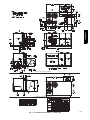
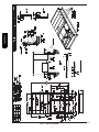
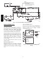
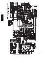
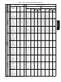
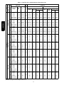
50HCQD12
C10846
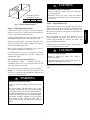
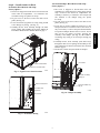
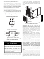
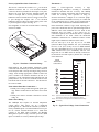
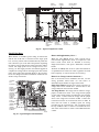
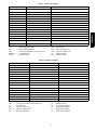
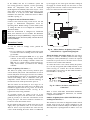
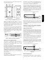
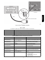
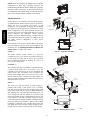
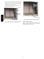
Fig. 1 - Unit Dimensional Drawing – 12 Size Unit (cont.)
INSTALLATION
Jobsite Survey
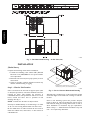
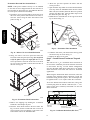
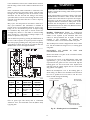
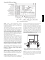
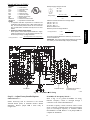
18”
(457) *
Complete the following checks before installation.
1. Consult local building codes and the NEC (National
Electrical Code) ANSI/NFPA 70 for special installation requirements.
2. Determine unit location (from project plans) or select
unit location.
3. Check for possible overhead obstructions which may
interfere with unit lifting or rigging.
42"
(1067)
42"
(1067)
42"
(1067)
* Required bottom condensate drain connection.
Otherwise, 36” (914mm) for condensate connection.
Step 1 — Plan for Unit Location
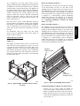
Select a location for the unit and its support system (curb
or other) that provides for at least the minimum clearances
required for safety. This includes the clearance to
combustible surfaces, unit performance and service access
below, around and above unit as specified in unit
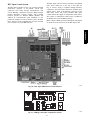
drawings. See Fig. 2.
NOTE: Consider also the effect of adjacent units.
Unit may be installed directly on wood flooring or on Class
A, B, or C roof--covering material when roof curb is used
Do not install unit in an indoor location. Do not locate air
inlets near exhaust vents, relief valves, or other sources of
contaminated air.
C10849
Fig. 2 - Service Clearance Dimensional Drawing
Although unit is weatherproof, avoid locations that permit
water from higher level runoff and overhangs to fall onto
the unit.
Select a unit mounting system that provides adequate
height to allow for removal and disposal of frost and ice
that will form during the heating-- defrost mode as well as
allow installation of condensate trap per requirements.
Refer to Step 9 — Install External Condensate Trap and
Line – for required trap dimensions.
4