1
1 Specification
EUROCOM-17-5xx
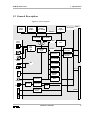
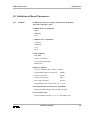
The integrated real-time clock allows the operating system to provide date
and time for revision control. The clock is powered by an internal lithium
battery. 2 (8, 32) KB of battery-backed RAM are used for storage of
system dependent parameters.
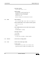
An AT-compatible keyboard input (using a 6-pin PS/2 compatible
connector) along with the graphics output provides a PC-type user
interface.
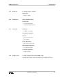
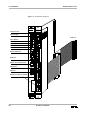
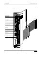
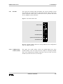
Status display, reset switch, and two hex-code switches are located on the
front panel. The status display indicates the condition of the processor and
watchdog status. The hexadecimal display is an error status display. The
hex-code switches (software readable) are used by the firmware to set up
the operating mode and the VMEbus base address of the board.
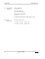
The VMEbus interface of the EUROCOM-17-5xx uses the VIC068
VMEbus Interface Controller gate array. Optionally, a VIC064 may be
used which supports D64 multiplexed block transfer according to IEEE
1014 Rev. D.
A 256 (512) K x 8 Flash EPROM holds the firmware. It is on-board
reprogrammable to allow reconfiguration.
Up to 1M x 8 EPROM can be added to the board to hold user firmware.
The on-board Ethernet interface provides connection to most popular local
area networks (LAN).
A sophisticated SCSI-2 (wide) interface is also located on the
EUROCOM-17-5xx. The controller chip is very fast and intelligent so that
it forms a very efficient SCSI interface with max. transfer rates of
20 MB/s.
The on-board local extension bus (LEB) allows easy hardware extension
of the EUROCOM-17-5xx using ELTEC IPINs. The LEB of the
EUROCOM-17-5xx supports dynamic bus sizing.
6
Hardware Manual