1
.
United States Patent [191
[l 11
4,265,371
Desai et a].
[45]
May 5, 1981
[54]
FOODSTUFF VENDING APPARATUS
EMPLOYING IMPROVED SOLIDSTATE
3,777,937
4,011,967
TYPE CONTROL APPARATUS
[75] Inventors: Mahendrakumar 1). Desai, Colonia,
N.J.; Drew Henderson, Georgetown,
Com
[73] Assigneei Trafalgar Industries Inc" New York’
N-Y~
l2/l973
3/1977
Buck .................................... .. 222/70
Halsey et a]. ........................ .. 222/70
Primary Examiner—Joseph J. Rolla
Alwmey. Agem- or Firm-Lerner. David, Lirrenberg &
Samuel
[57]
ABSTRACT
Foodstuff vending apparatus employing improved so
lid-state control is provided in accordance with the
[21] AppL No’: 949,052
teachings of the present invention. In accordance with
_
the teachings of the present invention, a processor and
[22]
plied:
[51]
[52]
Int. Cl.3 ............................................. .. B67D 5/06
us. Cl. ................................. .. 222/70; 222/1294;
3(,4/9()()
Field of Search .................. .. 222/70, 1294-1294,
ing to Occur in a Programmed sequenc? in accord with
selected vending conditions The processor and mm
ory are programmed in a manner to ascertain when a
vending Operation is about to be initiated and thereafter
222/52, 59, 75; 364/900
to invite an operator to specify a product to be vended
[58]
08' 6’ 1978
accompanying memory are relied upon to cause vend
,
and conditions under which such product is to be
[56]
References C'ted
US. PATENT DOCUMENTS
3,409,176 ll/l968 Krause ........................ .. 222/1294 x
Coja __________ u
3,638,832
3,688,947
2/l972
9/1972
REAL TIME
SERVICE
x
selectable rates
Sauber et a].
222/76 X
Reichenberger ........... .. 222/ 129.1 X
TIMER
lOMlLLSEwNDS I060
(RT SERV)
vended. Elements of the product to be vended are then
dispensed, under program control, in accordance with
the Product designated and the. conditions speci?ed at
HARDWARE
TIMER
TIME
TIMER STACK
Ho
42 Claims, 3 Drawing Figures
START TIMER
"3b
ACTIVE
DECREMENT
COUNT
START
RETURN TO
EXECUTIVE
||
CUE STACK
(TASKS) l2
PUT TASK
IN CUE
STACK
"30
are readily Vii-"able.
U.S. Patent
P
Plcl 2
PI 1/
May 5, 1981
Sheet 1 013
4,265,371
P10
1111111111
PMEmDF mOwFzdEh
FIG. lo
US. Patent
May 5, 1981
Sheet 3 of 3
4,265,371
7923m
zww2962 uF25 6
5EQ58
._zwsmo P230
NQE
4,265,371
1
2
of the apparatus, and, at the same time, increasing the
FOODSTUFF VENDING APPARATUS
EMPLOYING IMPROVED SOLID-STATE TYPE
CONTROL APPARATUS
BACKGROUND OF THE INVENTION
Automatic vending machines are quite well known
and are employed in just about every conceivable physi
cal location such as, for example, factories, office build
ings, institutional and education facilities, retail estab
lishments, public gathering places, airport terminals,
train stations, and the like. Automatic vending machines
are utilized to vend a wide variety of items, including
solid, as well as liquid based foodstuffs. Vending ma
chines for vending liquid based foodstuffs such as hot
and cold drinks, soup, and the like, typically offer a
selection of foodstuff ingredients which may be com
bined with a liquid or selections wherein the liquid may
be combined with one or more foodstuffs added in vary
ing degrees of strength or concentration in accordance
with the particular selection. For example, a coffee
vending machine may offer black coffee, coffee with
capability and versatility of the vending apparatus.
The microcomputer includes memory means for stor
ing a program adapted to initiate all of the vending
machine functions typically performed either mechani
cally or electromechanically in conventional vending
apparatus, as well as incorporating new and unique
functions and capabilities to provide equipment which
is less complicated from a maintenance and servicing
viewpoint and which is more reliable due to the signi?
cant reduction in the number of mechanical and electro
mechanical components utilized in the system, as well
as providing flexibility not capable of being attained
with conventional apparatus.
As is the case with conventional equipment, opera
tion is begun by the insertion of a coin. Recognition and
acceptance of a valid coin invites the apparatus operator
to select the desired drink and its ingredients and/or
strength of ingredients. The program provides for the
20 multiplexed use of a common bank of switches such
that, in one preferred embodiment, a bank of eight
switches are operated to provide up to 24 different
selections, if desired.
cream, coffee with sugar and cream, etc. As regards
Based upon the particular selection, the program
concentration, the machine may offer coffee with 25 follows the appropriate program routines associated
cream, coffee with extra or double cream, coffee with
with the selections made. For example, upon selection
sugar, coffee with double sugar, and so forth.
of a particular hot drink, the appropriate amount of
The amount of each ingredient dispensed is conven
liquid and other ingredients making up the drink are
tionally controlled by cam operated switches which
dispensed into a common mixing bowl which, in turn,
control the duration of energization of a dispensing 30 dispenses the admixed ingredients into a common recep
device. For example, in locations in which it is required
tacle. Each of the ingredients is dispensed substantially
that an eight ounce drink is to be dispensed, the liquid is
simultaneously or in overlapping intervals, although in
passed therethrough at a predetermined flow rate. By
certain instances, some ingredients may be dispensed in
adjustment of the cam operated switch means, the valve
sequential fashion. The dispensing interval for each
may be energized, i.e., maintained in the open position, 35 ingredient is basically a function of the amount of the
for an interval which is related to the ?ow rate so as to
ingredient to be dispensed. For hot drinks, the hot water
be sufficient to dispense the desired quantity of liquid.
is typically dispensed over the longest time interval in
Similar cam operated switches are utilized to control
the interval of energization during which powdered
order to serve as the admixing medium, as well as the
liquid based ingredient of the drink.
ingredient dispensing means are maintained operative to 40
Determination of the quantity of liquid and of the
dispense the proper quantity of the powdered ingredi
ingredients to be dispensed, as well as the simplified and
ent.
yet precision adjustment of the amount of ingredient to
Typically, it becomes necessary to make adjustments
be dispensed, is accomplished through the cooperative
in the cam operated switches in order to control the
relationship of the microcomputer in cooperation with
amount of the ingredient being dispensed to compensate 45 settable switch means. For example, in order to dispense
for differences in dispensing devices, etc., and, although
a desired amount of liquid, the program, at a predeter
the cam assemblies are designed to be adjusted, such
adjustments are quite difficult and require “cut and try”
techniques before the proper adjustment is obtained,
thus making maintenance and/or machine installation a
tedious and complicated procedure.
The overall number of mechanical switches neces
sary to provide the desired number of selections further
complicates the vending machine. In addition, mechani
mined point in the routine, develops a dispensing con
trol signal to initiate operation of a solenoid or a motor,
for example, depending on the particular ingredient.
50 The processor also causes a scan signal to be applied to
the input of each switch means associated with those
ingredients to be dispensed. The scan signal appears at
one of the plurality of outputs of the switch, dependent
upon the setting of the adjustable switch arm. This
cal switches of both the selection and cam operated 55 output is converted into a time value and is stored in a
type are subject to wearing, requiring added mainte
nance activity.
BRIEF DESCRIPTION OF THE INVENTION
The present invention is characterized by providing a
solid-state
microcomputer
based
control
system
adapted to convert most, if not all, of the conventional
register in the computer. During a vending cycle, the
aforesaid register cooperates with the microprocessor
in such a manner as to function as a timer which has its
contents altered, such as being decremented by a timing
pulse developed by the processor. When a predeter
mined count is reached in the register, i.e., when the
register “rolls over”, the task associated with that timer
value is performed. In this case, the aforesaid solenoid is
turned off, terminating the dispensing time interval for
functions of a vending machine typically performed by
mechanical apparatus into electronic signals and/or
electronic control operations, thereby remarkably re 65 the ingredient being dispensed.
ducing the number of mechanical and electromechani
A cycle timer, preferably in the form ofa register and
cal components otherwise required in conventional
decrementing means, initiates the energization of each
apparatus, as well as reducing the size and complexity
dispensing device dependent upon the operator‘s selec
3
4,265,37l
tion and in a predetermined sequence. The time value
for each activity to be performed is set into an associ
ated time register for each ingredient at this time, is
decremented and is tested for “roll over", at which time
the task for that time interval is performed. The task
may be one which starts a dispensing interval, as well as
one which terminates a dispensing interval.
The powdered ingredients are preferably dispensed
during the time that the liquid ingredient is being dis
pensed in order to take advantage of the ?ow of water 0
to admix the foodstuff ingredients within the appropri
ate mixing bowl. Each timer count is then preferably
independently decremented and then examined to de
4
switch to simply and yet accurately control the amount
of each ingredient to be vended.
Another object of the invention is to provide an over
all apparatus timer which automatically resets the mi
croprocessor in the event that dispensing operations are
not performed within an outside limit.
The above, as well as other objects of the present
invention, will become apparent from reading the ac
companying description and drawings in which:
FIGS. 1a and 1b are block diagrams which, taken
together, show a vending apparatus embodying the
principles of the present invention.
FIG. 2 shows a detailed flow diagram of a program
utilized for controlling the apparatus of FIGS. 10 and
the dispensing operations at a time in accordance with 5 1b.
the count originally set into each timer register. Adjust
DETAILED DESCRIPTION OF THE
ment of the settable switch means permits a plurality of
INVENTION
precise, programmable settings. Also, an interval
FIGS. 10 and 1b show a control system 10 for operat
counter in the computer is programmable to alter unit
timing, and the scale factor for each ingredient may be 20 ing a vending machine and embodying the principles of
the present invention. The system 10 is comprised of a
altered if desired. In one preferred embodiment, the
processor 11 which may, for example, be an Intel mi
basic time interval value is programmable to obtain time
crocomputer of the MCS-48 system described in the
intervals ranging from as small as 10 milliseconds to as
text “Intel MCS-48 Microcomputer User's Manual“,
large as 2.55 seconds. Even higher values can be ob—
termine if it has rolled over to start or terminate each of
tained if desired to accomplish simpli?ed changes in the
copyright 1976 by Intel Corporation. The processor
vending cycle time, powder drop times and soda/ syrup
dispensing time.
typically includes a central processor (CPU), program
memory (ROM), data memory (RAM), input output
The pumps and/or drive motors used to dispense the
aforementioned ingredients are energized through the
selective operation of reed switches which isolate the
low dc. power utilized to power the control circuitry
from the high ac. power utilized to drive the pumps and
drive motors. The reed switches operate triacs such that
the reed relays drive the triacs in both directions, pro
viding full cycle a.c. on/off control especially advanta
(I/O) lines, and an event counter. The CPU typically
geous for use with ac. shaded pole motors.
Means are provided to monitor the ac. power source
may be derived from a conventional wall outlet. Main
switch 56 selectively couples ac. power from plug 12 to
and to energize motors, solenoids and the like only
transformer TR] whose primary TRlp is coupled to
input terminals 12 and whose secondary windings
during a substantially zero crossover of the a.c. source.
comprises control circuits, registers and an Arith
metic/Logic Unit (ALU). For example, the block dia
gram appearing on page 2-—2 of the aforesaid manual
shows the conventional processor hardware con?gura~
tion and is incorporated herein by reference thereto.
Sixty (60) Hz ac. power is coupled to the input termi
nals of plug 12 from a power supply (not shown) which
In the event of power brownout, the program is auto 40 TRlsa and TRlsb are respectively coupled across the
matically reset to prevent the vending apparatus from
performing incorrectly.
Any spurious signals or power disturbances which
might cause a jump in the program beyond the ?nal
input terminals of full wave diode bridges DB1 and
DB2. The output terminals of the diode bridge DB1 are
coupled between ground reference and the smoothing
and ?ltering circuit 15 to develop a dc. level+VDC
program step to an invalid memory location also cause 45 which is utilized to power the microprocessor 11 and
other components of the control circuitry.
an automatic resest of the program.
OBJECTS OF THE INVENTION AND BRIEF
DESCRIPTION OF THE FIGURES
It is, therefore, one object of the present invention to
provide a novel solid-state control for vending ma
chines.
Another object of the present invention is to provide
novel solid-state control means for vending machines,
said control means being microcomputer based control
apparatus having an operating program which provides
for a large plurality of vending selections.
The (+) output terminal of diode bridge DB1 is also
coupled through diode CR1 to a do reference level
circuit including capacitor C2, resistor R17 and zener
diode CR2, which elements form part of the undervolt
age detection circuit 14. The reference level is applied
to the non-inverting input 16a of operational ampli?er
16, whose inverting input 16b is coupled to the opposite
terminal of resistor R30 through series resistor R18 to
couple the signal being monitored to operational ampli
?er 16. The output of operational ampli?er 16 is cou
pled through resistor R23 to the reset input 110 of mi
Still another object of the invention is to provide a
croprocessor ll. Diode CR1 rapidly charges capacitor
microprocessor control for vending machines and the
C2. Diode CR2 and high ohmic resistor R17 cause the
like which monitors a number of conditions to assure 60 capacitor C2 to discharge at a very slow rate.
that switching and control operations are performed
only during acceptable states of the conditions being
monitored.
Still another object of the present invention is to
Output terminal 11b of the microprocessor develops a
signal whenever a program counter, provided in the
processor, steps to a count which exceeds the preestab
lished capacity of the internal memory storing the pro
provide novel solid-state control means for vending 65 gram, thereby indicating an invalid condition. In such
event, such output at 11b is coupled to the input of
machines and employing switches which are manually
inverter 17 and the parallel connected RC combination
settable for simply and readily adjusting the vending
of resistor R24 and capacitor C13, to the inverting input
duration of the ingredient associated with the selectable
5
4,265,371
16b of operational ampli?er 16 for the purpose of devel
oping a reset signal for initializing the processor and
resetting the program to the starting point in readiness
for accepting the next coin drop in the event that the
maximum number of program steps is exceeded, for any
reason, such as spurious signals in the system, ambient
noise, and the like.
6
to terminate the dispensing of powders if water flow is
interrupted. The condition is applied to input 11d of
microprocessor 11. This input is typically referred to as
the T0 input of the microprocessor in the above-men
tioned manual.
A credit impulse interface circuit 22 is comprised ofa
The undervoltage detection circuit 14 independently
pair oflight emitting diodes, LED] and LEDZ, respec
tively, coupled in parallel and with opposing polarity
performs a similar reset function upon detection of a
across a.c. return lead 23 and one terminal of resistor
drop in operating voltage at the inverting input 16b
R32. The opposite terminal of resistor R32 is coupled to
the coin receiving mechanism (not shown) which cou
ples ac. power through coin switch 63 to LEDl and
LEDZ when a coin has been deposited. The light emit
ted by LED! and LEDZ during alternate half-cycles of
the ac input activates phototransistor Ptl to provide a
relative to the slow-to-change reference level applied to
its non-inverting input 16a to develop a reset triggering
signal at the input 11a ofthe processor. A similar result
is obtained when the input to the inverter 17 derived
from the microprocessor output terminal 11b goes high
to develop a low level signal at the inverting input 16b
of operational ampli?er 16 to thereby develop a reset
output signal which automatically resets the program to
its starting point in the presence of either an undervolt
low level to one input of NAND gate 25 whose other
input is normally maintained at a high level by the sup
ply source +VDC through resistor R4. The aforesaid
remaining input of NAND gate 25 is also coupled to the
age condition or an invalid program step count, thereby 20 output of NAND gate 24 having one of its inputs nor
mally maintained at the +VDC source level through
respectively preventing low impulse noise on the power
resistor R3. The remaining terminal is coupled to one
line from being erroneously interpreted as a valid signal
output lle of microprocessor 11.
so as to avoid the possibility of the program entering
The output of NAND gate 25 is coupled to one data
into a random loop and preventing invalid program
input, DBO, of microprocessor 11. The optical isolation
steps from being erroneously interpreted as part of the
permits the use of any coin accepting device without
normal operation.
the need for any special electrical interface. Credit sta
A zero crossing detector circuit 18 is provided and is
tus is examined during the program to initiate the pro
comprised of transistor Q1 having its base electrode
gram cycle as will be more fully described hereinbelow.
coupled to the positive output terminal of diode bridge
DB2 through resistor R28, while its collector is coupled 30 Once credit is established, the program selectively
enables manually operable push buttons Pl-Pl4 pro
to the +VDC power supply level. The emitter of Q1 is
vided for the selection of the drink and the strength of
grounded. Each time the recti?ed, un?ltered 60 Hz
the ingredients. The push buttons are energized in a
signal goes substantially to zero (twice per cycle), the
multiplexed fashion to provide a signi?cant increase in
Q1 collector goes high to develop the zero crossing
signal which is inverted by inverter 19 and is applied to 35 the number of selections which can be made for the
same given number of operating push buttons and also
the interrupt input llc of microprocessor 11 which
reduces the number of input lines required to transfer
serves to interrupt or delay the performance of a
data from the push buttons to processor 11.
switching operation except during the time at which a
The push buttons P7-P14 are coupled through invert
zero crossing occurs, which operation is accomplished
in a manner to be more fully described hereinbelow. 40 ers 30-1 through 30-8 to the data input lines DB1
Zero crossings occur at twice line frequency or 120 Hz.
The system further includes a water flow sensing
circuit comprised of a silicon-controlled switch Q3 and
through DB7, which data is utilized during the program
cycle to dispense the selected drink having ingredients
of the selected strength. The push buttons Pl-P3 are
coupled to data lines DB'7-DB5, as are the push buttons
through collector coupled resistor R29. The anode of 45 P4-P6.
The enable lines of the push buttons are coupled to
switch Q3 is coupled to the positive (+) output of the
outputs 32a-32c of decoder 32, which decoder is
full wave diode bridge DB2 through resistor R25. The
adapted to enable only one of its eight output lines
Q3 cathode is coupled to ground through resistor R22
under control of a four bit binary control word applied
and is coupled to the base of Q2 through resistor R20.
The Q3 control electrode is coupled to the common 50 in the form of signal levels to its input lines 32j. 32k, 321,
and 32m, which are respectively coupled to output
terminal between resistors R26 and R19. A conven
control lines llj, 11k, 11m, and lln of processor 11. The
tional ?ow sensor (not shown) is coupled by terminals
states of the group of push buttons whose enable line
54 between the opposite terminal of R19 and ground.
has been activated are stored in predetermined locations
The sensor switch is normally open in the presence of
water How. The level ofthe voltage at the Q3 gate turns 55 in the processor‘s memory (RAM). This data is utilized
during the execution of a subsequent program routine to
Q3 on. The voltage drop across R22 turns Q2 on. The
develop time values as will be more fully described.
sensor switch closes in the absence of water flow to turn
Upon completion of that part of the program cycle
off silicon-controlled-switch Q3 and transistor Q2,
which determines the drink which has been selected
thereby placing a high level at the collector of Q2 and
and the strength of the ingredients for the selected
at the input of inverter 20 and a low level at input 11d
drink, selected ones of the battery of switches Sl-S13
of the microprocessor 11. When one ofthe water valves
are scanned to determine the time intervals during
is opened and water flow from the water tank is normal,
transistor Q2. Q2 is powered by the +VDC supply
the sensor contacts across terminals 54 are normally
which each dispensing device for the appropriate ingre
open, causing the Q2 collector to stay low and to go
dients is to be energized. The switches are scanned by a
high only at the time of zero crossings, thereby placing 65 program routine which applies control signals to de
coder 32, decoder 33, and gate 34 through outputs
a high level upon input terminal 11d ofthe microproces
llj-lln and lle for selecting each switch to be scanned
sor, except at the instant at which a zero crossing oc
on a one-at-a-time basis and placing the signal states of
curs. This condition is used to monitor water flow and
7
4,265,371
8
dispensing freeze-dried coffee, for example. The re
maining power terminal is also coupled to the gate
electrode of the triac T2 through resistor R34 and
all output lines of the selected switch upon the data
input lines DB1~DB7 (for Slb-l through Slb-8), and
lines 1111, 11v and 11w (for Slb-9 through Slb-ll). It
should be understood that all output lines of like num
switch 37a which is now closed. As a result, the triac
gate triggers triac T2 on, and ac. power is coupled to
ber are connected in common to the same microproces
sor data input line. For example, output lines S1b-1
the ingredient dispensing apparatus comprising a dis
through SI3B-1 are all connected in common to data
line DB7, Slb-2 through S13b-2 are connected to data
line DB6, and so forth. Gate 34 serves to disable de
coder 33 when decoder 32 is selected and vice versa. In
pensing motor which drives the ingredient from a con
accordance with the position of switch arm Sla, only
ac. signal passes through zero to prevent arcing and
phase mismatch between power source and load,
tainer into a conventional mixing bowl (now shown) for
receiving the ingredients of the selected drink. As was
described hereinabove, switching is delayed until the
one output line ofswitch 51 carries the scan signal, This
thereby increasing the operating life of all circuit com
ponents. In addition, the triacs are capable of being
ing devices. The switch arms S1a-Sl3a of each of the 5 driven in both directions to provide full cycle a.c. on/
off control which is especially advantageous for operat
switches 51-513 are preset by maintenance personnel to
ing a.c. shaded pole motors. The reed relays provide
control the time duration of each dispensing device in
total isolation between the high power a.c. for operating
accordance with the needs of each location. Adjustment
condition is examined during that portion of the pro
gram cycle which controls the activation of the dispens»
the vending motors and the low power d.c. utilized in
is very simple. since it necessitates movement of the
switch arm into any one of the 11 discrete switch posi 20 the computer control circuitry. Also, the reed relays
provide an inexpensive switching device having long
tions and yet allows for accurate adjustment of the
amount of ingredient to be dispensed.
A subsequent routine of the program examines the
life and quick response characteristics. Other isolation
means such as opto-isolators may be employed if de
sired.
data representative of the switch settings of selected
switches to calculate the time interval for each of the 25
The computer control operation ofa typical program
cycle can best be understood from a consideration of
ingredients to be dispensed. The processor then devel
the ?ow diagram shown in FIG. 2 which will now be
ops signals which are coupled to output lines 11p—11t
considered in conjunction with the block diagram of
to respective inputs 350-1 through 351-5 of I/O expan
der 35 having three four-bit bidirectional static I/O
FIG. 1.
Assuming that the plug 12 has been inserted within an
ports 35b~35d which serve to couple control signals to
the selected dispensing motor and one four-bit port
energized wall socket, the system is powered by closing
350-2 to 3525 which serves as an interface to the micro
switch 56. (See FIG. 1). The power-on condition is
processor. Binary control signals appearing at outputs
sensed by the processor reset input to cause a reset of
llp~11t are applied to terminals 35a-l through 35:1-5 of
the program cycle as represented at 101 of FIG. 2.
Reset causes initialization of the system at 102, which,
upon deposit of a coin, begins a test credit routine under
control of a test signal periodically created at output
terminal 110 of processor 11 and applied to gate 24. The
port 350, and a clock input is applied at 35(1-1 to cause .
at least one terminal of each of the three four-bit ports
35b--35d to be shifted to the enable state in order to
enable at least one of the reed relays in four associated
groups of reed relays 36a, 36b, 36c, and 36d, respec
tively, each group incorporating four such reed relays
such as group 360 which incorporates reed relays 360-1
through 3604. The reed relays are identical in design
and function, and only one will be described herein for
purposes of simplicity.
gate 24 has its output normally maintained low, but is
caused to go high under control of the test signal peri
odically created at output terminal lie of processor 11.
In the event that no coin is present during a credit
check. or in the event that the coin switch contacts are
experiencing contact “bounce”, the output level of the
Considering reed relay 3601. the relay comprises reed
45 collector of Ptl will be high, developing a low level at
elements shown schematically as a switch arm 37a and
which elements are mechanically biased so as to pro
the output of gate 25, indicating the absence of credit as
represented by the NO condition at line 1015b in FIG. 2.
When a coin is deposited. coin switch 63 is closed to
vide a normally-open condition. Although not shown
for purposes of simplicity, the reed relay has its reed
elements encapsulated within a hermetically sealed
evacuated glass envelope. A solenoid winding 37b sur
rounds the hermetically sealed envelope and has one of
its terminals coupled to source +VDC through bus 65
and has its other terminal coupled to output line 3512-1
of I/O expander 35. The reed switch is designed to be
normally open when winding 37b is deenergized. A
diode 376 is coupled in parallel across winding 37b to
prevent damage to the I/O expander 35 due to induc»
tive “kick back" voltage. When it is desired that the
reed relay he maintained in the normally open state, the
establish an ac. path from bus 48 through the closed
coin switch to the light-emitting diodes LED] and
LEDZ to the opposite terminal being coupled to the a.c.
return. LED] and LEDZ are alternately energized,
causing light to be emitted from the LEDs during alter
nate half cycles of the ac. wave. The light is sensed by
phototransistor P11 to cause the output at the collector
PM to go low, causing the output of gate 25 to go high
to establish a credit condition.
This condition is represented by the YES signal path
10311 of the test credit operation 103 which causes a
pulse to be applied to a credit counter 184 (not shown),
ievel at tine 35b~1 is maintained at substantially the
power source level 'l- VDC. When it is desired to per~
provided within microprocessor 11, preferably in the
form the switching operation, the level at line 35b-]
of the working registers provided in the processor 11.
form of a dedicated location in memory (RAM) or one
drops to reference potential (typically zero volts or
As long as the count in counter 104 is less than a preset
ground) causing a current to pass through winding 37!) 65 number, output 1040 of the credit counter applies a
37a. A triac T2 has its power terminals respectively
level to the input of the test credit control to continue
the test for credit. Thus, the condition at gate 24 and,
coupled to the ac. return line and to a motor 66 for
hence, gate 25 is read into the microprocessor (at the 80
to establish a magnetic ?eld sufficient to close contact
4,265,371
microsecond rate) a plurality of times before credit is
established. Each valid condition read into the proces~
10
drop. The Timer Stack 110 comprises a group of mem
After a predetermined number of counts has been accu
ory locations, each capable of storing a time interval
and the task associated therewith. Timer stack pointer
110-a of the timer stack 110 is adapted to scan each of
mulated, output 1040 of the credit counter is disabled,
said memory locations and extract the contents thereof
and output 1114b is enabled to cause the program to
enter into the start operating system routine of the pro
gram cycle as represented at 103. This routine enhances
described. Selected ones of the memory locations in
the system‘s security.
locations are manipulated in a manner to be further
sor causes counter 104 to be incremented by one count.
for performing a particular function, to be more fully
timer stack 110 constitute the Cycle Timer 110-5, which
The above description presupposes that each test - 0 described. In addition, the completion of routine 109
credit pulse yields a “yes“ condition. In the event that
activates the program routine 111 which indicates that a
any of the tests for credit pulses result in a "no" condi
task has been placed within the cue stack 112. This
tion (i.e., switch is not closed), as represented by output
causes line 111a to initiate the executive routine 117
line 103b, the system is again initialized, and the credit
explained as follows.
test begins anew. Thus, the number of credit pulses 5
In the present example, as was noted previously, the
developed must occur in an unbroken series.
?rst task to be performed is the dropping of the cup.
Upon reaching the full count, the start operating
The word representing this task had been previously
system routine establishes at 105 an enable signal 105a
for hardware timer 106, as well as signal 10511, which
initiates the scan keyboard routine 107 of the program.
The hardware timer 106 is comprised of a multistage
loaded in the ?rst location 112-2 in the cue stack 112.
The cue stacker pointer 1100 looks for task words
stored in the stack and read out the ?rst task word
encountered in the cue stack, in this case, location
counter advanced by pulses occurring at 80 micro
112-2, requesting a cup drop. This stored task causes the
second intervals, said counter having stages suf?cient in
microprocessor 11 to control I/O expander 35 to ener
number to generate pulses at the timer interrupt output
gize the reed switch relay 36c-4 to cause its associated
1060 at l0 millisecond intervals.
25 triac to energize the cup drop motor 70 during the next
When the full credit condition is established, the full
zero crossing of the power source signal as will be more
count signal 1114b also develops an output signal which
illuminates the credit lamp 68. Note FIG. 1 wherein
output 35d-1 of I/O expander 35 energizes relay 36c-1
to close its associated reed switch and thereby establish
a current path across the a.c. power line to light the
credit lamp 68.
During the keyboard scan portion of the program
cycle, the microprocessor develops signals for control
ling decoder 32 to sequentially develop signals at its
outputs 32a-32c, respectively. A signal level is devel
oped initially on line 32b, enabling the line 48 coupled to
fully described. Depending upon the particular selec
tion made, and as previously noted, the times at which
remaining operations are to begin have been stored
within the cycle timerportion 110-5 of the timer stack
110. Such operations might include opening of the
water valve; energization of those dispensing motors for
dispensing each of the ingredients required to be dis
pensed for the selected drink; and so forth.
As part of the data collection portion of the cycle,
decoders 32 and 33 are controlled by the microproces
sor 11 to selectively scan those switches 5-! through
S-13 whose settings are associated with the ingredients
tons P1, P2, and P3, respectively. The depressed push
to be incorporated within the selected foodstuff. This
button couples the signal level on line 48 through its 40 data is stored in memory and is utilized to control the
associated inverter from the group of inverters 30-4 to
dispensing interval for each desired ingredient. Since all
30-2 to apply a data input signal to the associated line of
switches S1 through S13 are substantially identical to
the data inputs DB4-DB6, respectively. These lines are
one another with regard to both design and basic func
monitored for the presence of at least one switch clo
tion, only one switch will be described herein in detail.
sure among the three lines at a rate determined by the 45
Considering switch S1 which establishes the time
system clock which generates pulses at a pulse rate of 80
interval during which water is dispensed, its switch arm
microseconds. It should be noted that the data lines
Sla is movable to electrically engage any of the switch
DEG-DB7 can accommodate up to 8 push buttons, if
stationary contacts S1 b-1 through S1 b-ll. The switch
desired, to allow a similar number of drink selections.
arm Sla in turn is coupled to output 32d of decoder 32.
So long as a valid switch closure is present (and this is 50 Each of the stationary output terminals S1 b-1 through
determined by a predetermined count of pulses being
S1 b-11 is connected to an associated output line. These
accumulated in a key scan counter 108 in the processor),
lines couple stationary contacts 51 b-l through S1 b-8 to
the data is loaded into memory. When all three lines
the data input terminals DB1-DB7, respectively, of
32a-32c have been scanned, output 108a from scan
processor 11, while lines S1 b-9 through S1 b-ll are
counter 108 triggers the next program routine 109.
connected to the input lines llu, 11v, and 11w of the
During program routine 109, the ?rst operation to be
microprocessor 11.
performed (cup drop) is loaded from memory into the
The interval of time, I, during which the water is
cue stack 112. Cue stack 112 comprises a plurality of
dispensed is given by the equation I=minimum va
memory locations, each capable of storing a task word
lue-i-(scale factorX SS); wherein the minimum value is
and having a cue stack pointer 1120 which electroni
the smallest interval during which the water is to be
cally and continuously scans each of the memory loca
dispensed; the scale factor is determined by the base
tions in the cue stack and stops when it ?nds a task word
timing value for each ingredient, and SS is the switch
one stationary terminal Pla. Ma, and P30 of push but
in a memory location to undertake that task. Also, as
Setting.
part of routine 109, the initiate signal time values for all
As shown in FIG. 1, capacitors C5 and C6 and crystal
the remaining tasks associated with the selected drink 65 X1 form a clock which provides a frequency of the
and strength ofthe ingredients are loaded into the cycle
order of 5.7 MHz. This frequency is divided by an inter
timer location 110-S ofthe timer stack 110 with the time
nal clock provided in microprocessor 11 to generate
values bearing a set relationship with respect to the cup
pulses at a repetition rate of 10 milliseconds. For exam
11
4,265,371
ple, the internal clock may comprise a 16 bit counter to
divide the clock output in order to generate pulses oc
curring at 10 millisecond intervals.
Typically, the minimum value may be stored in mem
ory (ROM) in the form of a multi-bit digital word repre
12
described primarily in conjunction with FIGS. 1av 1b.
and 2:
The timer stack 110 is comprised of storage groups
110-0 through 110-4. Each group is capable of storing a
time interval value and the task word associated there
with. For example, storage group 110-0 is utilized to
store the interval during which water is to be dispensed;
location 110-1 stores the interval during which the
ing the ?rst switch position to be chosen, i.e., presuming
sugar
is to be dispensed; location 110-2 stores the inter
switch arm Sla to be engaged with stationary contact
val during which the powdered cream is to be dis
SIB-1, this represents a switch setting of zero, causing
pensed; 110-3 stores the interval during which the pow
the interval during which hot water is dispensed to be
dered coffee is to be dispensed; and the cycle timer
equal to the minimum value, i.e., I=minimum value+(
location 110-5 stores time values representing the in
scale factorXSS) or I=2.55+(l.0><0)=2.55. The re
at which the initiation of dispensing of each of the
maining switch positions represent integral multiples of 5 stant
above ingredients is to occur after dropping of the cup.
unity, i.e., “l(l.0)", “2><(l.0)”, "3X (l.0)", and so forth,
The hardware timer 106 emits a timer interrupt signal
so that the scale factor of 1 may be multiplied by a value
every 10 milliseconds to trigger the real time service
in the range from zero through ten (l0) to provide a
routine 112. As a result, timer stack pointer 110a is
time interval during which hot water (for example) is
controlled to sequentially scan the group 110-0 through
dispensed extending over the range of 2.55 seconds 20 110-5 and to extract the information stored therein. Due
minimum up to a maximum of 12.55 seconds.
to the fact that processor calculations are performed at
The water interval routine of the program cycle func
microsecond speeds, it is only upon the initiation of the
tions in the following manner:
dispensing of an ingredient that an interval computation
When the water valve is opened in a manner to be
is made for that ingredient and then placed in its appro
more fully described, the above equation is solved si 25 priate group location 110-1 through 1104 in the timer
multaneously therewith. The base value and scale value
stack 110. Therefore, if, for example, the ingredient
factors are withdrawn from their memory locations
whose time interval is normally stored in group 110-1
within the read only memory (RCM). The data repre
has not yet been dispensed, the timer interval for which
senting the 2.55 second interval. The scale factor (I
second) is stored in ROM in a similar fashion. Presum
senting the switch position is then read in by the micro
that ingredient yet to be dispensed will not have been
processor and is converted into a binary code form
calculated nor stored in group location 110-1. There
suitable for manipulation by the microprocessor. The
interval equation mentioned above is then solved using
the base value, scale factor and switch setting values to
determine the time interval over which the water is to
be dispensed. This time interval is stored with a task
word wherein the task word identi?es the task to be
performed at the end of the time interval, in this case, a
deenergization of the water valve to terminate water
flow. The time interval and its associated task work are
stored in a predetermined group location 110-1 through
fore, the information extracted from each group must be
tested (113 on FIG. 2) to determine if a time value has
been stored therein. If the value tested is beyond a pre
determined valid value, then the contents of the group
being examined is designated as "inactive" (i.e., it con
tains no useful information). If "inactive", the timer
stack pointer 1100 is advanced to select the next
group—~see line 1131) which activates routine 115. If the
contents represents a value which is valid, the group
40 contains “active” information and the time value stored
1104 according to the ingredient.
Adjustment of the switches S1-S13 is quite simple and
yet provides an accurate adjustment of the dispensing
interval. For example, vending apparatus in one loca
therein is decremented by 1 count. See 1130 (FIG. 2)
switch setting of 3, which when multiplied by the scale
factor of 1 yields 3+2.55 or a total dispensing interval
of 5.55 seconds. In the event that the same vending
has not been reduced to a zero count, the remaining
count is returned to its memory location, and the timer
stack pointer 110a advances to the next group (see line
equipment is desired to dispense eight-ounce drinks, the
1160 activating routine 115).
settable switch S1 need only be adjusted to increase the
dispensing interval by two seconds. The increment of
each adjustment may be reduced by storing a smaller
scale factor, if desired. For example, 0.8 seconds or 0.5
“rolled over" (i.e., stepped to zero), the "yes” condition
116b simultaneously triggers two operations, the first of
which initiates the decrement routine 114.
For a time value which is active and has been decre
mented at 114, said value, after having been decre
tion may be designed to vend drinks in a six-ounce cup. 45 mented by a count of 1, is tested to determine whether
it has reduced to zero, i.e., to determine whether the
The time interval required to dispense six ounces may,
counter has “rolled over", i.e., has been stepped to a
for example, be 5.5 seconds. Thus, switch arm Sla need
zero count. In the event the test indicates that the count
only be set to engage stationary contact S1b-4 for a
seconds, or even smaller values may be provided. The
reduced range may be increased by adding more sta
In the event that the value being examined at 116 has
which is that the task word associated with the value
which has just stepped to zero is inserted into the cue
stack 112 (see routine 111 which controls the cue stack
The switches for the powdered ingredients function
pointer 112-1 to put the task applied thereto into the
next available task storage location).
The other step simultaneously performed therewith is
in much the same way as that described hereinabove for
the hot water interval switch S1. Likewise, their accu
to disable the timer value at a “time-out" location by
inserting a code in the ?rst location of the timer value to
rate settings may be made in a simple and straightfor
ward manner greatly simplifying field adjustments as
compared with conventional cam switches.
The manner in which the interval during which each
ingredient to be dispensed is controlled will now be
prevent the value in that location from being counted
any further during the present vend cycle. This is the
tionary contacts. The added switch positions may be
stored as two data words.
“inactive" code referred to herein.
Each time a task is loaded into the cue stack, the
program is caused to jump to the task execute routine
13
4,265,371
(line 1110). The execute routine 117 looks to see if any
tasks are stored in the cue stack. In the event that the
cue stack 112 is empty, an inactive condition deter
mined at 118 causes the watchdog timer (which may be
14
zation of the hot water valve 73, 74 or 75 to enable the
flow of water to the appropriate mixing bowl. The next
task to be performed is the dispensing of sugar (motor
78) and then creamer (77) and then coffee powder (66)
a dedicated memory location or a register in processor
to the mixing bowl. All of these tasks constitute turn-on
11) to be incremented by one count and the program
jumps back to the scan keyboard routine to look for the
presence of any “extra ingredient“ requests. 1n the
event that a task is stored in the cue stack (indicated as
active at 11%), the watchdog timer is reset to a zero O
or energization of their associated motors or solenoids
to initiate dispensing of a particular ingredient. These
tasks all occur at predetermined time intervals measured
from the cup drop task and established by the values
stored in the cycle timer 110-5.
The times in which each of these dispensing intervals
count (119) and, based upon the particular task, the
microprocessor examines the zero crossing condition
are terminated are established by the values stored in
appearing at the interrupt input 11 of the microproces
groups 110-0 through 1104 which are decremented by
sor. In the event that a zero crossing is not present,
a count of 1 at ten millisecond intervals until they “roll
operation of the device called for by the task word is
delayed and the examination is repeated. The test is
over", at which time the task associated with the
counter which has just rolled over is entered into the
continuously repeated in this manner until a zero cross
ing condition occurs as indicated at 12%. at which time
cue stack.
The tasks are taken in the order in which they are
the task called for at 121 is performed. For example,
stored in the cue stack 112 and, depending upon their
assuming the task to be performed is the ?rst task, 20 identity, are caused to deenergize a valve or solenoid
namely, the dispensing of a cup, upon the occurrence of
identi?ed by the task word to cause termination of that
a zero crossing for the ac. signal, the signal is devel
particular ingredient.
oped through the I/O expander 35 to energize the relay
The program has been designed to require a number
of switch 36c-4 to energize the cup drop motor 70.
of program steps which is preferably no greater than the
Further tasks stored in the cue stack will be sequentially
internal storage capacity of processor 11. If the preset
performed (only at a zero crossing) until all tasks stored
number of valid program steps is exceeded (indicating a
in the stack 112 have been completed. When the last
malfunction), based upon the count of the program
task has been performed, this condition appearing at
counter, output line 11b goes high, causing inverter 17
122b terminates the cycle and initializes the system. This
to apply a low level to the inverting input of operational
may be accomplished by advancing the program
counter to a value exceeding the capacity of internal
memory (ROM) to develop the signal PSEN at output
116 of the microprocessor 11 to cause the program to be
reset in readiness for the next vending cycle.
The watchdog timer is reset every time a task occurs
and is incremented when no task occurs during the
executive loop. The watchdog timer (a multibit
ampli?er 16. This level is compared against the refer
ence level established at the noninverting input of oper
ational ampli?er 16 causing the operational ampli?er
output to apply a reset signal at 110 which serves to
reset or initialize the processor. More speci?cally, the
program counter of the microprocessor 11 is incre
mented after completion of each program step. In the
present system, the internal memory addresses are suf?
counter) times out after a predetermined interval during
cient to store the number of program steps required for
which no task has been performed since performance of
the last completed task, indicating a system malfunc 40 the vend cycle, including all drink selections. As soon as
the program counter calls for an address in memory of
tion. During the executive loop routine, the inactive
1024 (in decimal) or greater, the program store enable
condition (107b) triggers routine 118 to examine the
signal
(PSEN) is generated at output 116, typically
watchdog timer. 105b returns to the keyboard routine
employed to enable an external memory device. In the
and reenters into the executive loop which again trig
gers a search for tasks in the cue stack. This time, the 45 present system, the signal PSEN is coupled to the input
16b of operational ampli?er 16 through inverter 17 to
watchdog timer is incremented and the key scan routine
cause a signal to be applied to reset input 110 by the
is again reentered. However, any task discovered in cue
output of operational ampli?er 16.
stack 112 resets the watchdog timer to zero. Since a full
It should be understood that while this invention has
vend cycle should be completed within a maximum of
been described with respect to a particular embodiment
l2-l3 seconds, and, more frequently, in lO-l2 seconds,
thereof, numerous others will become obvious to those
and since a number of tasks (at least ?ve) occur during
of ordinary skill in the art in light thereof. For example,
each vend cycle, by setting the watchdog timer to re
the time values may be incremented, and time-out may
start the machine operation if some outside time limit is
occur when the stored count reaches full capacity.
reached, the system is provided with a backup capabil
Also, the time value may be stored and the contents of
ity in the remote event that all other safety checks fail to
an associated register is ?rst cleared and thereafter in
terminate system operation.
cremented at 10 millisecond intervals. and then com
The initiation of each dispensing operation can be
pared against the stored value after it is incremented.
seen to be preset in accordance with the cycle timer
When the stored count and the register count compare,
1105, while the termination of each dispensing interval
is controlled by the length of the time interval associ
ated with each of the turn-off tasks established by their
associated switches S1-S13. It should be noted that all
tasks, whether they be turn-on or turn-off ofa dispens
ing device, are transferred to the cue stack and per
formed in the order in which they are loaded onto the 65
cue stack. For example, the ?rst task performed is that
ofdropping a cup into the cup well. The next task to be
performed is the initiation of water flow, i.e., the energi<
the task is performed. Obviously, other alternatives may
be employed.
What is claimed is:
1. Means for dispensing a predetermined quantity of
material comprising:
a source of said material;
normally disabled dispensing means for dispensing a
measured amount of said material from said source
when enabled;
15
4,265,371
means responsive to a dispensing request signal for
enabling said dispensing means;
means comprises a timing pulse generator; means re
sponsive to enablement of said dispensing means for
timing means responsive to the enabling of said dis
pensing means for disabling said dispensing means a
selectable time interval after enablement, said tim
ing means including switch means comprising an
input. a plurality of outputs and a settable switch
arm for selectively coupling said input to one of
said outputs in accordance with the selected time
altering the count in said counter means upon the occur
rence of each timing pulse.
10. The apparatus of claim 9, further comprising
means responsive to a second count in said counter
means different from the count initially set therein for
disabling said dispensing means.
11. Means for dispensing predetermined quantities of
interval, counter means and transfer means respon»
sive to the setting of the switch means for setting a
count in the counter means representing the length
of time said dispensing means is enabled, and means
for altering the count in said counter means.
2. The apparatus of claim 1, further comprising means
for applying a scan signal to said switch means input;
said transfer means including count value development
means responsive to the output line carrying said scan
signal for developing a count value associated with the
switch means output carrying the scan signal, each of
said outputs being adapted to cause said count value
developing means to develop a different count value for
each switch output in accordance with the position of
each of a plurality of different materials in a predeter
mined sequence, comprising:
a source for each material;
normally disabled dispensing means for each source
for dispensing material from its associated source
when enabled;
sequencing means responsive to a dispensing request
signal for enabling said dispensing means in a pre
determined sequence and at spaced intervals of
time;
timing means associated with each dispensing means
responsive to enablement of its associated dispens
ing means for disabling its associated dispensing
said settable switch arm.
3. The apparatus of claim I, wherein said altering 25
means comprises a timing pulse generator; means re
altering the count in said counter means upon the occur
plurality of outputs, and a switch arm settable to
4. The apparatus of claim 3, further comprising means
couple said input to any one of said outputs in
accordance with the desired time intervalv
12. The apparatus of claim 11, wherein said timer
responsive to a second count in said counter means
different horn the count initially set therein for dis
abling said dispensing means.
means each comprise counter means and pulse means
for decrementing all of said counter means at a prede
5. The apparatus of claim 1, wherein said counter
means comprises a binary counter, said transfer means
termined pulse rate;
comprising means for converting the output states at the
outputs of said switch means into a multi-bit binary
means responsive to the reduction of the count in
each counter means to zero for disabling the dis
word and loading said binary word into said binary
pensing means associated therewith.
13. The apparatus of claim 11, wherein each of said
counter.
6. The apparatus of claim 5, further comprising means
timing means comprises a counter; means responsive to
the setting of the switch means associated with said
for generating a dispensing disabling signal when the
count in the binary counter is reduced to zerov
a source of each material:
timing means each including settable switch means
switch means being comprised of an input and a
rence of each timing pulse.
7. Apparatus for dispensing predetermined quantities
means at a selected time after its enablement, said
having a plurality of discrete switch positions for
adjusting the length of said selected time, each
sponsive to enablement of said dispensing means for
of each of a plurality of different materials comprising:
16
9. The apparatus of claim 7, wherein said altering
counter for setting a count into its associated counter:
pulse means for reducing the counts in all of the count
45 ers at regular timing intervals; and means responsive to
normally disabled dispensing means for each source
for dispensing the material from its associated
source when enabled;
timing means for each dispensing means responsive to
a zero count in each counter for disabling the dispensing
means associated with the counter whose count has
been reduced to zero count.
14. Means for dispensing a predetermined quantity of
the enabling of its associated dispensing means for 50 material into a receptacle, comprising:
disabling its associated dispensing means a select
a source of said material;
able time interval after enablement;
normally disabled dispensing means for dispensing a
each of said timing means including switch means
comprising an input, a plurality of outputs, and a
measured amount of said material from said source
settable switch arm for selectively coupling said
means responsive to a dispensing request signal for
generating a dispensing enabling signal and a scan
input to one of said outputs in accordance with the
selected time interval, counter means and transfer
means responsive to the setting ofthe switch means
for setting a count in the counter means represent-
ing the length of time said dispensing means is 60
enabled and altering means for altering the count in
said counter means.
8. ‘the apparatus of claim 7, wherein said counter
into said receptacle when enabled;
signal;
switch means comprising an input for receiving said
scan signal, a plurality of outputs and a manually
settable switch arm for selectively coupling said
input to one of said outputs in accordance with the
desired quantity of said material to be dispensed;
means comprises a binary counter, said transfer means
timer means;
means coupled to said switch means outputs and
comprising means for converting the output states at the
outputs of said switch means into a multi‘bit binary
word and loading said binary word into said counter
of the switch means for setting a time value in said
timer means in accordance with the setting of said
l'llL’illlE-r.
switch arm;
responsive to said scan signal applied to the input
17
4,265,371
means for operating said timer means responsive to
the enabling of said dispensing means;
means responsive to time-out of the timer means in
accordance with the time value setting for dis
abling said dispensing means.
15. The dispensing means of claim 14, wherein said
terminating the vending operation when the dc. level
falls below said reference level.
22. Vending apparatus including a processor pow
ered by a low power d.c. source;
a plurality of dispensing devices each adapted to
timer means comprises a counter; and said timer operat
ing means comprises timing pulse generating means for
altering the count in said counter.
16. A method for controlling vending apparatus hav
ing a plurality of dispensing means, each adapted to
dispense a different ingredient, and settable switch
dispense a separate ingredient and being powered
by an a.c. source;
said processor including coupling means for selec
tively coupling said a.c. source to said dispensing
means, each associated with a dispensing means and
being settable in accordance with the desired quantity
of the associated ingredient to be dispensed, wherein the
method is comprised of the steps of:
examining the drink selection push buttons manipu
lated by the operator to establish which ingredients
means in accordance with a predetermined se
15
are to be dispensed;
?rst level when it is desired to energize its associ
ated dispensing means and a second level when it is
desired to terminate energization of its associated
sequence;
examined switch settings into values representative
of the quantity of the associated ingredients;
storing each of said values;
dispensing means;
low power d.c. operated control means having input
25
generating timing pulses;
altering the counts of each of the aforesaid stored
values upon the occurrence of each timing pulse;
triac means having ?rst and second electrodes cou
pled between said dispensing means and said a.c.
power source;
each of said triac means further comprising a control
electrode coupled to an associated one of said out
a second value.
17. The method of claim 16, further comprising the
steps of:
providing a.c. power for powering said dispensing
put means for rendering the triac conductive when
its associated output means is activated, whereby
the processor controls coupling of the dispensing
means;
examining the a.c. power signal to ascertain the oc
currence of zero crossings;
40
next zero crossing of the power source signal.
18. The method of claim 16, wherein one of the dis
pensing means includes means for dispensing a liquid 45
ingredient and further comprising the steps of:
continuously monitoring the flow of liquid; and
means to said a.c. source while completely isolating
said do. source from said a.c. source; and
means for monitoring the a.c. power level for delay
ing switching of any of said dispensing means ex
cept during a substantially zero crossing condition
of the signal emitted by the a.c. source.
23. The vending apparatus of claim 22, wherein each
control means comprises a reed switch assembly, said
promptly halting the dispensing operation in the
input means comprising a winding, and said output
comprising a reed switch operated by said winding.
24. A method for controlling vending apparatus hav
ing a plurality of dispensing means, each energizable by
event of the absence of liquid flow during the time
that the dispensing means for dispensing the liquid
is enabled.
19. The method of claim 16, further comprising the
steps of counting the number of program steps in the
program which operates the processor for controlling
the vending operation;
immediately terminating the vending operation when
means coupled to each of said outputs and being
enabled when the associated output of said cou
pling means is at said ?rst level;
said control means having output means electrically
isolated from its associated input means and being
activated when its associated input means is acti
vated;
disabling the associated dispensing means when the
predetermined count associated therewith reaches
delaying the enablement and disablement of each of
said dispensing means until the occurrence of the
quence;
said coupling means further including means having a
plurality of outputs, each associated with one of
said dispenser means for generating a signal of a
enabling those dispensing means associated with the
ingredients to be dispensed in a predetermined
scanning those settable switches associated with the
ingredients to be dispensed and converting the
18
rectifying and ?ltering the a.c. signal to establish a
dc. level; and
deriving a reference level from said do. level; com
paring said d.c. level with said reference level; and
an a.c. signal, each adapted to dispense a different ingre
55
the count exceeds a predetermined count to estab
lish that the program counter has advanced to a
count requesting an invalid program step.
20. The method of claim 16, wherein the processor is 60
powered by a conventional a.c. power source and fur
ther comprising the steps of monitoring the output of
the power source and immediately terminating the
vending operation when the output ofthe power source
falls below a predetermined level.
65
21. The method of claim 20, wherein the step of de
tecting the level of the power source further comprises
the steps of:
dient, and having a group of manually operable selec
tion buttons, wherein the method is comprised of the
steps of:
(a) examining the selection buttons manipulated by
the operator to establish which ingredients are to
be dispensed;
(b) enabling those dispensing means associated with
the ingredients to be dispensed in a predetermined
sequence;
(c) disabling each dispensing means when the desired
amount of ingredient has been dispensed;
(d) examining the a.c. signal to ascertain the occur~
rence of zero crossings;
(e) delaying the enablement and disablement of each
of said dispensing means until the occurrence ofthe
next zero crossing of the a.c. signal coincides with
19
4,265,371
20
switch means in a predetermined sequence.
whereby said dispensing means are enabled in a
the enabling operation and with the disabling con
trol condition.
predetermined sequence, while each timer means
25. The method of claim 24, wherein one of the dis
pensing means includes means for dispensing a liquid
controls the disabling of its associated dispensing
ingredient and further comprising the steps of continu- 5
ously monitoring the ?ow of liquid and promptly halt
ing the dispensing operation in the event of the absence
of liquid flow during the time that the dispensing means
means to dispense the desired amount of each mate
rial.
30. A method employing settable switch means for
operating a normally disabled dispensing means to dis
for dispensing the liquid is enabled.
pense a measured amount of material derived from a
26. The method of claim 24, further comprising the
steps of counting the number of program steps in the
program which operates the processor for controlling
source of said material into a receptable when enabled,
said method comprising the steps of:
generating timing signals at a predetermined uniform
rate;
the vending operation;
immediately terminating the vending operation when
the count exceeds a predetermined count to estab 5
lish that the program step count has advanced to a
value requesting an invalid program step.
27. The method of claim 24, wherein the power for
operating the processor is derived from a conventional
ac power source and further comprising the steps of:
converting the ac. signal from the ac. power source
enabling said dispensing means upon the occurrence
of a dispensing request;
scanning the switch means to determine a value in
accordance with the setting of the settable switch
means, which value represents a predetermined
time period;
counting said time signals;
disabling the dispensing means when the number of
timing signals counted compares with said value,
whereby the desired amount of said material is
to a d.(:. signal;
monitoring the dc. signal and immediately terminat
ing the vending operation when the dc. signal falls
dispensed into the said receptacle.
25
below a predetermined value.
3]. A method employing settable switch means hav
28. The method of claim 27, further comprising the
ing an input and a plurality of outputs for operating a
steps of:
normally disabled dispensing means to dispense a mea
deriving a reference level from said do. level; and
sured amount of material derived from a source and said
comparing said d.c. level on said reference level to
material into a receptacle when enabled, said method
terminate the vending operation when the dc. 30
comprising the steps of:
level falls below said reference level.
generating timing signals at a predetermined uniform
29. Means for sequentially dispensing predetermined
amounts of disparate materials, comprising:
rate;
a plurality of sources of said materials, each of said
plurality of sources being associated with one of 35
said disparate materials;
tative of the output of the switch means carrying
the scan signal in accordance with the setting of the
settable switch means;
reducing the count in the counter by one upon the
adapted for dispensing a measured amount of mate
rial from its associated source when enabled;
means responsive to a dispensing request signal for
generating a dispensing enabling signal and a scan
signal;
a plurality of switch means, each comprising an input
for receiving a scan signal, a plurality of outputs
and a manually settable switch arm for selectively 45
coupling said input to one of said outputs in accor
dance with the desired quantity of material to be
dispensed from its associated source;
means;
applying a scan signal to the input of the switch
means and setting a count into a counter represen
a plurality of normally disabled means, each being
timer means associated with each of said switch
enabling said dispensing means upon the occurrence
of a dispensing request;
occurrence of each timing signal generated after
the setting of said count;
disabling the dispensing means when the count in the
counter equals a second predetermined count less
than said set count, whereby the desired amount of
said material is dispensed into the said receptacle.
32. A method for sequentially dispensing predeter
mined measured amounts of a group of disparate materi
50 als wherein each material is derived from a source, and
means for coupling said dispensing enabling signal to
a first one of said dispensing means and for cou
pling said scan signal to the input of that switch
means associated with said ?rst one of said dispens
each source includes a normally disabled dispensing
means for dispensing its associated material when en
abled, and whereby each quantity dispensed is accu
rately determined by plural settable switch means, each
55 having an input and a plurality of outputs, each switch
ing means;
means being associated with one of said dispensing
means responsive to the output of said last mentioned
means, said method comprising the steps of:
switch means carrying the scan signal for setting a
enabling selective ones of said dispensing means upon
time value in the associated timer means represen
the occurrence of a dispensing request and count
tative of the setting of the switch arm of said last
ing the timing signals starting with said next occur
mentiond switch means;
ring timing signal for each dispensing means which
means responsive to the enabling of said dispenser
is enabled;
means for starting its associated timer means;
means responsive to time out of each timer means for
applying a scan signal to each switch means in se
disabling the dispensing means associated with the
65
timer means which has just timed out;
said coupling means comprising sequencing means
quential fashion and establishing a time value rep
coupling said dispensing enabling signal to said
ofa settable switch arm of the switch means being
dispensing means and said scan signal to said
scanned;
resentative of that output of the switch means car
rying the scan signal in accordance with the setting
21
4,265,371
measuring elapsed time for each dispensing means as
the dispensing means is enabled;
disabling each enabled dispensing means when the
elapsed time measured compared with its associ
ated time value.
22
set therein for disabling the dispensing means
whose associated counter means has reached said
second count.
35. A method which employs settable switches for
preparing a liquid based foodstuff in a receptacle by
33. A method for sequentially dispensing predeter
operating plural normally disabled dispensing means
mined measured amounts ofa group of disparate materi
adapted to dispense measured amounts of ingredients
als wherein each material is derived from a source, and
each source includes a normally disabled dispensing
means for dispensing its associated material when en
derived from sources of said ingredients, said ingredi
ents being dispensed into said common receptacle,
wherein the method comprises the steps of:
generating timing signals at a predetermined uniform
rate;
abled, and whereby each quantity dispensed is accu
rately determined by plural settable switch means, each
having an input and a plurality of outputs, each switch
means being associated with one of said dispensing
means, said method comprising the steps of:
enabling each of said dispensing means in accordance
with a predetermined sequence;
scanning the inputs with a scan signal to establish a
time value representative of that output of each
switch means carrying the scan signal in accor 20
dance with the setting of a settable switch arm of
each switch means;
for each dispensing means, measuring the elapsed
time since enablement of each dispensing means;
disabling each enabled dispensing means when the 25
elapsed time measured compares with the time
value established by the switch means associated
with that dispensing means.
34. Means for preparing a liquid based foodstuff in a
receptacle, said liquid-based ingredient being comprised
of a liquid admixed with at least one non-liquid ingredi
ent, preferably in powdered form, comprising:
a source of said liquid-based ingredient;
at least one source of a powdered ingredient;
a plurality of normally disabled dispensing means, 35
each associated with one of said sources for dis
pensing a measured amount of the ingredient asso
ciated therewith into said common receptacle
when enabled;
timing means for generating regularly spaced timing
pulses;
means responsive to a dispensing request signal for
generating a dispensing enabling signal and a scan
enabling a first one of said dispensing means upon the
occurrence of a dispensing request;
applying a scan signal to the input of the switching
means associated with the enabled dispensing
means and setting a count in a register associated
with each switching means dependent upon the
output of the switching means which carries said
scan signal in accordance with the setting of the
settable switch means associated with the ingredi
ent being dispensed;
counting the number of timing signals generated after
the setting of said count;
disabling said ?rst one of said dispensing means dis
pensing the first mentioned ingredient into said
common receptacle when the number of timing
signals counted compares with the aforementioned
set count so that the desired amount of the first
dispensed ingredient is now contained in the com
mon receptacle;
enabling the dispensing means of another one of said
ingredients;
applying a scan signal to the input of the switching
means associated with the next ingredient to be
dispensed to set a count in a register associated
with the last mentioned switching means depen
dent upon the output of the last mentioned switch
ing means which carries said scan signal in accor
dance with the setting of the last mentioned switch
ing means;
counting the number of timing signals generated after
the setting of the last mentioned count;
disabling the last mentioned dispensing means when
plural switch means, each being associated with one 45
the number of timing signals counted equals the last
of said dispensing means and each being comprised
mentioned count, whereby the last selected ingre
of an input for receiving said scan signal, a plurality
dient is dispensed into said receptacle.
of outputs and a manually settable switch member
36. A method for sequentially dispensing predeter
for selectively coupling said input to one of said
mined measured amounts of a group of disparate materi
outputs in accordance with the desired quantity of
als into a common receptacle wherein each material is
the associated ingredient to be dispensed;
signal;
plural counter means each associated with one of said
switch means;
sequencing means for sequentially coupling the dis
pensing enabling signal to each of said dispensing
derived from a source, and each source includes a nor
mally disabled dispensing means for dispensing its asso
ciated material when enabled, and whereby each quan
tity dispensed is accurately determined by plural setta
means and for coupling the scan signal to the inputs
of the switch means in accordance with the said
ble switch means, each being associated with one of said
sequence employed for enabling said dispensing
generating timing signals at uniformly spaced inter
vals;
means;
means responsive to state of the outputs of each 60
switch means for setting a count in its associated
counter means in accordance with the setting of the
switch arm of its associated switch means;
means for decrementing the count in each counter
means by one count upon the occurrence of each 65
timing pulse;
means responsive to a second predetermined count in
each of said counter means different from the count
dispensing means, said method comprising the steps of:
enabling selected ones of said dispensing means upon
the occurrence of a dispensing request and count
ing the timing signals starting with said next occur
ring timing signal;
sequentially applying a scan signal to each of the
switching means associated with the material being
dispensed upon the enablement of the selected
dispensing means, and storing a value representa
tive of the output state of the last mentioned switch
23
4,265,371
means in accordance with the setting of a settable
24
said plurality of said response means to signal the
processor that said connected ones of said plurality
switch arm of the switch means;
sequentially comparing the count of timing signals
of response means have detected the conditions of
with each stored value each time the count is incre
enabled, associated ones of said plurality of control
means, and enabling each of the display activation
mented;
disabling the enabled dispensing means when the
count of tithing signals compares with the stored
count associated with the dispensing means,
means to activate its associated display means in
accordance with the conditions of said enabled
ones of said plurality of control means;
said processor having means for storing the condition
ot'cnabled ones of said plurality of control means in
said memory means. for addressing the program
ming means and the memory means, and for selec
whereby the dispensing cycle is completed when
the last enabled dispensing means is disabled.
37. A method which employs settable switches for
preparing a liquid based foodstuff in a receptacle by
operating plural normally disabled dispensing means
tively operating the vending means, in response to
adapted to dispense measured amounts of ingredients
the program means, the memory means and said
derived from sources of said ingredients, said ingredi 5
condition of said control means.
ents being dispensed into said common receptacle,
39. A method for operating a vending apparatus to
wherein the method comprises the steps of:
dispense predetermined quantities of disparate ingredi
generating timing signals at a predetermined uniform
ents through the control ofassociated normally disabled
dispensing means and including a control panel having
rate;
enabling a group of said dispensing means in a prede 20 push buttons for selecting the desired foodstuff to be
dispensed, the method being comprised of the steps of:
termined sequence upon the occurrence of a dis
pensing request;
enabling a ?rst group of said push buttons when a
sequentially scanning those switches associated with
coin is deposited in the vending machine;
storing the state of the first group of push buttons in
the enabled dispensing means by applying a scan
signal to the input of each of the last mentioned
a first memory location;
group of switching means and setting a value into a
enabling a second group of push buttons and storing
memory device, which value represents the output
the state of said second group of push buttons in a
of the switching means which carries the scan sig
nal in accordance with the setting of the settable
switch means associated with the ingredient being
scanning selected ones of a plurality of switch means
second memory location;
associated with each ingredient to be dispensed in
accordance with the data stored in the aforesaid
memory locations representative of the foodstuff
dispensed;
counting the number of timing signals generated after
selected by the operator;
the storing of each of said values;
comparing the count of timing signals with each
stored value each time the count is incremented;
disabling each dispensing means when the number of
timing signals counted compares with the afore
storing the state of each of the scanned switch means
in separate memory locations wherein the state of
each scanned switch is determined by the setting of
its adjustable switch arm;
determining the quantity of ingredient to be dis
pensed in accordance with the switch arm position
mentioned set count associated with said dispens
ing means so that the desired amount of the ?rst
dispensed ingredient is now contained in the com
of the associated switch means which has been
stored in an associated memory location;
mon receptacle. whereby the dispensing operation
is completed when all of the dispensing means are
disabled.
38. A vending apparatus comprising:
plural vending means;
a processor having program means for operating the
processor in a predetermined sequence and mem
ory means for storing signals;
a plurality of manually operable control means for
selecting the item to be vendecl;
a plurality of response means for detecting the states
of the control means, each of said plurality of re
sponse means being operatively connected to the
processor for signaling the processor that respec
45
activating those dispensing means associated with the
ingredients to be dispensed in a predetermined
sequence;
applying the value representative of the amount of
ingredient to be dispensed into an associated
counter means when the dispensing means for that
ingredient is enabled;
generating timing pulses;
decrementing each of said counts upon the occur"
rence of each timing pulse;
disabling the dispensing means associated with each
counting means when the count in its associated
counting means rolls over
tive ones of said piurality of response means have 55
40. A method employing a computer including a
detected the state of selected ones of said plurality
memory for controlling the order ofinitiation of a plu
of control means;
a plurality of display means for presenting informa
rality of operations performed by a plurality of devices
and for controlling the interval during which each of
tion based upon a detecting of selected ones of said
plurality of control means by respective ones of
said plurality of response means, each display
said devices is energized to cause said operations to be
means having a display activation means associated
ory fol‘ storing a task word and a time value word
in each location wherein a task ‘WfllLl identities the
therewith and operatively connected to the proces
sor for activating the display means in response to
signals from the processor;
said piocessor including multiplexing means for cy
clicly and sequentially enabling each ofsaid plural
ity oi control means to enable connected ones of
performed, comprising the steps of;
(a) allocating a first group of locations in said mem
task to be performed and the time value word iden
titles the time at which the task is to he performed;
(b) allocating a second group of memory locations
wherein each location is capable of storing a task
word;
4,265,371
25
(c) generating time pulses and sequentially extracting
26
(e) generating time pulses and sequentially extracting
each time value word from memory responsive to
each time value word from said memory respon
sive to a start request and the next timing pulse;
the next timing pulse;
(f) decrementing the extracted time value by one
count;
(g) returning the decremented value to its memory
location in said ?rst group if the count is greater
(d) decrementing the extracted time value by one
count;
(e) returning the decremented value to its memory
location in said ?rst group if the count is greater
than zero;
than zero;
‘
(h) transferring the task word from its memory loca
(I) transferring the task word from its memory loca
tion in said ?rst group to the ?rst available memory
location in said second group if its time value has
tion in said ?rst group to the ?rst available memory
location in said second group if its time value has
been reduced to zero;
been reduced to zero;
(i) repeating steps (e) through (h) upon the occur
rence of each succeeding timing pulse;
(i) sequentially scanning each memory location in
(g) repeating steps (c) through (f) upon the occur
rence of each succeeding timing pulse;
(h) sequentially scanning each memory location in
said second group;
said second group;
(i) energizing the device identi?ed by the task word
which calls for energization; and
(j) de-energizing the device identified by the task 20
(k) energizing the device identi?ed by the task word
which calls for energization of such device; and
(l) de-energizing the device identi?ed by the task
word which calls for de-energization of such de
vice.
word which calls for de-energization of the device.
42. Means for dispensing predetermined quantities of
41. A method for controlling the sequence of perfor
each of a plurality of different materials in a predeter
mance of a plurality of operations to be performed by
mined
sequence, comprising:
devices, said method utilizing a computer having a
25
a source of material;
memory, said method comprising the steps of:
normally disabled dispensing means for each source
(a) storing each task to be performed in the form of a
for dispensing material from its associated source
word in a ?rst group predetermined location in said
when
enabled;
memory responsive to a requested operation;
sequencing means responsive to a dispensing request
(b) providing a plurality of settable switches, each 30
signal for enabling said dispensing means in a pre
allocated to one of said tasks, each being set to a
determined sequence and at spaced intervals of
position representative of the time interval during
time, said sequencing means including a plurality of
which the task associated therewith is to be per
timer means, each adapted to time out a predeter
formed;
(c) sequentially scanning those switches whose tasks 35
have previously been stored to store a word pres
enting time values in said ?rst group of locations in
memory together with its associated task word;
(d) allocating a second group of memory locations,
wherein each location is capable of storing a task
mined time after said dispensing request signal; and
timing means associated with each dispensing means
responsive to enablement of its associated dispens
ing means at a selected time after its enablement,
said timing means each including settable switch
means having a plurality of discrete switch posi
tions for adjusting the length of said selected time.
U
word;
50
55
65
i
l
I
i
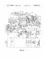
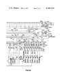


![`95385109 1%]?](http://vs1.manualzilla.com/store/data/005699459_1-7fc02fda0f8970d7c2f678aea00486d8-150x150.png)