1
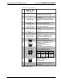
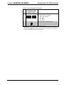
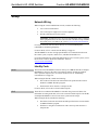
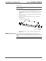
Crestron HD-MD8X1/HD-MD8X2 ® ® QuickSwitch HD HDMI Switcher Operations & Installation Guide Regulatory Compliance As of the date of manufacture, the HD-MD8X1 and HD-MD8X2 have been tested and found to comply with specifications for CE marking and standards per EMC and Radiocommunications Compliance Labelling. Federal Communications Commission (FCC) Compliance Statement This device complies with part 15 of the FCC Rules. Operation is subject to the following conditions: (1) This device may not cause harmful interference and (2) this device must accept any interference received, including interference that may cause undesired operation. CAUTION: Changes or modifications not expressly approved by the manufacturer responsible for compliance could void the user’s authority to operate the equipment. NOTE: This equipment has been tested and found to comply with the limits for a Class B digital device, pursuant to part 15 of the FCC Rules. These limits are designed to provide reasonable protection against harmful interference in a residential installation. This equipment generates, uses and can radiate radio frequency energy and, if not installed and used in accordance with the instructions, may cause harmful interference to radio communications. However, there is no guarantee that interference will not occur in a particular installation. If this equipment does cause harmful interference to radio or television reception, which can be determined by turning the equipment off and on, the user is encouraged to try to correct the interference by one or more of the following measures: Reorient or relocate the receiving antenna Increase the separation between the equipment and receiver Connect the equipment into an outlet on a circuit different from that to which the receiver is connected Consult the dealer or an experienced radio/TV technician for help Industry Canada (IC) Compliance Statement CAN ICES-3(B)/NMB-3(B) The specific patents that cover Crestron products are listed at patents.crestron.com. Crestron, the Crestron logo, Cresnet, Crestron e-Control, Crestron Studio, Crestron Toolbox, and QuickSwitch HD are either trademarks or registered trademarks of Crestron Electronics, Inc. in the United States and/or other countries. Blu-ray Disc is either a trademark or registered trademark of the Blu-ray Disc Association in the United States and/or other countries. Dolby and Dolby Digital are either trademarks or registered trademarks of Dolby Laboratories in the United States and/or other countries. DTS and DTS-HD Master Audio are either trademarks or registered trademarks of DTS, Inc. in the United States and/or other countries. HDMI and the HDMI Logo are either trademarks or registered trademarks of HDMI Licensing LLC in the United States and/or other countries. Other trademarks, registered trademarks, and trade names may be used in this document to refer to either the entities claiming the marks and names or their products. Crestron disclaims any proprietary interest in the marks and names of others. Crestron is not responsible for errors in typography or photography. This document was written by the Technical Publications department at Crestron. ©2013 Crestron Electronics, Inc. Crestron HD-MD8X1/HD-MD8X2 QuickSwitch HD HDMI Switcher Contents QuickSwitch HD HDMI Switcher: HD-MD8X1/HD-MD8X2 1 Introduction ............................................................................................................................... 1 Features and Functions ................................................................................................ 1 Applications................................................................................................................. 4 Internal Block Diagram ............................................................................................... 4 Specifications .............................................................................................................. 5 Physical Description.................................................................................................... 8 Setup ........................................................................................................................................ 12 Network Wiring......................................................................................................... 12 Identity Code ............................................................................................................. 12 Installation ................................................................................................................. 13 Hardware Hookup ..................................................................................................... 15 HDCP Signal Path ..................................................................................................... 15 EDID ......................................................................................................................... 17 Uploading and Upgrading........................................................................................................ 18 Establishing Communication..................................................................................... 18 Programs and Firmware ............................................................................................ 19 Program Checks ........................................................................................................ 20 Operation ................................................................................................................................. 21 Operating Modes ....................................................................................................... 21 View Mode................................................................................................................. 21 Route Mode ............................................................................................................... 22 Problem Solving ...................................................................................................................... 23 Troubleshooting......................................................................................................... 23 Check Network Wiring.............................................................................................. 23 Reference Documents................................................................................................ 24 Further Inquiries ........................................................................................................ 25 Future Updates .......................................................................................................... 25 Return and Warranty Policies .................................................................................................. 26 Merchandise Returns / Repair Service ...................................................................... 26 Crestron Limited Warranty........................................................................................ 26 Operations & Installation Guide – DOC. 6714B Contents i Crestron HD-MD8X1/HD-MD8X2 QuickSwitch HD HDMI Switcher QuickSwitch HD HDMI Switcher: HD-MD8X1/ HD-MD8X2 Introduction QuickSwitch HD® switchers from Crestron® enable high-performance HDMI® signal selection while delivering fast, trouble-free switching of all DVD and Blu-ray Disc® players, HDTV receivers, media servers, game consoles, multimedia computers, surround processors, and high-definition displays in a system. The HD-MD8X1 features eight HDMI inputs and a single HDMI output to feed a video display or processor. The HD-MD8X2 features eight HDMI inputs and two independently switchable HDMI outputs to feed two separate displays or to support a single display that has built-in PIP capability. For simplicity within this guide, the term “HD-MD8X1/2” is used except where noted. HDMI is the standard for interfacing high-definition AV equipment and is key to handling the latest HD video and audio formats. Providing unparalleled performance, functionality, and custom integration capability, the HD-MD8X1/2 supports HDMI with HDCP, Deep Color, and 3D, handling 1080p60 HD video and WUXGA computer resolutions as well as multichannel HD lossless audio. Features and Functions High-performance 8 x 1 or 8 x 2 HDMI switcher QuickSwitch HD switching technology Handles HDMI with Deep Color, 3D, and 7.1 linear PCM or high-bitrate encoded audio Compatible with DVI and DisplayPort Multimode* Supports video resolutions up to WUXGA 1920 x 1200 and HD 1080p60 Detects and reports detailed video and audio input information (Continued on following page) * HDMI IN requires an appropriate adapter or interface cable to accommodate a DVI or DisplayPort Multimode signal. HDMI OUT requires an appropriate adapter or interface cable to accommodate a DVI signal. CBL-HD-DVI interface cable sold separately. Operations & Installation Guide – DOC. 6714B QuickSwitch HD HDMI Switcher: HD-MD8X1/HD-MD8X2 1 QuickSwitch HD HDMI Switcher Crestron HD-MD8X1/HD-MD8X2 Features and Functions (Continued) Manages HDCP digital rights management for all connected devices Performs automatic AV signal format management via EDID HD-SCALER option (sold separately) ensures optimal image quality for all sources Includes front panel controls with security lockout Allows audio breakaway switching Simple setup and diagnostics via software Native control system integration via Ethernet or Cresnet® Single-space 19-inch rack-mountable QuickSwitch HD Technology Handling high-definition digital media means handling HDCP (High-bandwidth Digital Content Protection), the encryption scheme that content providers use to protect their DVDs, Blu-ray discs, and broadcast signals against unauthorized copying. Viewing HDCP encrypted content requires a source device to “authenticate” each display and signal processor in the system and issue each one a “key” before the content can be viewed. Ordinarily, this causes a complete loss of signal for up to 15 seconds each time a new source or display is selected anywhere in the system. In addition, every source device has a limited number of keys available; therefore, if too many displays are connected, the source stops outputting a signal without warning. Crestron QuickSwitch HD, however, manages the keys for every HDCP-compliant device in the system, maintaining continuous authentication for each device to ensure fast, reliable switching. EDID Format Management With HDMI comes a multitude of confusing video and audio formats to keep track of, and chances are that not every device in a system supports all of the same formats. The HD-MD8X1/2 eliminates any conflicts by managing the EDID (Extended Display Identification Data) that HDMI devices use to communicate their capabilities. Via Crestron Toolbox™ software, the format and resolution capabilities of each device can be assessed, allowing the installer to configure EDID signals appropriately for the most desirable and predictable behavior. Signal information such as resolution, frame rate, aspect ratio, color depth, and audio format can also be sent to the control system and displayed on a touch screen to allow custom functionality and enhanced diagnostics. High-Definition Scaler Option High-performance scaling capability can be added to the HD-MD8X1/2 using the optional HD-SCALER (sold separately). The HD-SCALER features fully automatic operation and is compact enough to install at the display location, ensuring an optimal image regardless of the source that is selected. It also provides analog video and audio inputs to accommodate additional analog sources. 2 QuickSwitch HD HDMI Switcher: HD-MD8X1/HD-MD8X2 Operations & Installation Guide – DOC. 6714B Crestron HD-MD8X1/HD-MD8X2 QuickSwitch HD HDMI Switcher Computer Compatibility Besides handling every available HD format supported by HDMI, the HD-MD8X1/2 also supports computer resolutions up to 1920 x 1200 WUXGA, and is compatible with DVI and DisplayPort Multimode computer signals using a suitable adapter or dongle*. Audio Breakaway Audio signals may be routed independently of video in the HD-MD8X1/2, allowing listening to one source while viewing another. For instance, listening to favorite music from a media server is possible while playing a video game or surfing the Internet on screen. Front Panel Controls The HD-MD8X1/2 works out of the box without requiring any connection to a control system or computer, providing intuitive signal switching via its front panel. The front panel is great for everyday use, or may be used just for initial system testing. Front panel buttons may be locked out to prevent unauthorized tampering or accidental switching, while the LED indicators remain active to show signal routing status. The input and output controls can be labeled easily using Crestron Engraver software or standard 3/8" (10 mm) tape labels. Native Crestron Control Via the choice of Cresnet® or high-speed Ethernet, the HD-MD8X1/2 allows direct communication with a Crestron control system for a fully integrated signal routing solution as part of any high-end home theater, boardroom, classroom, or command center system. Easy Setup Despite its many powerful features and capabilities, the HD-MD8X1/2 is simple to set up using Crestron Toolbox software. The Toolbox setup tool allows the installer to view information about each HDMI device and easily make intelligent choices to ensure a reliable system setup. * HDMI IN requires an appropriate adapter or interface cable to accommodate a DVI or DisplayPort Multimode signal. HDMI OUT requires an appropriate adapter or interface cable to accommodate a DVI signal. CBL-HD-DVI interface cable sold separately. Operations & Installation Guide – DOC. 6714B QuickSwitch HD HDMI Switcher: HD-MD8X1/HD-MD8X2 3 QuickSwitch HD HDMI Switcher Crestron HD-MD8X1/HD-MD8X2 Applications The following diagram shows an HD-MD8X2 in a residential application. HD-MD8X2 in a Residential Application Internal Block Diagram The following diagram represents the switching abilities of the HD-MD8X1/2. Internal Block Diagram of the HD-MD8X1/2 Digital Video Switch HDMI RX (8) HDMI TX (1 or 2) Digital Audio Switch 4 QuickSwitch HD HDMI Switcher: HD-MD8X1/HD-MD8X2 Operations & Installation Guide – DOC. 6714B Crestron HD-MD8X1/HD-MD8X2 QuickSwitch HD HDMI Switcher Specifications Specifications for the HD-MD8X1/2 are listed in the following table. HD-MD8X1/2 Specifications SPECIFICATION DETAILS Video HD-MD8X1: 8 x 1 digital matrix, resolution management, Crestron QuickSwitch HD Switcher HD-MD8X2: 8 x 2 digital matrix, resolution management, Crestron QuickSwitch HD Input Signal Types HDMI, DVI*, DisplayPort Multimode* Output Signal Types HDMI, DVI* Formats HDMI with Deep Color and 3D, DVI, HDCP content protection support Input Resolutions Progressive 640 x 480 @ 60 Hz 720 x 480 @ 60 Hz (480p) 720 x 576 @ 50 Hz (576p) 800 x 600 @ 60 Hz 848 x 480 @ 60 Hz 852 x 480 @ 60 Hz 854 x 480 @ 60 Hz 1024 x 768 @ 60 Hz 1024 x 852 @ 60 Hz 1024 x 1024 @ 60 Hz 1280 x 720 @ 50 Hz (720p50) 1280 x 720 @ 60 Hz (720p60) 1280 x 768 @ 60 Hz 1280 x 800 @ 60 Hz 1280 x 960 @ 60 Hz 1280 x 1024 @ 60 Hz 1360 x 768 @ 60 Hz 1365 x 1024 @ 60 Hz 1366 x 768 @ 60 Hz 1400 x 1050 @ 60 Hz 1440 x 900 @ 60 Hz 1600 x 900 @ 60 Hz 1600 x 1200 @ 60 Hz 1680 x 1050 @ 60 Hz 1920 x 1080 @ 24 Hz (1080p24) 1920 x 1080 @ 25 Hz (1080p25) 1920 x 1080 @ 50 Hz (1080p50) 1920 x 1080 @ 60 Hz (1080p60) 1920 x 1200 @ 60 Hz 2048 x 1080 @ 24 Hz 2048 x 1152 @ 60 Hz plus any other resolution allowed by HDMI up to 165 MHz pixel clock Interlaced 720 x 480 @ 30 Hz (480i) 720 x 576 @ 25 Hz (576i) 1920 x 1080 @ 25 Hz (1080i25) 1920 x 1080 @ 30 Hz (1080i30) plus any other resolution allowed by HDMI up to 165 MHz pixel clock (Continued on following page) Operations & Installation Guide – DOC. 6714B QuickSwitch HD HDMI Switcher: HD-MD8X1/HD-MD8X2 5 QuickSwitch HD HDMI Switcher Crestron HD-MD8X1/HD-MD8X2 HD-MD8X1/2 Specifications (Continued) SPECIFICATION DETAILS Video (Continued) Output Resolutions Matched to inputs Audio Switcher HD-MD8X1: 8 x 1 digital multichannel switching, audio-follow-video or breakaway HD-MD8X2: 8 x 2 digital multichannel switching, audio-follow-video or breakaway Input Signal Types HDMI, DisplayPort Multimode* Output Signal Type HDMI Formats Dolby Digital®, Dolby Digital EX, Dolby Digital Plus, Dolby® TrueHD, DTS®, DTS-ES, DTS 96/24, DTS-HD High Res, DTS-HD Master Audio™, up to 8 channel PCM Communications Ethernet For control and console; 10/100 Mbps, auto-switching, auto-negotiating, auto-discovery, full/half duplex, DHCP Cresnet For control and console, Cresnet slave USB For console, USB 2.0 client HDMI Provides EDID and HDCP key management Power Cresnet Power Usage HD-MD8X1: 26 W (1.09 A @ 24 Vdc) HD-MD8X2: 27 W (1.13 A @ 24 Vdc) Default Net ID 9B Environmental Temperature 32º to 104º F (0º to 40º C) Humidity 10% to 90% RH (non-condensing) Heat Dissipation 92 Btu/h Enclosure Chassis Metal, black finish, convection-cooled, vented top and sides Faceplate Metal, black finish with polycarbonate label overlay Mounting Freestanding or 1 U 19-inch rack-mountable (adhesive feet and rack ears included) Dimensions Height 1.70 in (44 mm) without feet; 1.80 in (46 mm) with feet Width 17.03 in (433 mm) without ears; 19.00 in (483 mm) with ears Depth 10.06 in (256 mm) Weight 4.1 lb (1.9 kg) (Continued on following page) 6 QuickSwitch HD HDMI Switcher: HD-MD8X1/HD-MD8X2 Operations & Installation Guide – DOC. 6714B Crestron HD-MD8X1/HD-MD8X2 QuickSwitch HD HDMI Switcher HD-MD8X1/2 Specifications (Continued) SPECIFICATION DETAILS Available Accessories * CBL-HD Crestron Certified HDMI Interface Cable CBL-HD-DVI Crestron Certified HDMI to DVI Interface Cable CBL-HD-LOCK Locking High-Speed HDMI Cable DMCI DigitalMedia Card Interface HD-DA-2 1-to-2 HDMI Distribution Amplifier and Audio Converter HD-EXT1-C HDMI over Shielded Twisted Pair Extender HD-EXT2-C HDMI over Shielded Twisted Pair Extender HD-RX1-F HDMI over Fiber Receiver HD-RX3-F HDMI over Fiber Receiver HD-SCALER High-Definition Video Scaler HD-TX1-F HDMI over Fiber Transmitter HD-TX3-F HDMI over Fiber Transmitter HDMI IN requires an appropriate adapter or interface cable to accommodate a DVI or DisplayPort Multimode signal. HDMI OUT requires an appropriate adapter or interface cable to accommodate a DVI signal. CBL-HD-DVI interface cable sold separately. Operations & Installation Guide – DOC. 6714B QuickSwitch HD HDMI Switcher: HD-MD8X1/HD-MD8X2 7 QuickSwitch HD HDMI Switcher Crestron HD-MD8X1/HD-MD8X2 Physical Description This section provides information on the connections, controls, and indicators available on the HD-MD8X1/2. HD-MD8X1 Physical Views (Front and Rear) HD-MD8X2 Physical Views (Front and Rear) 8 QuickSwitch HD HDMI Switcher: HD-MD8X1/HD-MD8X2 Operations & Installation Guide – DOC. 6714B Crestron HD-MD8X1/HD-MD8X2 QuickSwitch HD HDMI Switcher HD-MD8X1/2 Overall Dimensions (HD-MD8X2 Shown) 9.75 in (248 mm) 10.06 in (256 mm) 17.03 in (433 mm) 1.70 in (44 mm) HD-MD8X1/2 Connectors, Controls, and Indicators (HD-MD8X2 Shown) 1 2 4 3 6 5 8 9 7 10 Operations & Installation Guide – DOC. 6714B 11 12 13 14 15 16 QuickSwitch HD HDMI Switcher: HD-MD8X1/HD-MD8X2 9 QuickSwitch HD HDMI Switcher Crestron HD-MD8X1/HD-MD8X2 Connectors, Controls, and Indicators # CONNECTORS1, CONTROLS, AND INDICATORS 1 PWR LED (1) Green LED, indicates 24 Vdc power supplied from Cresnet control network 2 NET LED (1) Amber LED, indicates communication with Cresnet system 3 SYNC (Button and LED) (1) Recessed push button and red LED, selects Sync mode for viewing input signal sensing 4 VIEW (Button and LED) (1) Push button and red LED, selects View mode for viewing current routes 5 ROUTE (Button and LED) (1) Push button and red LED, selects Route mode to allow routing changes 6 A (Button and LED) (1) Push button and red LED, selects audio routing view 7 V (Button and LED) (1) Push button and red LED, selects video routing view 8 IN 1-8 (Buttons and LEDs) (8) Push buttons and red LEDs, select input for routing 9 OUT 1/OUT 1-2 (Buttons and LEDs) HD-MD8X1 (1) or HD-MD8X2 (2) push buttons and red LEDs, select output for routing 10 INPUT 1-8 11 OUTPUT 1/ OUTPUT 1-2 HD-MD8X1 (1) or HD-MD8X2 (2) 19-pin Type A HDMI female; HDMI digital video/audio outputs; Supports DVI2 LAN (1) 8-pin RJ-45 with two LED indicators; 10BASE-T/100BASE-TX Ethernet port, Green LED indicates link status; Amber LED indicates Ethernet activity 12 Green LED Pin 8 Amber LED Pin 1 13 COMPUTER 14 SETUP (Button and LED) DESCRIPTION (8) 19-pin Type A HDMI female; HDMI digital video/audio inputs; Supports DVI and DisplayPort Multimode2 PIN SIGNAL PIN SIGNAL 1 2 3 4 TX + TX RC + N/C 5 6 7 8 N/C RC N/C N/C (1) USB Type B female; USB 2.0 computer console port (6 ft cable included) (1) Miniature push button and red LED, used for touch-settable ID (TSID) and Ethernet autodiscovery (Continued on following page) 10 QuickSwitch HD HDMI Switcher: HD-MD8X1/HD-MD8X2 Operations & Installation Guide – DOC. 6714B Crestron HD-MD8X1/HD-MD8X2 QuickSwitch HD HDMI Switcher Connectors, Controls, and Indicators (Continued) # CONNECTORS1, CONTROLS, AND INDICATORS NET 15 24 Y Z G 24 Y Z G DESCRIPTION (2) 4-pin 3.5 mm detachable terminal blocks; Cresnet slave ports, paralleled 24: Y: Z: G: 16 G Power (24 Vdc) Data Data Ground (1) 6-32 screw, chassis ground lug 1. Interface connectors for the NET ports are provided with the unit. 2. HDMI IN requires an appropriate adapter or interface cable to accommodate a DVI or DisplayPort Multimode signal. HDMI OUT requires an appropriate adapter or interface cable to accommodate a DVI signal. CBL-HD-DVI interface cable sold separately. Operations & Installation Guide – DOC. 6714B QuickSwitch HD HDMI Switcher: HD-MD8X1/HD-MD8X2 11 QuickSwitch HD HDMI Switcher Crestron HD-MD8X1/HD-MD8X2 Setup Network Wiring When wiring the Cresnet and Ethernet network, consider the following: Use Crestron Certified Wire. Use Crestron power supplies for Crestron equipment. Provide sufficient power to the system. CAUTION: Insufficient power can lead to unpredictable results or damage to the equipment. Please use the Crestron Power Calculator to help calculate how much power is needed for the system (www.crestron.com/calculators). For Cresnet networks with 20 or more devices, use a Cresnet Hub/Repeater (CNXHUB) to maintain signal quality. For more details, refer to “Check Network Wiring” on page 23. The HD-MD8X1/2 can also use high-speed Ethernet for communications between the control system, computer, media server, and other IP-based devices. For general information on connecting Ethernet devices in a Crestron system, refer to the Crestron e-Control Reference Guide (Doc. 6052) at www.crestron.com/manuals. Identity Code Net ID The Net ID of the HD-MD8X1/2 has been factory set to 9B. The Net IDs of multiple HD-MD8X1/2 devices in the same system must be unique. Net IDs are changed from a personal computer (PC) via Crestron Toolbox (refer to “Establishing Communication” on page 18). When setting the Net ID, consider the following: The Net ID of each unit must match an ID code specified in the Crestron Studio™ or SIMPL Windows program. Each network device must have a unique Net ID. For more details, refer to the Crestron Toolbox help file. IP ID The IP ID is set within the HD-MD8X1/2’s IP table using Crestron Toolbox. For information on setting an IP table, refer to the Crestron Toolbox help file. The IP IDs of multiple HD-MD8X1/2 devices in the same system must be unique. When setting the IP ID, consider the following: The IP ID of each unit must match an IP ID specified in the Crestron Studio or SIMPL Windows program. Each device using IP to communicate with a control system must have a unique IP ID. 12 QuickSwitch HD HDMI Switcher: HD-MD8X1/HD-MD8X2 Operations & Installation Guide – DOC. 6714B Crestron HD-MD8X1/HD-MD8X2 QuickSwitch HD HDMI Switcher Installation Ventilation The HD-MD8X1/2 should be used in a well-ventilated area. The venting holes should not be obstructed under any circumstances. To prevent overheating, do not operate this product in an area that exceeds the environmental temperature range listed in the table of specifications. Consider using forced air ventilation and/or incrementing the spacing between units to reduce overheating. Contact with thermal insulating materials should be avoided on all sides of the unit. Rack Mounting The HD-MD8X1/2 can be mounted in a rack or stacked with other equipment. Two “ears” are provided with the HD-MD8X1/2 for rack mounting. These ears must be installed prior to mounting. Complete the following procedure to attach the ears to the unit. The only tool required is a #2 Phillips screwdriver. WARNING: To prevent bodily injury when mounting or servicing this unit in a rack, observe the following guidelines: When mounting this unit in a partially filled rack, load the rack from the bottom to the top with the heaviest component at the bottom of the rack. If the rack is provided with stabilizing devices, install the stabilizers before mounting or servicing the unit in the rack. NOTE: Observe the following guidelines when installing equipment in a rack: Elevated Operating Ambient Temperature - If installed in a closed or multi-unit rack assembly, the operating ambient temperature of the rack environment may be greater than room ambient temperature. Therefore, consideration should be given to installing the equipment in an environment compatible with the maximum ambient temperature (Tma) specified by the manufacturer. Reduced Air Flow - Installation of the equipment in a rack should be such that the amount of airflow required for safe operation of the equipment is not compromised. Mechanical Loading - Mounting of the equipment in the rack should be such that a hazardous condition is not achieved due to uneven mechanical loading. Circuit Overloading - Consideration should be given to the connection of the equipment to the supply circuit and the effect that overloading of the circuits might have on overcurrent protection and supply wiring. Appropriate consideration of equipment nameplate ratings should be used when addressing this concern. Reliable Earthing - Reliable earthing of rack-mounted equipment should be maintained. Particular attention should be given to supply connections other than direct connections to the branch circuit (e.g., use of power strips). NOTE: If rack mounting is not required, rubber feet are provided for tabletop mounting or stacking. Apply the feet near the corner edges on the underside of the unit. Operations & Installation Guide – DOC. 6714B QuickSwitch HD HDMI Switcher: HD-MD8X1/HD-MD8X2 13 QuickSwitch HD HDMI Switcher Crestron HD-MD8X1/HD-MD8X2 To install the ears: CAUTION: To prevent equipment damage, use only the rack ears Crestron provides for this device. 1. There are screws that secure each side of the HD-MD8X1/2 top cover. Using a #2 Phillips screwdriver, remove the three screws closest to the front panel from one side of the unit. Refer to the diagram following step 3 for a detailed view. 2. Position a rack ear so that its mounting holes align with the holes vacated by the screws in step 1. 3. Secure the ear to the unit with three screws from step 1 as shown in the following diagram. Ear Attachment for Rack Mounting Use Cover Screws 4. Stacking Repeat procedure (steps 1 through 3) to attach the remaining ear to the opposite side. Four “feet” are provided with the HD-MD8X1/2 so that if the unit is not rack mounted, the rubber feet can provide stability when the unit is placed on a flat surface or stacked. These feet should be attached near the corners prior to the hookup procedure. NOTE: No more than two HD-MD8X1/2 units should be stacked. 14 QuickSwitch HD HDMI Switcher: HD-MD8X1/HD-MD8X2 Operations & Installation Guide – DOC. 6714B Crestron HD-MD8X1/HD-MD8X2 QuickSwitch HD HDMI Switcher Hardware Hookup Connect the Device Make the necessary connections as called out in the illustration that follows this paragraph. Refer to “Network Wiring” on page 12 before attaching the 4-position terminal block connectors. Apply power after all connections have been made. Hardware Connections for the HD-MD8X1/2 (HD-MD8X2 Shown) Ground INPUT: From HDMI Sources OUTPUT 1-2: To HDMI Receiver or Display COMPUTER: To USB Port on PC NET: Power from Cresnet Power Supply and to Cresnet Devices LAN: 10BASE-T/ 100BASE-TX Ethernet to LAN NOTE: Ensure that the unit is properly grounded by connecting the chassis ground lug to an earth ground (building steel). NOTE: To prevent overheating, do not operate this product in an area that exceeds the environmental temperature range listed in the table of specifications. Label the Buttons Use Crestron Engraver software to print custom labels for the HD-MD8X1/2’s front panel buttons and LEDs. Crestron recommends printing on 100-pound paper. Paper weighing less than 100 pounds tends to crumple while sliding in, while paper weighing more than 100 pounds may not fit. HDCP Signal Path Sources using HDCP limit the number of display devices it can transmit to while simultaneously limiting the depth of devices in the signal path. Too many devices or greater than the allowed depth in a signal path (from source to display) may create problems with the display of audio and video content. The HDCP specification states that the maximum depth of devices between source and display is six. Examples are provided in the following diagram. Operations & Installation Guide – DOC. 6714B QuickSwitch HD HDMI Switcher: HD-MD8X1/HD-MD8X2 15 QuickSwitch HD HDMI Switcher Crestron HD-MD8X1/HD-MD8X2 Examples of Reported HDCP Devices and Reported HDCP Depth Device # 2 Device # 1 Blu-ray Player 2 HDCP Devices Reported Depth = 1 Blu-ray Player 3 HDCP Devices Reported Depth = 1 HD-MD8X1/2 Switcher HDMI Reported Depth = 1 Reported Depth = 0 Device # 1 Device # 2 HD-MD8X2 Switcher HDMI Display Using HDMI with HDCP HDMI Display Using HDMI with HDCP HDMI Reported Depth = 1 Reported Depth = 0 Device # 3 Display Using HDMI with HDCP HDMI Reported Depth = 0 Device # 1 3 HDCP Devices Reported Depth = 2 Blu-ray Player HDMI Device # 2 HD-MD8X1/2 HDMI AV Receiver with HDCP Reported Depth = 2 Reported Depth = 1 Device # 1 4 HDCP Devices Reported Depth = 2 Blu-ray Player HDMI Device # 3 HDMI Display Using HDMI with HDCP Reported Depth = 0 Device # 2 HD-MD8X2 Display Using HDMI with HDCP HDMI Reported Depth = 2 Device # 3 Device # 4 HDMI AV Receiver Reported Depth = 1 HDMI Reported Depth = 0 Display Using HDMI with HDCP Reported Depth = 0 Using Crestron Toolbox, the switcher can test HDMI sources and displays for switching limitations due to HDCP keys. The number of HDCP keys specifies the number of display devices that can be connected to a source over HDMI using HDCP authentication. For more information, refer to the Crestron Toolbox help file. 16 QuickSwitch HD HDMI Switcher: HD-MD8X1/HD-MD8X2 Operations & Installation Guide – DOC. 6714B Crestron HD-MD8X1/HD-MD8X2 QuickSwitch HD HDMI Switcher EDID EDID is a data structure that HDMI receivers use to indicate their capabilities to the HDMI sources. The HD-MD8X1/2 routes HDMI signals from any of the eight video inputs to one or two (HD-MD8X2 only) output channels. According to the HDMI standard, HDMI sources are expected to only deliver audio and video formats that are supported by the destination. To configure video/audio EDID, use the DMTool in Crestron Toolbox. The DMTool allows the EDID configuration to be set manually while ensuring that the EDID is accurate. For detailed information about configuring video/audio EDID, refer to the Crestron Toolbox help file. Operations & Installation Guide – DOC. 6714B QuickSwitch HD HDMI Switcher: HD-MD8X1/HD-MD8X2 17 QuickSwitch HD HDMI Switcher Crestron HD-MD8X1/HD-MD8X2 Uploading and Upgrading Crestron recommends using the latest programming software and that each device contains the latest firmware to take advantage of the most recently released features. However, before attempting to upload or upgrade, it is necessary to establish communication. Once communication has been established, files (for example, programs or firmware) can be transferred to the control system (or device). Finally, program checks can be performed (such as changing the device ID or creating an IP table) to ensure proper functioning. NOTE: Crestron software and any files on the Web site are for authorized Crestron dealers and Crestron Service Providers (CSPs) only. New users must register to obtain access to certain areas of the site (including the FTP site). Establishing Communication Use Crestron Toolbox for communicating with the HD-MD8X1/2; refer to the Crestron Toolbox help file for details. There are three methods of communication: indirect, USB, and TCP/IP. Indirect Indirect Communication Serial, Control System HD-MD8X1/2 Cresnet N LA NET 24 Y or USB 24 YZ ZG G SETUP 3 COMP MC UTER LAN IVITY ACT T OUTPU 1 8 UIRE 7 ACQ HWER PUT COM R SW- 6 R INPUT 5 4 NET PWR 3 , NJ LEIGH 2 1 ELEC TRON ICS INC., 07647 ROCK PC Running Crestron Toolbox HD-MD8X1/2 connects to control system via Cresnet: USB 1. Click Tools | System Info. 2. Click the 3. For Connection Type, select Cresnet ID. In the Through drop-down menu, select the control system. 4. Click OK. Communications are confirmed when the device information is displayed. icon. NOTE: Required for initial setup of Ethernet parameters. USB Communication HD-MD8X1/2 USB NET 24 Y 24 YZ ZG G SETUP UTER COMP LAN T OUTPU 1 8 7 6 INPUT 5 4 3 , NJ LEIGH 2 1 ELEC TRON ICS INC., 07647 ROCK PC Running Crestron Toolbox 18 QuickSwitch HD HDMI Switcher: HD-MD8X1/HD-MD8X2 Operations & Installation Guide – DOC. 6714B Crestron HD-MD8X1/HD-MD8X2 QuickSwitch HD HDMI Switcher The COMPUTER port on the HD-MD8X1/2 connects to the USB port on the PC via the included Type A to Type B USB cable: TCP/IP 1. Click Tools | System Info. 2. Click the 3. For Connection Type, select USB. When multiple USB devices are connected, identify the HD-MD8X1/2 by entering “HD-MD8X1” or “HD-MD8X2” in the Model text box, the unit’s serial number in the Serial text box or the unit’s hostname (if known) in the Hostname text box. 4. Click OK. Communications are confirmed when the device information is displayed. icon. Ethernet Communication HD-MD8X1/2 AN L NET 24 Y 24 YZ ZG G SETUP UTER COMP LAN T OUTPU 1 8 7 6 INPUT 5 4 3 , NJ LEIGH 2 1 ELEC TRON ICS INC., 07647 ROCK PC Running Crestron Toolbox The HD-MD8X1/2 connects to a PC via Ethernet: 1. Use the Device Discovery Tool (click the icon) in Crestron Toolbox to detect all Ethernet devices on the network and their IP configuration. The tool is available in Toolbox version 1.15.143 or later. 2. Click the HD-MD8X1/2 to display information about the device. Programs and Firmware Program or firmware files may be distributed from programmers to installers or from Crestron to dealers. Firmware upgrades are available from the Crestron Web site as new features are developed after product releases. One has the option to upload programs via the programming software or to upload and upgrade via the Crestron Toolbox. For details on uploading and upgrading, refer to the Crestron Studio help file, SIMPL Windows help file, or the Crestron Toolbox help file. Crestron Studio / SIMPL Windows If a Crestron Studio (or SIMPL Windows) program is provided, it can be uploaded to the control system using Crestron Studio (or SIMPL Windows) or Crestron Toolbox. Firmware Check the Crestron Web site to find the latest firmware. (New users must register to obtain access to certain areas of the site, including the FTP site.) Upgrade HD-MD8X1/2 firmware using Crestron Toolbox: 1. Download the appropriate .puf file from the Crestron Web site to a PC. 2. Double-click the .puf file. The Toolbox Address Book opens. 3. From the list in the Address Book, select the entry listed for the HD-MD8X1/2, and then click OK. The HD device list is displayed, and the checkbox of the HD-MD8X1/2 firmware is automatically selected. 4. Click Update. 5. After the process is complete, click Recheck to verify the upgrade. Operations & Installation Guide – DOC. 6714B QuickSwitch HD HDMI Switcher: HD-MD8X1/HD-MD8X2 19 QuickSwitch HD HDMI Switcher Crestron HD-MD8X1/HD-MD8X2 Program Checks Actions that can be performed on the HD-MD8X1/2 vary depending on whether it is connected via Cresnet or Ethernet. Cresnet Connections For Cresnet connections, using Crestron Toolbox, display the network device tree (Tools | Network Device Tree View) to show all network devices connected to the control system. Right-click on the HD-MD8X1/2 to display actions that can be performed on the HD-MD8X1/2. Ethernet Connections For Ethernet connections, using Crestron Toolbox, display the “System Info” window (Tools | System Info) and select the Functions menu to display actions that can be performed on the HD-MD8X1/2. Be sure to use Crestron Toolbox to create the HD-MD8X1/2’s IP table. 1. Select Functions | IP Table Setup. 2. Add, modify, or delete entries in the IP table. The HD-MD8X1/2 can have only one IP table entry. 3. A defined IP table can be saved to a file or sent to the device. Edit the control system’s IP table to include an entry for the HD-MD8X1/2. The entry should list the HD-MD8X1/2’s IP ID (specified on the HD-MD8X1/2’s IP table) and the internal gateway IP address 127.0.0.1. 20 QuickSwitch HD HDMI Switcher: HD-MD8X1/HD-MD8X2 Operations & Installation Guide – DOC. 6714B Crestron HD-MD8X1/HD-MD8X2 QuickSwitch HD HDMI Switcher Operation Operating Modes The HD-MD8X1/2 can operate in the Sync, View, or Route mode. Sync Mode The Sync mode uses the front panel controls to view the presence of video signals on each input. Press the SYNC button to activate the Sync mode. The SYNC LED lights as well as the LEDs of any inputs with a video signal present. View Mode The View mode uses the front panel controls to view routing information for inputs and output(s). Routing information for audio, video, and USB portions of an input can be viewed independently. For more information, refer to “View Mode” below. Route Mode The Route mode uses the front panel controls to route input signals to output(s). Press the ROUTE button to activate the Route mode. When in the Route mode, pressing an input button shows the output(s) that are connected to the input. Audio and video portions of an input can be routed independently. For more information, refer to “Route Mode” on page 22. View Mode Use the View mode to view routing information for inputs and output(s). To select the View mode, press the VIEW button. The VIEW LED lights. View Source Routing View Output Routing 1. Press an input signal button to display the output(s) that are connected to it. 2. Press A or V to see where the audio or video portion of an input signal is routed. 1. Press an output signal button to display the input signal that is connected. NOTE: If the other output on an HD-MD8X2 is connected to the same input, its LED also lights. 2. Press A or V to see the input that is providing the audio or video portion of the output signal. Operations & Installation Guide – DOC. 6714B QuickSwitch HD HDMI Switcher: HD-MD8X1/HD-MD8X2 21 QuickSwitch HD HDMI Switcher Crestron HD-MD8X1/HD-MD8X2 Route Mode Signals coming into the switcher can be switched to the output(s). Additionally, the audio and video portions of an input signal can be switched simultaneously or separately. To enter the Route mode, press the ROUTE button. The ROUTE LED lights. Switch Audio and Video Simultaneously 1. Press the A and V buttons to select the audio and video portions for switching. The respective LEDs light. NOTE: If an output has different audio or video portions, a new route causes the audio portion on the output to switch to the newly selected video input. Switch Audio and Video Separately 2. Press the button corresponding to the input to be switched. The LED of the selected input lights. To turn off an output, deselect the input. 3. Press the button(s) corresponding to the output(s) to be switched. The LED(s) of the selected output(s) light and the new route is connected. 4. Repeat for any other routes to be changed. 1. Press the A or V buttons to select the audio or video portions to be switched. The respective LEDs light. 2. Press the button corresponding to the input to be switched. The LED of the selected input lights. To turn off an output, deselect the input. 3. Press the button(s) corresponding to the output(s) to be switched. The LED(s) of the selected output(s) light. 4. Repeat for any other routes to be changed. 22 QuickSwitch HD HDMI Switcher: HD-MD8X1/HD-MD8X2 Operations & Installation Guide – DOC. 6714B Crestron HD-MD8X1/HD-MD8X2 QuickSwitch HD HDMI Switcher Problem Solving Troubleshooting The following table provides corrective action for possible trouble situations. If further assistance is required, please contact a Crestron customer service representative. HD-MD8X1/2 Troubleshooting TROUBLE POSSIBLE CAUSE(S) CORRECTIVE ACTION Device is not communicating with the network. Use Crestron Toolbox to poll the network. Verify network connection to the device. Device is not receiving power from a Crestron power source. Use a Crestron power source. Verify connections. Device is not receiving sufficient power. Use the Crestron Power Calculator to help calculate how much power is needed for the system. PWR LED does not illuminate. Switcher is not receiving power. Verify that cables plugged into the NET ports are secure. NET LED does not illuminate. Cresnet connection is not used. Use a Cresnet connection. Net ID is not set to match the Net ID in the Crestron Studio or SIMPL Windows program. Using Crestron Toolbox, poll the network. Verify that the Net ID for the switcher is set to match the ID specified in the Crestron Studio or SIMPL Windows program. Incorrect audio or video displayed. Audio is routed separately from video. Reroute audio together with video. Distorted audio or video. Source does not match capabilities of destination. Use Crestron Toolbox to manage EDID capabilities of devices in the system. Loss of functionality due to electrostatic discharge. Improper grounding. Check that all ground connections have been made properly. Device does not function. Check Network Wiring Use the Right Wire To ensure optimum performance over the full range of the installation topology, use Crestron Certified Wire only. Failure to do so may incur additional charges if support is required to identify performance deficiencies because of using improper wire. Operations & Installation Guide – DOC. 6714B QuickSwitch HD HDMI Switcher: HD-MD8X1/HD-MD8X2 23 QuickSwitch HD HDMI Switcher Calculate Power Crestron HD-MD8X1/HD-MD8X2 CAUTION: Use only Crestron power supplies for Crestron equipment. Failure to do so could cause equipment damage or void the Crestron warranty. CAUTION: Provide sufficient power to the system. Insufficient power can lead to unpredictable results or damage to the equipment. Please use the Crestron Power Calculator to help calculate how much power is needed for the system (www.crestron.com/calculators). When calculating the length of wire for a particular Cresnet run, the wire gauge and the Cresnet power usage of each network unit to be connected must be taken into consideration. Use Crestron Certified Wire only. If Cresnet units are to be daisy chained on the run, the Cresnet power usage of each network unit to be daisy chained must be added together to determine the Cresnet power usage of the entire chain. If the unit is home-run from a Crestron system power supply network port, the Cresnet power usage of that unit is the Cresnet power usage of the entire run. The wire gauge and the Cresnet power usage of the run should be used in the following equation to calculate the cable length value on the equation’s left side. Cable Length Equation 40,000 L< RxP Where: L = Length of run (or chain) in feet R = 6 Ohms (Crestron Certified Wire: 18 AWG (0.75 MM 2 )) or 1.6 Ohms (Cresnet HP: 12 AWG (4 MM 2 )) P = Cresnet power usage of entire run (or chain) Make sure the cable length value is less than the value calculated on the right side of the equation. For example, a Cresnet run using 18 AWG Crestron Certified Wire and drawing 20 watts should not have a length of run more than 333 feet (101 meters). If Cresnet HP is used for the same run, its length could extend to 1250 feet (381 meters). NOTE: All Crestron certified Cresnet wiring must consist of two twisted pairs. One twisted pair is the 24 and G pair and the other twisted pair is the Y and Z pair. Strip and Tin Wire When daisy chaining Cresnet units, strip the ends of the wires carefully to avoid nicking the conductors. Twist together the ends of the wires that share a pin on the network connector and tin the twisted connection. Apply solder only to the ends of the twisted wires. Avoid tinning too far up the wires or the end becomes brittle. Insert the tinned connection into the Cresnet connector and tighten the retaining screw. Repeat the procedure for the other three conductors. Add Hubs Use of a Cresnet Hub/Repeater (CNXHUB) is advised whenever the number of Cresnet devices on a network exceeds 20 or when the combined total length of Cresnet cable exceeds 3000 feet (914 meters). Reference Documents The document mentioned in this guide is available at www.crestron.com/manuals. Related Reference Document DOCUMENT TITLE Crestron e-Control Reference Guide 24 QuickSwitch HD HDMI Switcher: HD-MD8X1/HD-MD8X2 Operations & Installation Guide – DOC. 6714B Crestron HD-MD8X1/HD-MD8X2 QuickSwitch HD HDMI Switcher Further Inquiries To locate specific information or resolve questions after reviewing this guide, contact Crestron's True Blue Support at 1-888-CRESTRON [1-888-273-7876] or, for assistance within a particular geographic region, refer to the listing of Crestron worldwide offices at www.crestron.com/offices. To post a question about Crestron products, log onto Crestron’s Online Help at www.crestron.com/onlinehelp. First-time users must establish a user account to fully benefit from all available features. Future Updates As Crestron improves functions, adds new features and extends the capabilities of the HD-MD8X1/2, additional information may be made available as manual updates. These updates are solely electronic and serve as intermediary supplements prior to the release of a complete technical documentation revision. Check the Crestron Web site periodically for manual update availability and its relevance. Updates are identified as an “Addendum” in the Download column. Operations & Installation Guide – DOC. 6714B QuickSwitch HD HDMI Switcher: HD-MD8X1/HD-MD8X2 25 QuickSwitch HD HDMI Switcher Crestron HD-MD8X1/HD-MD8X2 Return and Warranty Policies Merchandise Returns / Repair Service 1. No merchandise may be returned for credit, exchange or service without prior authorization from Crestron. To obtain warranty service for Crestron products, contact an authorized Crestron dealer. Only authorized Crestron dealers may contact the factory and request an RMA (Return Merchandise Authorization) number. Enclose a note specifying the nature of the problem, name and phone number of contact person, RMA number and return address. 2. Products may be returned for credit, exchange or service with a Crestron Return Merchandise Authorization (RMA) number. Authorized returns must be shipped freight prepaid to Crestron, 6 Volvo Drive, Rockleigh, N.J. or its authorized subsidiaries, with RMA number clearly marked on the outside of all cartons. Shipments arriving freight collect or without an RMA number shall be subject to refusal. Crestron reserves the right in its sole and absolute discretion to charge a 15% restocking fee plus shipping costs on any products returned with an RMA. 3. Return freight charges following repair of items under warranty shall be paid by Crestron, shipping by standard ground carrier. In the event repairs are found to be non-warranty, return freight costs shall be paid by the purchaser. Crestron Limited Warranty Crestron Electronics, Inc. warrants its products to be free from manufacturing defects in materials and workmanship under normal use for a period of three (3) years from the date of purchase from Crestron, with the following exceptions: disk drives and any other moving or rotating mechanical parts, pan/tilt heads and power supplies are covered for a period of one (1) year; touch screen display and overlay components are covered for 90 days; batteries and incandescent lamps are not covered. This warranty extends to products purchased directly from Crestron or an authorized Crestron dealer. Purchasers should inquire of the dealer regarding the nature and extent of the dealer's warranty, if any. Crestron shall not be liable to honor the terms of this warranty if the product has been used in any application other than that for which it was intended or if it has been subjected to misuse, accidental damage, modification or improper installation procedures. Furthermore, this warranty does not cover any product that has had the serial number altered, defaced or removed. This warranty shall be the sole and exclusive remedy to the original purchaser. In no event shall Crestron be liable for incidental or consequential damages of any kind (property or economic damages inclusive) arising from the sale or use of this equipment. Crestron is not liable for any claim made by a third party or made by the purchaser for a third party. Crestron shall, at its option, repair or replace any product found defective, without charge for parts or labor. Repaired or replaced equipment and parts supplied under this warranty shall be covered only by the unexpired portion of the warranty. Except as expressly set forth in this warranty, Crestron makes no other warranties, expressed or implied, nor authorizes any other party to offer any warranty, including any implied warranties of merchantability or fitness for a particular purpose. Any implied warranties that may be imposed by law are limited to the terms of this limited warranty. This warranty statement supersedes all previous warranties. 26 QuickSwitch HD HDMI Switcher: HD-MD8X1/HD-MD8X2 Operations & Installation Guide – DOC. 6714B Crestron HD-MD8X1/HD-MD8X2 QuickSwitch HD HDMI Switcher This page is intentionally left blank. Operations & Installation Guide – DOC. 6714B QuickSwitch HD HDMI Switcher: HD-MD8X1/HD-MD8X2 27 Crestron Electronics, Inc. 15 Volvo Drive Rockleigh, NJ 07647 Tel: 888.CRESTRON Fax: 201.767.7576 www.crestron.com Operations & Installation Guide – DOC. 6714B (2023605) 09.13 Specifications subject to change without notice.