1
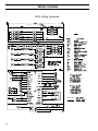
READ AND SAVE THESE INSTRUCTIONS
This manual must be left with the owner and should be accessible for reference.
DRI-STEEM Models
GTS and GTS-DI
®
®
GAS-TO-STEAM HUMIDIFIERS
User's/Installation Instructions
and
Maintenance Operations Manual
WARNING: If the information in this manual
is not followed exactly, a fire or explosion
may result causing property damage,
personal injury, or loss of life.
• Do not store or use gasoline or other flammable vapors and
liquids in the vicinity of this or any other appliance.
WHAT TO DO IF YOU SMELL GAS
• Do not try to light any appliance.
• Do not touch any electrical switch; do not use any
phone in your building.
• Immediately call your gas supplier from an off-site
phone. Follow the gas supplier's instructions.
• If you cannot reach your gas supplier, call the fire
department.
• Installation and service must be performed by a qualified
installer, service agency, or the gas supplier.
For Toll-Free Technical
Support, Call: 1-800-328-4447
TABLE OF CONTENTS
TO THE PURCHASER AND THE INSTALLER
Thank you for purchasing DRI-STEEM Model GTS® equipment. We have designed and built this equipment to give you
total satisfaction and many years of trouble-free service. Proper installation and operating practices will assure you of
achieving that objective. We therefore urge you to become familiar with the contents of this manual.
DRI-STEEM Humidifier Company
GTS Program Code Nomenclature ...................................... 3
Models GTS and GTS-DI Humidifiers .................................. 4
Safety Precautions ................................................................ 5
Installation
Precautions ................................................................ 6
Required Clearance ..................................................... 6
Locating the Humidifier .............................................. 7
Supply Water and Drain Overflow Connections ........ 7
Drain Piping and Material ........................................... 8
Make-up Water Piping and Material .......................... 8
Vapor Hose Piping ..................................................... 8
Gas Piping ................................................................. 9
Gas Leak Testing ....................................................... 9
Electrical .................................................................... 10
Combustion and Ventilation Air .................................. 10
Venting Guidelines (Stack Connection) ..................... 11
Specifications and Capacities ............................................. 13
Dimensions ........................................................................... 14
Piping Diagrams: Gas, Water, and Drain ........................... 15
Mounting the Humidifier ..................................................... 16
Steam Supply Connection Methods ................................... 17
Dispersion Tube Installation ............................................... 18
RAPID-SORB® Assembly and Installation
Horizontal Duct Installation .....................................19
Vertical Duct Installation .........................................20
ULTRA-SORB® Installation .................................................. 20
AREA-TYPE Application ...................................................... 21
Start-up and Operation ........................................................ 22
Maintenance
GTS (Standard Model Only) ...................................... 23
GTS-DI Model Only ................................................... 23
Both GTS and GTS-DI ............................................... 24
Air Shutter Adjustment Procedure ............................. 25
Replacement Parts ............................................................... 26
Wiring Diagrams .................................................................. 28
Caution Labels ..................................................................... 32
Gas Control Valve ................................................................ 33
Maintenance Service Record .............................................. 34
Two-Year Limited Warranty ................................................ 36
2
GTS PROGRAM CODE NOMENCLATURE
GTS PROGRAM CODE NOMENCLATURE
1
T
O
O
X
7
8
A
(Example)
How many tanks are in the system
(1-6)
What type of control does the unit have
S - Single staged
E - Externally staged
Z - Zone valve
T - TP
X – Slave
M – Master
Does the unit have VAV
V - Yes
O - No
Does the unit have temperature compensation
T - Yes
O - No
Humidity sensor type
C - 0-135 OHM humidistat Electric
D - 6-9 VDC humidistat
F - 1-10 VDC humidistat
E - 4-20 mA humidistat
X - 4-20 mA transmitter
S - Slave
N - None (On/Off)
P – 0-135 OHM humidstat Pneumatic
Burner size
5-50 MBH
7-75 MBH
1-100 MBH
6-67.5 MBH
Burner quantity
1 - One staged
2 - Two staged
4 - Four staged
5 - One modulating
6 - Two modulating
8 - Four modulating
Water level control
D - DI with manual drain
E - DI with auto drain (end of season)
M - Probe with manual drain
A - Probe with auto drain
3
GTS® AND GTS-DI HUMIDIFIERS
GTS Gas-to-Steam
Humidifier
This humidifier is designed to be
used with either softened or
unsoftened water. (Softening is
recommended to reduce need for
cleaning.) The probe-type level
control system requires water
conductivity of 100 micromhos/cm,
this translates to about 2 grains/gal
minimum to function, and therefore
will not operate on water treated by
reverse osmosis or deionization.
However, GTS humidifiers are
available for use with these water
types. The standard humidifier can
be converted in the field to a demineralized model. See below.
ULTRA-SORB ®
Control Panel
Cover
Knob
Low-Water
Switch
Blower
Cover
Evaporating
Chamber
Heat Exchanger
Shroud
Fill Valve
Probes
Flue Box
Manual or
Electric Drain Valve
Blocked Vent Tap
Gas Valve
OM-730
GTS-DI Option
For use with deionized or reverse
osmosis water. This unit produces
chemical-free steam and reliable,
accurate humidification control. It
is virtually maintenance-free, with
no wasted water, heat, or downtime.
The DI unit uses a float valve to
control water levels.
RAPID-SORB ®
Low-Water
Cover
Control Panel Knob Switch
Blower
Cover
Evaporating
Chamber
Heat Exchanger
Shroud
Float Valve
Low-Water Cut-Out
Flue Box
Blocked Vent Tap
Drain Valve
Gas Valve
OM-735
4
SAFETY PRECAUTIONS
WARNING:
Improper installation, adjustment, alteration, service,
maintenance, or use can cause carbon monoxide
poisoning, an explosion, fire, electrical shock, or other
conditions which may cause personal injury or property
damage. Consult a qualified installer, service agency,
local gas supplier, or your distributor or branch for
information or assistance. The qualified installer or
agency must use only factory authorized and listed kits
or accessories when modifying this product. A failure
to follow this warning can cause electrical shock, fire,
personal injury, or death.
• Inspect humidifier and accessories upon arrival for
damaged, missing, or improper parts. If there is a
problem, call DRI-STEEM.
• Application of this humidifier should have special
attention given to vent sizing and material, gas input
rate, and unit sizing. Improper installation or misapplication of the humidifier can require excessive servicing
or cause permanent component failure.
• When working on equipment, observe precautions in
this literature, tags, and labels attached to or shipped
with the unit and other safety precautions that may
apply. Wear safety glasses and work gloves. Have fire
extinguisher available during start-up, adjustment
procedures, and service calls.
• Do not use this appliance if any part has been under
water. Immediately call a qualified service technician to
inspect the appliance and to replace any part of the
control system and any gas control which has been
under water.
• Do not lift humidifier by gas controls, gas manifold,
fire box, or control shroud.
• Should overheating occur, or the gas supply fail to
shut off, shut off the manual gas valve to the appliance
before shutting off the electrical supply.
5
INSTALLATION
Precautions
Required Clearance:
• The installation must conform to the requirements of
the authority having jurisdiction or, in the absence of
such requirements, to the National Fuel Gas Code,
ANSI Z223.1 (latest edition). In Canada, the installation
of this unit must comply with local plumbing or waste
water codes and other applicable codes and with the
current code CAN/CGS-B149.1 "Installation Code for
Natural Gas Burning Appliances and Equipment" or
CAN/CGA-B149.2, "Installation Code for Propane
Burning Applications and Equipment."
For recommended service and maintenance purposes the
following clearances should be maintained:
•
•
•
•
•
Heat exchanger removal - front, 30"
Burner shroud removal - front, 24"
Control cabinet - left side, 36"
Drain valve - right side, 12"
Clean-out tray - rear, 30"
(not applicable with DI/RO systems)
• Cover removal - top, 18"
• Distance from vent box to combustible
floor - 30"
• Do not install in potentially explosive or flammable
atmospheres laden with grain dust, sawdust, or similar
airborne materials.
GTS clearance recommendations
• Installation of humidifier in high humidity or salt water
atmospheres will cause accelerated corrosion, resulting
in a reduction of the normal life-span of the unit.
Control cabinet, 36"
Cover, 18"
• To prevent premature heat exchanger failure, do not
locate ANY gas-fired unit in areas where chlorinated,
halogenated or acid vapors are present in the atmosphere.
0"
t
ou
3
y,
tra
n
ea
Cl
• Locate the humidifier in an area clear of combustible
materials, gasoline, and other flammable vapors and
liquids.
Drain valve, 12"
• Do not locate units in tightly sealed rooms or small
compartments without provision for adequate combustion
air and venting. Combustion air must be supplied to the
room through a minimum of two permanent openings in
the wall, at least one near the bottom. The openings
should provide one square inch of free area per 1000
BTUH input rating of the unit with a minimum of 100
square inches for each opening, whichever is greater.
See table 10-1 and information on pages 10 and 11 for
additional details.
6
Burner
shroud,
24"
30"
Heat exchanger, 30"
Floor
INSTALLATION
Important:
• Remove all shipping brackets and materials before
operating the humidifier.
• Humidifier flue gases must be vented to the outside
atmosphere.
• Power supply disconnect switch must be in the off
position while making wiring connections to prevent
electrical shock and equipment damage. All units must
be wired in strict accordance with wiring diagram furnished
with this unit.
• Turn off all gas while installing the run-out and manual
shut-off valve for the humidifier.
Locating the Humidifier
• Provide a level, solid foundation for the humidifier.
Locate the humidifier as near as possible to chimney or
outside wall so that the flue pipe from the humidifier is
short and direct. The location should also be such that
the gas ignition system components are protected from
water during humidifier operation and service.
• The humidifier should be installed in a location away
from drafts and properly protected. If installed in a
separate room, follow the instructions concerning
combustion and ventilation air.
• The humidifier should be located in an area where
leakage from the tank or its connections will not result
in damage to the adjacent structure or to lower floors of
the structure. When such locations cannot be avoided,
it is recommended that a suitable drain pan, adequately
drained, be installed under the humidifier. The pan must
not restrict combustion air flow.
• The humidifier must not be installed on carpeting, tile,
or other combustible material other than wood flooring
(indoor application only).
• Install humidifier so electrical components are protected from water.
Supply Water and Drain Overflow
Connections
IMPORTANT: The humidifier is shipped with the automatic drain valve locked in the manual open position.
This position reduces the possibility of damaging the
valve seat from the heat of sweating the drain connection
during installation. After the drain connection has been
completed the "manual open" lever position must be reset
to the auto position. Failure to close the drain valve will
not allow the tank to fill.
Regardless of the type of water used, the following
general instructions must be followed:
• Union connections must be made at the humidifier on
the cold water supply and drain/overflow lines.
• A shut-off valve should be provided in the supply water
line to isolate the humidifier from the water system while
servicing.
• If the water pressure is above 60 psi and/or water
hammer would be objectionable, a pressure reducing
valve or shock arrester should be installed.
• A 3/4” opening is provided in the humidifier tank to
accommodate skim and/or overflow protection. A water
seal is required on the drain/overflow connection and a 1”
air gap should be provided prior to a building drain. (Note:
Follow local code requirements regarding size of drain
pipe.) The water seal must be piped to hold steam in the
humidifier and also provide a pressure relief if the steam
outlet becomes clogged. (See diagram on page 15)
• Insulating unions or bushings must be used to make
connections between copper and other dissimilar metal
fittings, such as galvanized steel. These insulating
fittings are required to minimize electrolytic corrosion,
which results from the direct connection of dissimilar
metals in a water system.
• Before beginning ignition sequence of the humidifier at a
new installation, be sure the humidifier tank is full of water
and the water is free to flow into the tank.
• The appliance must be kept free and clear of insulating materials when located in an insulated space.
Insulating material may be combustible. Inspection of
the appliance area must be performed when the appliance is installed, or when insulation is added.
7
INSTALLATION
Drain Piping and Material
Drain piping diagrams are provided on page 15. If nonmetallic pipe or hose is used, it must be capable of
withstanding temperatures up to 212°F.
To prevent steam from escaping out the drain line, a
water seal must be provided in the drain line of sufficient
height to contain the pressure developed within the
humidifier and steam dispersion system. To determine
the proper height of the water seal, see table 15-1 on
page 15.
As part of the fill valve assembly, the needle valve
restricts the rush of cold water entering the evaporating
chamber during the fill cycle. Adjusting the supply water
flow with the needle valve will reduce fill cycle noise
from the collapsing steam head in the humidifier. Adjusting the needle valve will also reduce the drop in
output during a fill cycle. Care must be taken to not
reduce the fill rate below the humidifier's capacity, this it
will cause a low-water shutdown.
Vapor Hose Piping
Make-up Water Piping and Material
Make-up water piping diagrams are provided on page 15.
Minimum make-up water pressure must be 25 psig.
When non-metallic water piping is used, it must be rated
to withstand 212°F or greater temperature. If not, the
final 3 feet connected to the humidifier should be metallic
and should not be insulated.
When a vapor hose and stainless steel dispersion
tubes are used, they should be pitched back to the
humidifier. A minimum slope of 2" per foot (with no “low
spots”) is recommended. When this is not possible due
to duct elevation or an obstruction, alternate arrangements may be used as shown in figures 8-1 and 8-2
below.
Any condensate that forms in the vapor hose must be
removed. Preferably, it should be returned to an open
drain with a water seal of sufficient height to contain the
duct static pressure, as shown in figure 8-1.
Figure 8-1: Piping method recommended when
obstruction prevents dispersion tube from being
continuously pitched back to humidifier
Figure 8-2: Piping method recommended when
humidifier must be mounted higher than the duct
Inline Tee
(1½" Dia. - Part # 162710)
(2" Dia. - Part # 162712)
Obstruction
Duct
Duct
GTS
GTS
4" Min. 5" Min.
¾" Tubing
Funnel or
Floor Drain*
OM-749
Notes:
• The GTS typically requires multiple dispersion tubes.
* Refer to local codes for drain pipe size requirements.
8
Inline Tee
(1½" Dia. - Part # 162710)
(2" Dia. - Part # 162712)
OM-750
INSTALLATION
Gas Piping
(See "Gas Piping" diagram on page 15.)
• Do not use soap solution, or open flame on humidifier
gas train. A gas leak detector is recommended.
CAUTION:
Gas pressure to humidifier controls must never
exceed 14” W.C. (1/2 psi). A 1/8" inch NPT plugged
tapping, accessible for test gauge connection, must
be installed immediately upstream of the gas supply
connection to the appliance.
• Install a ground joint union and a manual shut-off valve
immediately upstream of the unit including a 1/8” NPT
plugged tapping accessible for test gauge connection.
Plugged tappings for test gauges are located on all gas
valves.
• Allow at least 5 feet of piping between any high
pressure regulator and unit pipe connection.
• Piping installation must be in accordance with local
codes, and ANSI Z233.1, “National Fuel Gas Code,” or
CAN/CGA-B149 in Canada. Do not use flexible connectors.
Gas Leak Testing
• When leak testing the gas supply piping system, the
humidifier and its gas shut-off valve must be disconnected
during any pressure testing in excess of 14” W.C. (½ psi).
The humidifier must be isolated from the gas supply piping
system by closing its field-installed manual shut-off valve
during any pressure testing equal to or greater than 14"
W.C. (½ psi).
• Piping to units should conform with local and national
requirements for type and volume and gas handled, and
pressure drop allowed in the line. Refer to table 9-1 and
9-2 to determine the cubic feet per hour (cfh) for the
type of gas and size of unit to be installed. Using this
value and the length of pipe necessary, determine the
pipe diameter. Where several units are served by the
same main, the total capacity, gas flow (cfh), and length
of main must be considered. Avoid pipe sizes smaller
than 1/2”. Table 9-1 allows for the usual number of
fittings with a 0.3” W.C. pressure drop.
• Check gas supply pressure with all burners running at
inlet pressure tap of combination gas control. (See page
33) The recommended supply pressure should be 7"
W.C. on natural gas or 11" W.C. on LP gas. Purging of
gas piping should be performed as described in ANSI
Z223.1 (latest edition) or, in Canada, in CAN/CGA-B149
codes.
• After threading and reaming the ends, inspect piping
and remove loose dirt and chips.
• Minimum supply pressure. Natural - 4½" W.C.
LP - 10" W.C.
• Support piping so that no strains are imposed on unit
or controls.
• Single stage gas valves GTS™-300, 150, and 75 outlet
pressure (manifold) should be factory set at 3 1/2" w.c. for
natural, 9" w.c. for L.P. This pressure can be checked on
the combination gas valve at the out pressure tap (see
page 33).
• Use two wrenches when connecting piping to unit
controls.
• Provide a drip pocket before each unit and in the line
where low spots cannot be avoided.
Table 9-1: Gas Pipe Capacities for Gas
• Take-off to unit should come from top or Pressures of .5 PSIG or Less
side of main to avoid trapping condenGas Flow in Piping (Cu. Ft. per Hr.)
sate.
• Piping subject to wide temperature
variations should be insulated.
• Pitch piping up toward unit at least
1/4” per 15’ of horizontal run.
• Compounds used on threaded joints of
gas piping must be resistant to the
harmful action of liquefied petroleum
gases.
• Purge air before lighting unit by
disconnecting piping at gas control. In
no case should line be purged into
heat exchanger.
• After installation, check field piping
and humidifier gas train for gas leaks.
Length
of Pipe
Feet
(At pressure drop of 0.3 in. water.
Specific gravity = 0.60)
Iron Pipe Size (NPT) Inches
1/2
3/4
1
1-1/4
1-1/2
10
132
278
520
1050
1600
20
92
190
350
730
1100
30
73
152
285
590
890
40
63
130
245
500
760
50
56
115
215
440
670
60
50
105
195
400
610
Table 9-2: Specific
Gravity Conversion
Factors
Multiplying factor to be used
with table 9-1 when the
specific gravity of gas is other
than 0.60.
Natural Gas
Specific
Gravity
Factor
0.55
1.04
0.60
1.00
0.65
0.962
Propane Gas
70
46
96
180
370
560
Specific
Gravity
80
43
90
170
350
530
1.50
90
40
84
160
320
490
1.53
0.626
460
1.60
0.612
100
38
79
150
305
Factor
0.633
9
INSTALLATION
• Two stage gas valves (used on GTS® 400, 200 and 100)
have a 10 second high fire stage and then drop to a
normal fire stage. Factory settings for natural gas are 5"
w.c. high, 3 1/2" w.c. normal. Factory settings for L.P. gas
are 8" w.c. high, 6" w.c. low. These pressures can be
checked on the combination gas valve at the out pressure
tap (see page 33).
Electrical
CAUTION:
Do not connect aluminum wire between disconnect
switch and humidifier. Use only copper wire.
WARNING:
The cabinet must have an uninterrupted or unbroken
ground according to National Electrical Code, ANSI/NFPA
70 and Canadian Electrical Code, CSA C22.1, or local
codes to minimize personal injury if an electrical fault
should occur. This may consist of electrical wire or
conduit approved for electrical ground when installed in
accordance with existing electrical codes. Do not use gas
piping as an electrical ground.
• GTS Humidifiers should be supplied with 120-volt AC,
60-Hz, 15-amp separately fused electrical service. The
GTS humidifier is equipped with a transformer to step
down the voltage to 24 VAC control voltage.
• When installed, the GTS humidifier must be electrically
grounded in accordance with local codes or, in the absence of local codes, with the National Electrical Code
ANSI/NFPA No. 70-1987. The electrical conductors shall
be Type MTW (105°C) AWG #14 wire for line voltage
(120V), with BLACK WIRE for HOT; WHITE WIRE for
NEUTRAL, GREEN WIRE for GROUND; and #18 gauge
for control wiring. All electrical components and wiring
must be protected from mechanical damage and water.
The control system requires an earth ground for proper
operation.
• The humidifier is adjusted for correct performance. Do
not alter fan or operate motors at reduced speed.
• The current characteristics, and capacity requirements
should be checked against the nameplates. All wiring
must be in accordance with all governing codes, and with
GTS wiring diagram located inside the control cabinet.
See table 13-1 for information on the various models.
• See page 14 for recommended knockout locations for
the electrical power supply and control wiring connections
on the control cabinet.
• See separate publication for the specific controller
furnished with this specific GTS humidifier.
Combustion and Ventilation Air
CAUTION:
Air for combustion must not be contaminated by
halogen compounds, which include fluoride, chloride,
bromide and iodide. These elements are found in
aerosol sprays, detergents, bleaches, cleaning solvents, salts, air fresheners, and other household
products.
CAUTION:
The operation of exhaust fans, kitchen ventilation
fans, clothes dryers, or fireplaces could create a
negative pressure condition at the humidifier. Makeup air must be provided for the ventilation devices, in
addition to that required by the humidifier.
• All fuel burning equipment must be supplied with air for
combustion of the fuel. Sufficient air MUST be provided
to ensure there will not be a negative pressure in the
equipment room or space.
• Provisions for adequate combustion and ventilation air
must be provided in accordance with Section 5.3, Air for
Combustion and Ventilation, of the National Fuel Gas
Code, ANSI Z223.1-1988, or applicable provisions of the
local building codes. Canadian installations must be
installed in accordance with sections 7.2, 7.3, and 7.4 of
the CAN/CGA.B149 Installation Codes, and all authorities
having jurisdiction.
Table 10-1: Location of Humidifier and Required Air
Openings to Confined Space
Confined Space - All air
from inside the building;
conventional frame.
Brick or stone
construction with normal
infiltration. (Can only be
rarely used with larger
input units.)
Two openings, 1 square
inch per opening per
1000 BTU/hr. input.*
Confined Space - All air
from outside the building
through air ducts.
Two openings, 2 ducts, 1
square inch per opening
per 2000 BTU/hr. input.*
Confined Space - All air
from outside the
building, through wall
openings only (no
ducts.)
Two openings, 1 square
inch per opening per
4000 BTU/hr. input.*
Unconfined Space - All
air from outside the
building.
Same as confined
space, all air from
outside the building.*
The minimum free area
of opening is 100 square
inches.
*Note the minimum dimension of any opening is three
inches.
10
INSTALLATION
• For proper and safe operation this appliance needs air
for combustion and ventilation. DO NOT block or
obstruct air openings on the appliance, spaces around the
appliance, or air openings communicating with the appliance area.
• DO NOT block the flow of combustion and ventilation
air. To provide for necessary oxygen for proper combustion, opening must be provided to allow outside air to enter
the space in which the heater is located. Enclosed
spaces, such as equipment rooms, must be vented at the
blower for combustion air. The size of air openings must
be based on all gas-burning equipment installed in the
space involved. Four types of locations, and the requirements of each, are outlined in table 10-1, on page 10.
Vertical and Horizontal Venting Guidelines
(Stack Connection)
• The GTS® is a fan assisted category 1 appliance.
• The purpose of venting the gas humidifier is to completely remove all products of combustion and ventilation
gases to the outside air, without condensation in the
stack.
• When connecting the humidifier to a gas vent or chimney, the installation shall be in accordance with Part 7,
Venting of Equipment, of the National Fuel Gas Code,
ANSI Z223.1, or Section 7, Venting Systems and Air
Supply Appliances, of the CAN/CGA B149 Installation
Codes, the local building codes, and the vent
manufacturer's instructions.
• Do not reduce the vent diameter, and avoid short turns
in the vent piping. Use the same size stack as the vent
furnished with the humidifier. Maintain a minimum
upward slope of 1/4-inch-per-linear foot on all horizontal
runs. Maintain proper support of vent connections and
joints. Observe clearances (in accordance with applicable codes) from all combustible materials, and obtain
an approved cap for the stack outlet. The bottom of the
cap must be one stack diameter above the top of the
stack.
• Inspect for proper and tight construction. Any restrictions or obstructions must be removed. An existing
chimney may require cleaning.
• Chimney or vent must extend at least 3 feet above its
passage through a roof and at least 2 feet above any ridge
within 10 feet of the chimney. (Local codes apply.)
• Minimum clearance from the vent connector to combustible material is 6 inches unless the combustible materials
are protected in accordance with applicable codes. The
recommended vent system for the GTS-400, 200 and
100 humidifiers is constructed of Type C single wall vent
pipe (UL or CUL listed). Type C vent requires varying
levels of insulation when penetrating a combustible wall
depending on vent temperatures.
• This humidifier must not be connected to a chimney flue
servicing a separate appliance designed to burn solid
fuel.
• Never connect this humidifier to a chimney serving a
fireplace, unless the fireplace opening is permanently
sealed off.
• The recommended vent system for the GTS-300, 150,
and 75 humidifier is constructed of Type B double-wall
vent pipe (UL or CUL listed). Type B vent is rated for
400°F plus ambient temperature. A minimum 1-inch
clearance is required between Type B vent and combustible materials. Field expertise has shown that venting
through a properly sized Type B vent significantly
reduces the occurrence of vent condensation.
• It may be necessary to add insulation to Type B doublewall vent and to single-wall vent connector, if allowed by
local codes, in some applications. When insulation is
required, it must be at least 1-inch thick fiberglass with foil
backing. Using permanent foil tape, attach insulation to
vent pipe. Both the foil tape and fiberglass insulation
must be suitable for temperatures up to 450°F.
• Insulation must be added to any vent connector which
will be exposed to ambient temperatures of 30°F or less,
especially any application using single-wall vent pipe as a
connector.
• Do not insulate vent pipe exposed to outdoor weather
conditions (i.e. above roof lines).
• Venting into an unlined masonry or concrete chimney is
prohibited by code.
• If this humidifier is connected to a lined, masonry
chimney, the chimney must be sized and installed according to the provisions of the National Fuel Gas Code, or
Canadian CAN/CGA.B149 requirements. Vent connectors
from the humidifier to the chimney should be made with
insulated Type C single-wall vent pipe or Type B vent
pipe for GTS-300, 150, and 75. The GTS-400, 200 and
100 is approved for single wall vent only.
• Installation of the vent pipe should be as directly as
possible, with a minimum number of turns or elbows.
• Rigidly support the vent pipe every 5 feet or less with
hangers or straps to ensure that there will be no movement after installation. The humidifier vent box should not
be supporting the weight of the vent piping.
11
INSTALLATION
• No portion of the vent system shall extend into, or pass
through, any circulation air duct or plenum.
• The Type B vent system shall terminate above the roof
surface per the National Fuel Gas Code or CAN/
CGA.B149 requirements, and shall include a UL or CUL
listed vent cap or roof assembly, unless prohibited by
local codes.
• This humidifier may be commonly vented with other
listed gas-fired appliances. Total input rates of all appliances will determine the vent size.
• All vent pipe passing through floors, ceilings, and walls
must be installed with the proper clearances from combustible material, and be fire-stopped according to the
National Fuel Gas Code requirements and Canadian
Standards CAN/CGA.B149.
• 60' maximum, 10' minimum equivalent length of vent pipe.
• A vent box pressure of -.01" w.c. is specified and set by
adjusting power venter and barometric damper, with all
burners running.
• Maximum of 4 elbows
GTS™ Model
Equivalent Length
of Vent Pipe/Elbow
Vent Terminal
Model Number
Power
Venter
Barometric
Damper
GTS - 400
7'
SWH-1-5 (5")
5" PVO-600
5"
GTS - 300
7'
SWH-1-5 (5")
5" PVO-600
5"
GTS - 75, 100, 150, 200
6'
SWH-1-4 (4")
4" PVO-300
5"
• Vent pipe is single wall or B vent for GTS-300, 150, 75.
• Vent pipe is single wall only on GTS-400, 200, and 100.
Equipment Required for Horizontal Venting
• In replacement installation, where an existing vent
system may be used, the vent system must be inspected
for condition, size, type of vent material, and height to
meet the requirements in these instructions. If the
existing vent system is too large, condensation could
occur, causing corrosion of the vent system. Installing a
replacement vent system may be required. When connecting the humidifier to a gas vent or chimney, the
installations shall be in accordance with Part 7, Venting of
Equipment, of the National Fuel Gas Code, ANSI Z223.1,
or Section 7, Venting Systems and Air Supply Appliances,
of the CAN/CGA B149 Installation Codes, the local
building codes, and the vent manufacturer's instructions.
• For all applications, the horizontal length of the vent and
vent connector must not exceed the height of the vent
system.
• Power Venter: Field controls, see above table for
model numbers.
• Barometric Damper: Field controls model # MG-1 (5").
• Vent Terminal: Field controls, see above table for
model numbers.
Figure 12-1: GTS Venting
Barometric
Draft Control
Vent
Hood
Power Venter
Special Horizontal Venting Requirements
• Distances from the vent terminal adjacent public
walkways, buildings, and openable windows and building
openings should be consistent with the National Fuel Gas
Code, ANSI Z223.1, and/or CAN/CGA B149 Installation
Codes.
• The vent terminal and air intake locations must be at
sufficient height above ground level to prevent blocking by
expected snowfall.
• Building materials should be protected from degradation by flue gases.
• A minimum horizontal clearance of 4 feet (1.22m) from
electric meters, gas meters, regulators, and relief
equipment must be maintained.
12
X
GTS Humidifier
Recommended Value for
X Approximately 12"
3½ Feet Minimum
X
Air Intake
Note: Refer to power venter manual for clearance requirements relative to
combustion air openings.
SPECIFICATIONS AND CAPACITIES
Table 13-1: Specifications
115 volt, 60 Hz
Steam
capacity
per hour
in lbs.
(kg.)
*MBH
input
GTS-75
55
(25)
75
1
5
(130)
400
(180)
GTS-100
75
(34)
100
1
5
(130)
GTS-150
110
(50)
150
2
GTS-200
150
(68)
200
GTS-300
225
(102)
GTS-400
300
(136)
Model
number
Heating
stages
Vent size
in inches
(mm)
Operating
weight
in lbs.
(kg.)
Shipping
weight
in lbs.
(kg.)
Full
load
amps
Max.
fuse
size
230
(105)
2.5
400
(180)
230
(105)
5
(130)
525
(240)
2
5
(130)
300
4
400
4
Performance derate impact
Vertical vent
Horizontal vent
Natural
gas
LP
gas
Natural
gas
LP
gas
15
0%
10%
10%
10%
2.5
15
0%
4%
0%
4%
300
(135)
3.5
15
0%
10%
10%
10%
525
(240)
300
(135)
3.5
15
0%
4%
0%
4%
7
(180)
775
(350)
400
(180)
5.0
15
0%
10%
10%
10%
7
(180)
800
(365)
425
(195)
5.0
15
0%
4%
0%
4%
* Altitude adjustment note for Canada:
Altitude in feet
Percent of listed input
0-2000
100%
2000-4500
90%
* Altitude adjustment note for United States:
100% up to 2000'
4% derate/1000' over 2000'
Capacity Notes
• Approximately 172 BTU’s are required to raise the
temperature of one pound of water from 40° to 212° F.
• The ¾" rigid foil faced fiberglass insulation on all
surfaces of evaporating chamber increases unit efficiency
by approximately 2%.
• Another factor to consider is condensation steam loss
from hoses and tubes. Use the following steam loss
guidelines:
- vapor hose: 0.15 lbs/ft/hr
- insulated pipe: 0.05 lbs/ft/hr
- dispersion tubes: 0.50 lbs/ft/hr
• An additional 970 BTU’s are required to change one
pound of water to water vapor.
13
DIMENSIONS
Recommended
ZTU cord location
knockout
Figure 14-1: Dimensions
E
D
K
B
H
Recommended
power supply
knockout
J
C
F
G
L
Recommended
low voltage
control wiring
knockout
¾” Copper
drain
N
A
Side View
Front View
Side View
Clean-out tray
¼” NPT Fill
Table 14-1: Dimensions
Description
M
Top View
14
GTS®-75
GTS-100
(One burner)
GTS-150
GTS-200
(Two burner)
GTS-300
GTS-400
(Four burner)
19"
19"
27½"
A
Floor stand width
B
Overall length
54¼"
54¼"
54¼"
C
Height of evaporating chamber
17¾"
23½"
25¼"
D
Distance from steam outlet to side of unit
9¼"
9¼"
13½"
E
Overall width
27"
27"
37½"
F
Height of control cabinet
20"
20"
24"
G
Shroud height
20"
25¾"
27½"
H
Distance from top of shroud to gas inlet
11¾"
11"
14"
J
Gas inlet
½" NPT
¾" NPT
1" NPT
K
Distance from flue to side of unit
6¼"
6¼"
6½"
L
Distance from flue to front of tank
3¾"
3¾"
4¾"
M
Flue diameter
5"
5"
7"
N
Distance from floor to bottom of tank
28½"
22¾"
21"
PIPING DIAGRAMS: GAS, WATER, AND DRAIN
Steam Outlet
Standard Unit (Non-DI/RO Water)
Needle Valve
Water Supply Line (25 psi minimum)
Solenoid Water Make-up Valve
Three-Probe Level Control
and Low Water Cut-off
Water Skim/Overflow Outlet
Manual Electric Drain Valve
Shroud
Drain and Water Seal Piping* (by installer)
*
Air Gap
**
Open Drain**
OM-736
Flue Connection
Gas Piping
Drain piping material must be suitable for
212°F (100°C) water.
Refer to local codes for drain pipe sizing and
maximum temperature requirements.
GTS®-DI
Steam Outlet
¼" NPT Water Supply
(30 psi minimum)
Gas Supply Line
Plugged 1/8" NPT
Test Gage
Connection*** Ground Joint
Gas Cock***
Union with
Brass
Seat***
Float-Operated Water
Make-up Valve
To Humidifier Gas
Connection (elbow
supplied by DRI-STEEM)
Float-Operated
Low-Water Cut-off
¾" SST Drain Valve
Drain and Water Seal
Piping* (by installer)
3" Min.
Air Gap
Humidifier Shroud
Drip Pocket***
***
OM-764
OM-737
* Drain piping material must be suitable for 212°F (100°C) water.
** Refer to local codes for drain pipe sizing and maximum temperature
Supplied by others.
Alternate Water Seal and Drain Valve Piping (by installer)
Used when water seal must be elevated above flow line of drain
connection (humidifier near floor)
Needle Valve
Water Supply Line
(25 psi minimum)
Water Skim/Overflow Outlet*
requirements.
Table 15-1: Water Seal Height
Recommendations
Humidifier
Solenoid Water
Make-up Valve
Lbs/Hr
Height
(Inches)
*Overflow Pipe
(Inches)
GTS-75
55
12
¾
GTS-100
75
12
¾
GTS-150
110
12
¾
GTS-200
150
12
¾
GTS-300
225
18
1
GTS-400
300
18
1
Manual or Optional
Electric Drain Valve
Note: Flow Line of Water
Seal cannot be above
Flow Line of Skimmer
Outlet
Note: If piping to dispersion tube is over 20 feet increase water seal height by 15%.
Air Gap
OM-738
Open Drain **
Overflow
Open Drain**
* Piping material
** Refer to local
must be suitable for 212°F (100°C) water.
codes for drain pipe sizing and maximum temperature
requirements.
15
MOUNTING THE HUMIDIFIER
For proper operation of the electrode-probe, water-level
control and the skimmer system, the humidifier must be
mounted level left to right and front to rear.
forms on the heat exchanger continuously flakes off as it
forms and settles to the bottom. A clean-out tray on the
floor of the tank may be removed periodically through the
back clean-out opening.
Proper access (18" minimum) for periodic removal of the
top cover is recommended. In most cases, scale that
Figure 16-1: Mounting Support Methods
Angle iron supported on roof
trusses or other overhead
structure capable of holding
weight (field provided)
Trapeze
(GTS 75 & 100 only)
3/8" Threaded Rod
Vent
Double Nut
Rear Tank
Flange
Note:
The trapeze bars will span the width of the tank and should be resting against the
front and rear tank flanges. Holes should be drilled in overhead support to provide
vertical installation of threaded rod. Double nuts are recommended below the
trapeze bars and above the overhead support. Unit must be installed level in all
directions and clearances must be provided according to the nameplate (rating plate)
on the humidifier.
Floor Stand
Angle Iron
Trapeze Bars
Front Tank Flange
OM-763
Vent
3 Mounting
Holes Requiring
1/4" x 20 Bolts
Support Legs
16
STEAM SUPPLY CONNECTION METHODS
Figure 17-1: Steam Supply Using Vapor Hose
Vapor hose. See table 18-2 for sizing. (Pitch back min. 2" per foot to humidifier with supports
to prevent sagging.) Maximum length 10'. Humidifier must be mounted level.
Stainless steel dispersion tube in middle of duct. Pitch as shown
in figure 18-1. Typically, GTS® requires multiple
dispersion tubes. See table 18-2 on page 18 for
capacities.
OM-733
Figure 17-2: Steam Supply Using Pipe or Tubing
(Flange option available)
Pipe Insulation Recommended
OM-743
17
DISPERSION TUBE INSTALLATION
Dispersion Tube Installation with Condensate Drain
(over 28 pph per dispersion tube)
Figure 18-1: Single Tube
Vapor Hose
• Vapor hose should be supported to
prevent sags or low spots and to
maintain a minimum pitch of 2" per
"B" Dia. (TYP)
foot back to the humidifier.
.25" Dia. (TYP)
• For mounting the humidifier above
the level of dispersion tube, see figure
.625 Dia.
8-2 on page 8.
Failure to follow the above recommendation may result in excessive back
pressures being imposed on the humidifier. This in turn may lead to dispersion
tube(s) spitting, lost water seals or
leaking gaskets. When the distance
between humidifier and the dispersion
tube(s) exceeds 10 feet, consult factory
for special recommendations.
Rigid Piping
• Vapor piping should have a minimum
I.D. equal to the cover outlet of the
humidifier.
• A minimum pitch of 2" per foot back to
the humidifier should be maintained.
• 90° elbows are not recommended, use
two 45° elbows one foot apart instead.
• Thin-wall tubing will heat up faster and
cause less start-up loss than heavywall pipe.
• Insulating the rigid piping will
reduce the loss in output caused by
condensation.
Pre-molded High
Temperature Resin
Steam Tubelets
A
A
¼"/ft Pitch
Support
Bracket
3.25"
½" O.D.Copper
(condensate drain)
3.25"
¼" NPT Coupling
Movable Duct Plate (Can be mounted within limits of 2.5".)
OM-351
Table 18-1: Dispersion Tube Capacities
Tube
Diameter
Capacity
1½"
2"
A
B
57 lbs/hr
3.25"
1.51"
85 lbs/hr
5.00"
2.03"
With
Drain
Figure 18-2: Multiple
Tube with Condensate
Wasted to Floor Drain
Dispersion Tube
Duct
Dispersion Tube
1-½" Dia. Vapor Hose or
Hard Tubing
6"Min.
GTS® Humidifier
Water Seal
(5" approx.)
½" O.D. Condensate Drain Tube
Condensate Drain
Tube (by others (3/4" minimum))
Floor Drain*
Tube Mounting
• Mount dispersion tubes pitched
as stated above.
• Tubelets must discharge perpendicular to air flow.
* Return line piping material must be
suitable for 212°F (100°C) water.
OM-747
Piping/Hose Sizing from the GTS® to a RAPID-SORB® panel
Table 18-2: Maximum Steam Carrying Capacity*
Copper or Stainless
Steel Tubing or
Schedule 40 Steel Pipe
Vapor Hose
Min. Condensate Drain Line Sizes
• One or two tubes: 3/4" I.D.
• Three or more tubes: 1" I.D.
18
*Refer to local
codes for drain pipe
sizing requirements.
20 Feet (**)
10 Feet (**)
Hose
I.D.
Developed
Length
in Feet(**)
Tubing
O.D.
Developed
Length
in Feet(**)
lbs/hr
kg/hr
1 ½"
150
68
1 ½"
lbs/hr
140
kg/hr
64
2"
250
113
2"
210
95
--
--
--
3"
410
186
318
--
--
--
4"
700
--
--
--
5"
1300
590
--
--
--
6"
2100
953
* Based on total pressure drop in
piping/hose of 5" (12.65mm) W.C.
** For developed length add 50% to
measured length for pipe fittings.
Note: To minimize loss of humidifier
capacity and efficiency, the tubing/
piping should be insulated.
RAPID-SORB® ASSEMBLY AND INSTALLATION
Horizontal Duct Installation
1. Unpack shipment and verify receipt of all
RAPID-SORB® components with packing list. Report
any shortages to the DRI-STEEM factory immediately.
8. Check that the dispersion tubes release steam perpendicular to the air flow. Secure tubes to the overhead
channel. Secure the channel to the duct, position hose
cuffs or slip couplings over tube and header tube nipples,
and secure.
2. Provide necessary access in and around duct work.
3. Locate 1" x 1½" stainless steel channel inside the
duct. Hang the channel from the top of the duct, centered between duct side walls, with the two mounting
holes provided.
For a Header Outside the Duct (See figure 19-2):
6. Position header under dispersion tubes, then slide
hose cuffs or slip couplings over header dispersion tube
nipples.
4. If hose cuffs are used, slide cuffs over the open end
of each tube. Install a pair of hose clamps on each tube.
7. Position the header so dispersion tubes are perpendicular to duct and pitch the header to condensate drain.
Secure dispersion tubes in place with the tube escutcheon plates provided.
5. Note direction of air flow within duct, then arrange
each dispersion tube so steam will blow perpendicular to
the air flow. Use the hex bolts provided to attach tubes
to overhead 1" x 1½" channel. Do not secure. If the
header is outside the duct punch-out necessary clearance holes in the base of the duct to slide dispersion
tubes up from bottom.
8. Check the position of the tubes for steam release
perpendicular to the air flow. Secure tubes to the overhead channel, and secure channel to the duct. With
header pitched to condensate drain, slip hose cuffs or
slip couplings over tube nipples and secure.
For a Header Inside the Duct (See figure 19-1):
6. Punch or cut out necessary clearance holes for
RAPID-SORB header. Slide header into the duct,
position header and slide the dispersion tube hose cuffs
or slip couplings over the header dispersion tube
nipples.
9. Connect a condensate drain to the header, provide the
water trap as shown, and run to open drain, sized
according to governing codes.
10. Attach the header steam supply connector to main
header using the hose cuff and clamps provided, but do
not secure.
7. Position the header so vertical dispersion tubes are
perpendicular to duct and pitch the header to condensate
drain. Secure header to the mounting bracket. Use
escutcheon plates to secure header where it enters the
duct.
11. Route the necessary number of vapor hoses or pipes
from the humidifier tank, position connector to accept
the hoses or pipes and secure.
Figure 19-1: RAPID-SORB Unit
Header Inside Duct
Figure 19-2: RAPID-SORB Unit
Header Under Duct
Top of Duct
or Casing
1" x 1-1/2"
S.S.T. Channel
Dispersion Tube
Orificed
Tubelets
Note: Refer to page 18 for vapor hose information on
routing and for alternate vapor hose installation methods.
Mounting
Channel
Hex Head
Bolt
Pitch 1/8" per foot (minimum)
Header
Condensate
Drain,3/4" NPT
3/4" Copper
Air Gap
Optional Companion
Flange or Threaded
*Open Drain
Connection for Hard Piping
* Refer to local codes for drain pipe sizing and maximum temperature
requirements.
Nut and
Bolt
6"
Min.
5" Min.
OM-101
1" x 1-1/2" S.S.T.
Channel (by DRI-STEEM)
Orificed
Tubelets
Duct or
Casing
Slip Coupling
or Hose Cuff
Dispersion
Tube
Duct
View A-A
Slip Coupling
or Hose Cuff
Condensate
Pitch 1/8" Drain, 3/4" NPT
Header per foot
3/4" Copper
Hose Cuff
toward
and Clamps
Air Gap
drain (min)
GTS
Humidifier
*
Escutcheon
Plate
Mounting
Bracket
6" Min.
5" Min.
*Open Drain
Refer to local codes for drain pipe
sizing and maximum temperature
requirements.
OM-748
19
RAPID-SORB® ASSEMBLY AND INSTALLATION
Vertical Duct Installation
Install the RAPID-SORB with dispersion tubes and header
pitched to condensate drain as shown in figures 20-1,
20-2, and 20-3.
See "Instructions for Horizontal Duct" for additional
information, as applicable.
Figure 20-1: Plan View
Figure 20-2: Elevation View
Tube without Drain
Airflow
Recommended 2" per
foot pitch
Steam
Supply
6" Min.
Drain
1/8" per foot
pitch minimum
5" Min.
Figure 20-3: Elevation View
Tube with Drain
Airflow
3/4" NPT Coupling
6" Min.
OM-700
Recommended 1/4"
per foot pitch
5" Min.
1/4" NPT
Condensate Drain
5" Min.
Piping (by others)
Open Drain
ULTRA-SORB® INSTALLATION
See the ULTRA-SORB Installation Instructions and
Maintenance Operation Manual.
20
GTS® AREA-TYPE HUMIDIFIER
AREA-TYPE Humidifier Application
Information
The operating characteristics of AREA-TYPE steam
humidifiers should be considered when selecting humidifier capacities and choosing mounting locations.
Table 21-1 Minimum Distance for Rise,
Spread and Throw
Space
Temp.
Space
R.H.
30%
Steam discharge from the humidifier quickly cools and
turns to visible, warm, microscopic drops or particles of
water (fog) which are lighter than air.
60°F
Should this fog contact any solid surface (columns,
beams, ceiling, pipes, etc.) before it disappears, it may
collect and drip, as water.
40%
50%
The greater the space relative humidity, the higher and
farther the "fog" will carry and rise in the space before
disappearing.
The table at right states the vertical (rise), horizontal
(throw), and width (spread) dimensions that can be
expected with the Area-Type humidifiers.
30%
70°F
40%
To avoid steam impingement on surrounding areas, these
dimensions should be observed.
50%
Note: The AREA-TYPE fan and brackets are shipped
separately and field installed on the GTS. After mounting the fan, you need to remove the plug from the end of
the cord and terminate the wires to terminals #20 and #21
in the control cabinet.
50
PPH
100
PPH
150
PPH
225
PPH
300
PPH
Rise
1 ft.
4 ft.
6 ft.
7 ft.
9 ft.
Spread
2 ft.
4 ft.
5 ft.
7 ft.
9 ft.
Throw
6 ft.
10 ft.
12 ft.
13 ft.
17 ft.
Rise
1 ft.
4 ft.
6 ft.
8 ft.
10 ft.
Spread
2 ft.
4 ft.
5 ft.
7 ft.
10 ft.
Throw
6 ft.
10 ft.
12 ft.
14 ft.
18 ft.
Rise
1 ft.
4 ft.
6 ft.
8 ft.
10 ft.
Spread
2.5 ft.
5 ft.
5 ft.
7 ft.
10 ft.
Throw
6 ft.
10 ft.
12 ft.
14 ft.
18 ft.
Rise
1 ft.
3 ft.
4 ft.
5 ft.
7 ft.
Spread
1.5 ft.
3 ft.
4 ft.
5 ft.
7 ft.
Throw
4 ft.
8 ft.
10 ft.
11 ft.
14 ft.
Rise
1 ft.
3 ft.
4 ft.
5 ft.
7 ft.
Spread
2 ft.
3 ft.
4 ft.
5 ft.
7 ft.
Throw
4 ft.
8 ft.
11 ft.
12 ft.
15 ft.
Rise
1 ft.
3 ft.
4 ft.
5 ft.
7 ft.
Spread
2 ft.
3 ft.
4 ft.
5 ft.
7 ft.
Throw
4 ft.
8 ft.
11 ft.
12 ft.
16 ft.
Figure 21-1 AREA-TYPE Fan
Fan Specifications
Motor ..................... 120V, 50/60 Hz (18", 45.7 cm)
Blade diameter ....... 18" (45.7 cm)
Speeds .................. 3
Control ................... Rotary Switch
Speed
High
Medium
Low
CFM
5350
4180
3010
M3/s
2.52
1.97
1.42
RPM
1600
1275
950
Amps
1.65
1.27
.95
Watts
194
148
110
dB A
67
58
49
21
START-UP AND OPERATION
Introduction
Safety Systems
After the system has been properly installed and connected to gas, electrical, water supplies, and controls it
may then be started.
The GTS humidifier has a number of systems and
safeguards to ensure proper operation:
•
First, when there is a call for humidity, all of the
combustion blowers must start. Each combustion
blower contains a centrifugal switch that closes
when the motor reaches a certain speed. If any one
of the switches fails to close, the GTS will not
operate.
•
Once the blowers are running, there is a normally
closed pressure switch that senses the back pressure on the blowers. This pressure switch tests for
a blocked flue condition. If the flue becomes
obstructed, this pressure switch will open, shutting
down the humidifier.
•
During operation, the water level in the tank is
monitored by a probe system for standard water
units and a low water float for DI/RO units. These
water monitors tie into the microcontroller in the
control cabinet. If the water level ever drops below
a safe point, the humidifier is shut down.
•
The water level in the tank is also monitored by a
redundant low water system that runs independent
of the microcontroller. This system is tied directly
into the power source for the burners. If this system
detects a low water condition, the humidifier is shut
down.
•
In addition to monitoring the water level, there is a
temperature sensor located above one of the top
burners. If the water level drops too low and both
the main and redundant low water sensors fail to
detect it, the temperature sensor will shut the
humidifier down before an unsafe condition arises.
Start-up and Checkout Procedures
Mounting
Check mounting to see that unit is level and securely
supported before filling with water.
Piping (Gas)
Verify that all field and humidifier gas piping has been
tested for leaks. (Soap and water are not recommended
near gas valves.)
Piping (Steam, Drain, Water Supply)
Verify that all piping connections have been completed
as recommended and that water pressure is available.
Electrical
Verify that all wiring connections have been made in
accordance with all local codes and the enclosed GTS®
wiring diagram.
Controls
Before proceeding with the start-up and operation, verify
that all control wiring has been completed as specified
and required for correct and safe operation of the GTS
Humidifier.
For your particular control system, refer to the manual
that was enclosed with the product shipment.
Also see the separate Installation Instructions and
Maintenance Operations Manual for the Controls for the
GTS and GTS-DI Gas-to-Steam Humidifiers.
Caution: Only qualified personnel should perform
the start-up procedure.
•
Outline of Operation
The GTS is a gas-fired humidifier that burns either
natural or propane gas to generate steam for humidification. The unit consists of one or more burners which are
fitted into a heat exchanger. This heat exchanger is, in
turn, submerged in a tank of water. When there is a call
for humidity, the burners fire and generate steam until
the call for humidity ends. The GTS is compatible with
all types of DRI-STEEM dispersion devices including
RAPID-SORB® and ULTRA-SORB®.
22
For standard water systems, an additional low water
safety system exists. The microcontroller keeps
track of approximately how much water has left the
tank in the form of steam. If this total amount
exceeds a preset limit without the fill valve being
energized, a low water condition is assumed and the
humidifier is shut down. Each time the fill valve is
energized, the total is reset to zero. (This system is
not implemented on a DI/RO humidifier because the
fill valve is not of the electric-solenoid type. On a
DI/RO tank, a mechanical fill valve maintains the
proper water level. This fill valve runs independent
of the microcontroller. Therefore, there is no way to
reset the steam total to zero as the tank fills.)
MAINTENANCE
For high performance, and to minimize possible equipment failure, it is essential that periodic maintenance
and inspections be performed on this appliance.
GTS® Standard Model Only
Using softened water will significantly reduce mineral
build-up in the humidifier. When softened water is not
available, the GTS is designed to deal with water hardness in one of two ways depending on the degree of
hardness. For light to moderate hardness (up to 10
grains per gallon), using the surface water skim time
feature with annual cleaning is recommended. For high
mineral content water (above 10 grains per gallon), a
periodic drain and flush through the motorized drain
valve, in addition to the surface water skim time feature,
is recommended. The frequency of cleaning will depend
on water condition and evaporation load.
The humidifier and piping should be inspected for water
and gas leaks at least annually, all safety devices in the
control circuit should be cycled on and off to verify that
they are functioning.
CAUTION: When performing maintenance on the
GTS, always place main electrical power disconnect switch in the off position and close manual
water and gas valves.
Seasonally or as Required
Cleaning Evaporating Chamber - Slide the clean-out
tray out and dispose of any loose scale that has collected in the tray. This should be done before the buildup reaches the underside of the heat exchanger.
Cleaning Water Level Probes - Disconnect the plug
and cable assembly and unscrew the probe holder from
the GTS unit. The scale will easily flake off from the
sensing portion. The sensing portion (bottom 3/8") of the
probe should be brushed clean with stainless steel wool.
Cleaning Low Water Cut-Out Probe
Remove the humidifier cover and inspect the probe rod
for mineral accumulation. The rod comes from the top of
the tank near the back. The probe should be brushed
clean with stainless steel wool.
Cleaning Skim Overflow Fitting - Loosen deposits with
a long tool, such as a screwdriver. Proper skimmer
drainage should be verified by a weekly visual inspection. Water should drain from skimmer drain pipe after
each fill cycle. (For cleaning piping, disconnect and
flush out. If mineral deposits have restricted the flow,
replace piping.)
Blower Motor - Lubrication port is not provided, therefore lubrication is not recommended.
Remove Dust - Using a vacuum, remove all dust from
the areas around the motor and vent fan (s) and the
louvers that provide air to the shrouded area.
Summer Maintenance
After the humidification season, a complete inspection
and cleaning of the probe control, skimmer, and water
chamber is recommended. After cleaning, the unit
should remain empty until humidification is required.
Adjusting the Surface Skim Bleed-Off Quantity
The skim time determines the quantity of water skimmed
with each fill cycle. The skim time is field adjustable
using the microprocessor.
Each time the GTS refills, it fills to an elevation near the
lip of the skim overflow fitting. A portion of the refill
water then flows to drain carrying the minerals floating
on the water with it. This reduces the mineral concentration, thereby reducing the frequency of cleaning
needed.
The heated water that flows to drain is a cost of
operation. Cleaning the humidifier is also an operational
cost. Therefore, it is recommended that the user
observe and adjust the skimming quantity. By doing so,
a balance between minimizing mineral build-up and
conserving hot water can be achieved.
GTS-DI Model Only
The humidifier and piping should be inspected for water
and gas leaks at least annually. Also, all safety devices
in the control cabinet should be cycled on and off to
verify that they are functioning.
Make-up Water Piping
Use cold or hot makeup water. Even though the GTS
has an internal 1" air gap, some local codes may require
a vacuum breaker.
Caution: Minimum water supply pressure is 25 psi.
Cleaning Evaporating Chamber
As long as mineral-free water is used in the GTS, no
cleaning or flushing of the evaporating chamber should
be necessary.
Blower Motor - Lubrication port is not provided, therefore
lubrication is not recommended.
Remove Dust - Using a vacuum, remove all dust from the
areas around the motor and vent fan (s) and the louvers
that provide air to the shrouded area.
Summer Maintenance
After the humidification season, inspect floats and water
chamber, drain and rinse. Empty unit.
Caution: Label all areas prior to disconnection when
servicing controls, wiring errors can cause improper and
dangerous operation.
23
MAINTENANCE
When servicing or repairing this equipment, use only
DRI-STEEM approved service replacement parts. A
complete replacement parts list are on pages 26 and
27. Refer to the rating plate on the unit for complete
unit model number, serial number and company address. Any substitution of parts or controls not approved by DRI-STEEM will be at owner's risk and will
void the warranty.
Both GTS® and GTS-DI
Inspecting the Burner Assemblies and Heat
Exchanger Tubes
1. Note: Soot and carbon deposits may indicate a
combustion problem that needs to be corrected.
Consult the factory.
This is not regular maintenance, but if the heat
exchanger tubes contain carbon deposits, soot or
other residue, clean as follows:
• Turn off gas, electrical power, and water supply.
• Remove gas train shroud.
• Disconnect wiring to blowers, flame sensors, gas
valves, and ignition controllers.
• Remove burner assemblies (each assembly is
mounted with four bolts).
• Remove vent box.
• Use a four-inch flue brush with a 28" extension and
reversible drill. Work brush in and out of all four fire
tubes.
• Remove loose deposits and residue that falls into rear
header with a vacuum cleaner and hose extension.
• Inspect 2" return tubes and clean if necessary.
• Run thin brush between turbulator and tube wall on all
four sides.
• Reinstall burner assemblies and gaskets; vent box
andgasket; all electrical wiring; gas train shroud; and
pressure switch connections.
2. Burner: The burner surface is a self cleaning
ceramic fabric which does not require cleaning or
maintenance.
3. INSPECTION RECOMMENDATIONS by user every
30 days. Appliance system should be inspected
once a year by a qualified service person.
• Flue passageways external to the appliance such
as vent connector and chimney to be clear and
free of obstructions.
• Vent connector is in place, sloping upward and is
physically sound without holes or excessive
corrosion.
• Physical support of the appliance is sound without
sagging cracks, gaps...between floor stand legs
and tank flanges, or between trapeze bars and
tank bottom.
• Verify there are no obvious signs of deterioration
of the appliance.
• Burner flame will operate blue or orange in color up to a ¼" from the surface of the burner. See
figure 24-1.
• See "Cleaning Water Level Probes" and "Cleaning
Low Water Cut-Out Probe" on page 23.
Figure 24-1: Burner Assembly Flame
2 1/4" Dia. Burner
Flame may appear blue at
start-up, then turn orange
after heat-up
OM-847
24
MAINTENANCE
Air Shutter Adjustment Procedure
It is very important that each burner assembly ignite and
burn with an orange (infrared) flame within 2 minutes of
ignition. The air shutters have been factory set, but no
ignition or a blue flame indicates that an air shutter
adjustment is necessary per this procedure.*
If, during regular maintenance or at any other time, it is
found that a burner does not ignite or the burner flame is
not orange, the following procedure must be used.
1. Remove electrical power from the GTS and manually
close off the gas valves by turning the gas valve knob
to “OFF” as shown in figure 33-1.
2. Open the gas valve for the burner needing adjustment
by turning the gas valve knob to “ON” and restore
electrical power.
5. After ignition is achieved, open the air shutter in 1/16”
to 1/8” perimeter increments until the orange glow
disappears and only the blue flame remains.
NOTE: Always allow at least two minutes between
adjustments to allow burner color to stabilize.
6. Once the orange glow has stopped and only the blue
flame remains, the air should be reset to the last air
shutter setting prior to the burner turning blue.
Observe this setting for a minimum of two minutes to
verify that the orange glow returns to the burner.
7. Remove and reinstate the call for humidity. Verify the
burner ignition.
8. Repeat this sequence of steps on all the burners that
will not light or fail to glow orange.
9. Turn all gas valves to the “ON” position.
®
3. Generate a call for humidity. If your GTS has a
humidity transmitter, adjust the desired humidity on
the Zone Terminal Control Unit keypad (Set % RH) to
be 10% higher than the actual humidity (Actual % RH).
If your GTS is equipped with a humidistat, adjust the
humidistat setpoint to 10% above the actual humidity
level. If your GTS is being controlled by an energy
management system, use it to generate a call for
humidity.
4. The burner will try to fire in about 30 to 60 seconds.
Ignition will be tried three times, if ignition is not
achieved, remove the call for humidity, slightly close
the air shutter on the respective blower and reinstate
the call for humidity. Repeat this process until ignition
occurs. (An alternative to removing and reinstating
the call for humidity is to remove and reinstate the
24VAC power to the respective G750 ignition controller for the burner being adjusted. To do this, disconnect the wire at the terminal marked “THS” for about 5
seconds and then reconnect it. See figure 25-1. The
burner will then repeat the ignition sequence. The
layout of the G750 ignition controllers is the same as
the layout of the burners, that is, upper left burner is
upper left G750 ignition controller, etc.)
NOTE:
• When the infrared burner glows orange, it is said to
have “gone infrared.” This is the burner’s most
efficient mode of operation.
• The time it takes for the burner to glow orange may
be longer than 2 minutes if the water in the tank is
cold.
• The lock nut at the center of the blower air shutter
should be tightened after each shutter adjustment.
• Closing the air shutter too far will result in improper
burner operation.
* If no ignition occurs, first verify the hot surface ignitor
is glowing during an ignition cycle. If a glow is not seen
through the sight glass prior to the gas valve opening
then the hot surface ignitor needs to be replaced.
Figure 25-1: Typical Ignition Controller
THS
OM-854
25
REPLACEMENT PARTS
Standard GTS®
OM-842
Table 26-1: GTS Replacement Parts (STD)
ITEM
DESCRIPTION
PART NUMBER
ITEM
DESCRIPTION
Orifice, 1/4" NPT
160225-TAB
1
Tank
168000-TAB
2
Heat Exchanger
168001-TAB
24
Legs
165440-001
Blower, GTS-75, 100, 150, 300, 200, 400
400086
3
Gasket, Heat Exchanger
308012-TAB
25
4
Cover
167720-TAB
26
Temperature Sensor
405760
Plate, GTS-300 and 400 Sensor Support
128663
5
Gasket, Cover
160691-006
27
6
Knob, Cover
700725
27
Plate, GTS-75,100,150 and 200 Sensor Support
128665
Elbow, 1/4" NPT x 1/4" Compression
405723
7
Flue Box
168005-TAB
28
8
High Temp RTV 650° Continuous
320001
29
Probe Assembly (blue dot )
406210
30
Gasket, Probe
309750-003
9
Shroud
168002-TAB
10
Shroud Door
128622-TAB
31
Probe Housing, Nylon
308500
32
Probe Plug Wire Assembly
406050-002
11
Air Flow Proving Switch
406190
12
Door Lock with Key
700700
33
Valve, 3/4" HW Drain
505400
Clean Out Plate
165472
13
Burner/Mixing Tube Assembly, Lower
405701
34
14
Burner/Mixing Tube Assembly, Upper
405702
35
Gasket, Clean Out Plate
308225
Tray, GTS-300 and 400 Clean Out
167770-009
15
Ignitor, Mini
405714
36
16
Sight Glass
128661
36
Tray, GTS-75,100, 150 and 200 Clean Out
167770-150
Strainer, 1/4" NPT Sediment
300050
17
Sight Glass Bracket
405720
37
18
Electrode, Flame Rod
405725
38
Valve, 1/4" NPT Needle
505070-001
Valve, 1/4" Brass Fill
505084
19
Gasket, Blower Mtg. Plate
308011
39
20
Gasket, Burner Mtg. Plate
308010
40
Low Level Control Electrode (7" long)
405726-001
41
Boot for Low Level Control Electrode
405726-002
21
Gas, Manifold (GTS-300 and 400)
168006-300
22
Natural Gas Valve (GTS-300, 150 and 75)
405705
22
Natural Gas Valve (GTS-400, 200 and
100)
405705-002
TAB = Refer to your specific model number for correct part.
A four burner assembly is shown above.
26
PART NUMBER
23
REPLACEMENT PARTS
GTS®-DI
OM-843
Table 27-1: GTS Replacement Parts (DI)
ITEM
DESCRIPTION
PART NUMBER
ITEM
20
DESCRIPTION
PART NUMBER
Gasket, Burner Mtg. Plate
308010
21
Gas, Manifold (GTS-300 and 400 only)
168006-300
22
Natural Gas Valve (GTS-300, 150, and 75)
405705
1
Tank
16800-TAB
2
Heat Exchanger
168001-TAB
3
Gasket, Heat Exchanger
308012-TAB
4
Cover
167720-TAB
22
Natural Gas Valve (GTS-400, 200, and 100)
405705-002
5
Gasket, Cover
160691-006
23
Orifice, 1/4" NPT
160225-TAB
6
Knob, Cover
700725
24
Legs
165440-001
Blower, GTS-75, 100, 150, 200, 300, and 400
400086
405760
7
Flue Box
168005-TAB
25
8
High Temp RTV 650° Continuous
320001
26
Temperature Sensor
9
Shroud
168002-TAB
27
Plate, GTS-300 and 400 Sensor Support
128663
10
Shroud Door
128622-TAB
27
Plate, GTS-75,100, 150, and 200 Sensor Support
128665
11
Air Flow Proving Switch
406190
28
Elbow, 1/4" NPT x 1/4" Compression
405723
Low Water Tube
167785
12
Door Lock with Key
700700
29
13
Burner/Mixing Tube Assembly, Lower
405701
30
Gasket, Low Water Tube
309750-003
DI Housing, Nylon
167780
14
Burner/Mixing Tube Assembly, Upper
405702
31
15
Ignitor, Mini
405714
32
Low Water Assembly, Redundant
180997
16
Sight Glass
128661
33
Valve, 3/4" Sweat Brass
505011
17
Sight Glass Bracket
405720
34
Clean Out Plate
165470
18
Electrode, Flame Rod
405725
35
Gasket, Clean Out Plate
308225
308011
36
Float Valve Assembly, GTS-DI
505250
37
Low Water Float Switch
408420-001
19
Gasket, Blower Mtg. Plate
TAB = Refer to your specific model number for correct part.
A four burner assembly is shown above.
27
WIRING DIAGRAM
(Refer to as built diagram in the control cabinet)
GTS® Wiring Schematic
28
WIRING DIAGRAM
(Refer to as built diagram in the control cabinet)
GTS® Wiring Schematic
29
WIRING DIAGRAM
(Refer to as built diagram in the control cabinet)
30
WIRING DIAGRAM
(Refer to as built diagram in the control cabinet)
31
FOR YOUR SAFETY READ BEFORE OPERATING
!
If you do not follow these instructions exactly, a fire or explosion
may result causing property damage, personal injury or loss of life.
WARNING
A. This appliance does not have a pilot. It is equipped with
an ignition device which automatically lights the burner. Do
not try to light the burner by hand.
B. BEFORE OPERATING smell all around the appliance area for
gas. Be sure to smell next to the floor because some gas
is heavier than air and will settle on the floor.
FOR YOUR SAFETY
“WHAT TO DO IF YOU SMELL GAS”
• Do not try to light any appliance.
• Do not touch any electrical switch; do not use any phone
in your building.
• Immediately call your gas supplier from a neighbor’s
phone. Follow the gas supplier’s instructions.
• If you cannot reach your gas supplier, call the fire
department.
C. Use only your hand to turn the gas control knob. Never
use tools. If the knob will not turn by hand, don’t try to
repair it, call a qualified service technician. Force or
attempted repair may result in a fire or explosion.
D. Do not use this appliance if any part has been under water.
Immediately call a qualified service technician to inspect the
appliance and to replace any part of the control system and
any gas control which has been under water.
OPERATING INSTRUCTIONS
1. STOP! Read the safety information above on this label.
2. Set the humidistat to lowest setting.
3. Turn off all electric power to the appliance.
4. This appliance is equipped with an ignition device which
automatically lights the burner. Do not try to light the burner
by hand.
36E Series
6. Turn clockwise to
“OFF”. If knob is in “ON”
turn clockwise
to “OFF.”
7. Wait five (5) minutes to clear out any gas. If you then smell
gas, STOP! Follow “B” in the safety information above on
this label. If you don’t smell gas, go to next step.
8. Turn gas control knob
clockwise to “ON.”
9. Replace control access panel.
10. Turn on all electric power to the appliance.
GAS CONTROL KNOB
11. Set humidistat to desired setting.
12. If the appliance will not operate, follow the instructions “To
Turn Off Gas To Appliance” and call your service technician
or gas supplier.
5. Remove control access panel.
TO TURN OFF GAS TO APPLIANCE
1. Set the humidistat to lowest setting.
4. Turn gas control knob counterclockwise
2. Turn off all electric power to the appliance if service is to be
performed.
5. Replace control access panel.
3. Remove control access panel.
32
to “OFF.”
GAS CONTROL VALVE
Figure 33-1: Gas Control Valve for
GTS® 300, 150 and 75
Figure 33-2: Gas Control Valve for
GTS® 400, 200 and 100
Outlet (manifold) Pressure Tap
High Fine Pressure Gas
Adjustment
Outlet (manifold)
Pressure Tap
Normal Pressure
(gas adjust under
time delay)
Pressure
Adjustment
Time delay
Terminal
Connections
Terminals
Terminals
"ON", "OFF"
Gas Control
Knob
"ON", "OFF"
Gas Control
Knob
Inlet Pressure Tap
Inlet Pressure Tap
Top View
OM-836
Top View
OM-836A
33
MAINTENANCE SERVICE RECORD
DATE
INSPECTED
34
PERSONNEL
OBSERVATION
ACTION PERFORMED
MAINTENANCE SERVICE RECORD
DATE
INSPECTED
PERSONNEL
OBSERVATION
ACTION PERFORMED
35
TWO-YEAR LIMITED WARRANTY
DRI-STEEM Humidifier Company (“DRI-STEEM”) warrants to the original user that its products will be free
from defects in materials and workmanship for a period of two (2) years after installation or twenty-seven
(27) months from the date DRI-STEEM ships such product, whichever date is the earlier.
If any DRI-STEEM product is found to be defective in material or workmanship during the applicable
warranty period, DRI-STEEM’s entire liability, and the purchaser’s sole and exclusive remedy, shall be
the repair or replacement of the defective product, or the refund of the purchase price, at DRI-STEEM’s
election. DRI-STEEM shall not be liable for any costs or expenses, whether direct or indirect, associated with
the installation, removal or reinstallation of any defective product.
DRI-STEEM’s limited warranty shall not be effective or actionable unless there is compliance with all installation and operating instructions furnished by DRI-STEEM, or if the products have been modified or altered
without the written consent of DRI-STEEM, or if such products have been subject to accident, misuse,
mishandling, tampering, negligence or improper maintenance. Any warranty claim must be submitted to
DRI-STEEM in writing within the stated warranty period.
DRI-STEEM’s limited warranty is made in lieu of, and DRI-STEEM disclaims all other warranties, whether
express or implied, including but not limited to any IMPLIED WARRANTY OF MERCHANTABILITY, ANY
IMPLIED WARRANTY OF FITNESS FOR A PARTICULAR PURPOSE, any implied warranty arising out of a
course of dealing or of performance, custom or usage of trade.
DRI-STEEM SHALL NOT, UNDER ANY CIRCUMSTANCES BE LIABLE FOR ANY DIRECT, INDIRECT,
INCIDENTAL, SPECIAL OR CONSEQUENTIAL DAMAGES (INCLUDING, BUT NOT LIMITED TO, LOSS OF
PROFITS, REVENUE OR BUSINESS) OR DAMAGE OR INJURY TO PERSONS OR PROPERTY IN ANY
WAY RELATED TO THE MANUFACTURE OR THE USE OF ITS PRODUCTS. The exclusion applies regardless of whether such damages are sought based on breach of warranty, breach of contract, negligence, strict
liability in tort, or any other legal theory, even if DRI-STEEM has notice of the possibility
of such damages.
By purchasing DRI-STEEM’s products, the purchaser agrees to the terms and conditions of this limited
warranty.
14949 Technology Drive • Eden Prairie, MN 55344
Phone: (612) 949-2415 • Fax: (612) 949-2933
E-Mail: [email protected] • Web: www.dristeem.com
International Office:
Bell Place, Bell Lane • Syresham, Brackley • NN13 5HP, U.K.
Phone: +44 1280 850122
Fax: +44 1280 850124
E-Mail: [email protected]
Printed on recycled paper. Minimum
PrintedPost
on recycled
paper with
agribased in
10%
Consumer
Waste.
Continuous product improvement is a policy of DRI-STEEM Humidifier Company therefore,
product features and specifications are subject to change without notice.
DRI-STEEM, GTS, RAPID-SORB, ULTRA-SORB, VAPOR-LOGIC and VAPOR-LOGIC 2 are Registered Trademarks of the DRI-STEEM Humidifier Company.
TEFLON is a Registered Trademark of Dupont.
Form No. GTSOM-1298
36
Copyright © 1998 DRI-STEEM Humidifier Company, Inc.
Printed in U.S.A.