1
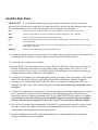
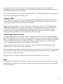
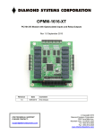
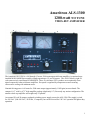
Ameritron ALS-1300
1200-watt NO TUNE
TMOS-FET AMPLIFIER
The Ameritron ALS-1300 is a 160 through 15-meter 1200-watt output solid-state amplifier. An optional userinstalled MOD-10MK filter assembly extends operation to 12- and 10-meters. The ALS-1300 uses eight 50volt conservatively rated linear RF MOSFETS. These 50-volt linear FET’s produce an exceptionally clean
signal compared to other solid-state amplifiers. Fan speed is regulated by temperature sensors assuring
conservative cooling with minimum noise.
Nominal driving power is 90 watts for 1200-watts output (approximately 11 dB gain) on most bands. The
compact 10.5” wide by 6.75” high amplifier package (depth only 19”) fits nearly any station configuration. The
attractive desk-top amplifier unit weighs only 22 pounds.
An external 50-volt 50-ampere regulated switching power supply powers the ALS-1300. The supply is wired
for 240 VAC (200-260 VAC, 50-60 Hz, 15 amperes), but can be rewired for 120 VAC operation for lighter duty
operation.
1
Table of Contents
TABLE OF CONTENTS .......................................................................................................................2
AMPLIFIER FEATURES ......................................................................................................................3
POWER SUPPLY .................................................................................................................................4
Power Line Requirements .....................................................................................................................................................................4
Power Supply Features..........................................................................................................................................................................4
Power Supply Location .........................................................................................................................................................................4
GENERAL INFORMATION ..................................................................................................................5
Amplifier...............................................................................................................................................................................................5
Power Supply ........................................................................................................................................................................................5
INSTALLATION....................................................................................................................................5
Airflow..................................................................................................................................................................................................6
INTERCONNECTION WIRING.............................................................................................................7
AMPLIFIER REAR PANEL ..................................................................................................................8
FRONT PANEL ....................................................................................................................................9
OPERATION.......................................................................................................................................10
MARS OR CAP OPERATION ............................................................................................................11
INITIAL OPERATION .........................................................................................................................12
CIRCUIT BOARDS.............................................................................................................................14
TECHNICAL
INFORMATION………………………………………………………………………….…………………….26
2
Amplifier Features
This amplifier provides the following standard features:
•
Eight conservatively rated, very linear 50-volt MOSFET transistors
•
Operational in a few seconds. No long filament warm-up time
•
Clean layout with easy-to-service modular construction
•
Front panel LEDs indicate band, faults, ALC and transmitting status
•
Quiet variable-speed forced air cooling system
•
Power amplifier module balance metering
•
Power amplifier module current and voltage metering
•
PEP forward power and PEP reflected power metering
•
Reflected power protection
•
Bandswitch error protection
•
Standard negative going ALC output with front panel adjustment
•
ALC metering and an ALC LED indicator
•
5 milliseconds receive-to-transmit relay switching
•
Adjustable Forward and Reflected peak meter hold time
•
Adjustable meter brightness
•
Fully regulated external power supply
•
Compact size 19” deep x 6.75” high x 10.5” wide
•
Weight amplifier section 23 pounds
Options
•
MOD10-MK: Enables 12/10 meter operation. User-installed.
•
QSK-5 PIN Diode Switch for silent QSK operation
•
ARI-500 Amplifier Radio Interface for auto band-switching with your transceiver
3
Power Supply
The power supply for the ALS-1300 is a voltage regulated current limited supply. It contains 14-volt positive
and negative supplies as well as dual 50-volt 25-ampere continuous (30-ampere peak) fully current limited
supplies. Each PA (power amplifier) module in the ALS-1300 operates from the separate 50-volt sources,
giving a total dc input power rating of 2500 watts to the power amplifier modules.
Power supply to amplifier interconnections are through a heavy-duty cable using a large Cinch Jones connector.
Power Line Requirements
This amplifier ships wired for 200-260 Vac. The maximum average power line current is 12 amperes at 240
volts. Two 250-volt 15-ampere fuses fuse the power line.
Note: 120-volt power mains operation is possible with a reduction in CW or RTTY power. Because average
power is very low, SSB operation is minimially affected by 120 volt operation. Fuse size should be 25 amperes
maximum at 120VAC.
Power Supply Features
•
Efficient operation from 200-260 volts ac (12 amperes minimum) and 100-135 volts (20 amperes
minimum)
•
Wide range of power line frequencies, 40-400 Hz
•
Fully regulated current-limited outputs
•
Step-start to limit stress on power supply components
•
Exceptional filtering and RFI suppression
•
Compact size 13.25” deep x 6.75” high x 10.5” wide
•
Light weight design 15 pounds
Power Supply Location
Locate the power supply in a convenient ventilated area near the amplifier location. Do not place the power
supply next to sensitive equipment like audio processors, transceivers, or microphones. For safety, ground the
wing nut stud on the supply rear to your station ground buss. The station ground buss should comply with
national electrical codes. These codes dictate that station grounds must be bonded to the power mains entrance
ground. A station ground that is not bonded to the mains ground does not offer lightning protection!
4
General Information
Amplifier
The Ameritron ALS-1300 is a solid-state 1200-watt nominal RF output power 1.8-22 MHz amplifier (1.8-30
MHz with optional MOD-10MK). This power is peak envelope power, which is the same as actual carrier
power on CW. The ALS-1300 uses eight exceptionally low-distortion push-pull parallel MRF-150 or equivalent
RF power TMOS transistors. The ALS-1300 meets or exceeds all FCC rules governing amateur radio external
power amplifiers.
Two temperature sensors on each PA (power amplifier) module track FET and heatsink temperatures and
provide fan speed control for heatsink cooling as well as FET bias control.
Harmonic suppression comes from push-pull operation of linear devices, and a series of high quality 5-pole
low-pass filters. This amplifier exceeds all FCC mandated harmonic requirements.
Antenna switching is through a sequenced pair of miniature relays on a plug in board. Relay switching time is
approximately five milliseconds. The ALS-1300 “relay” jack sources 12 volts when open circuit, and the relay
jack current upon closure is less than 20 mA. Note: Five milliseconds is fast enough for QSK operation. Due to
mechanic relays and relay noise, Ameritron still recommends the Ameritron QSK-5 T/R Switch for QSK
operation. The QSK-5 uses Pin Diodes that switch much faster and quieter than relays.
This amplifier includes two dual-movement cross-needle meters. This is the equivalent to having four panel
meters. The left hand meter is a dual power amplifier current meter. The right hand meter continuously displays
forward RF peak envelope power on one dedicated scale, while the second movement is switch selected
between reflected power, combiner mismatch voltage, ALC, and the drain voltage of each power amplifier.
While this amplifier will run more than 1200 watts PEP output, linearity will suffer. Ameritron recommends
running no more than 1200 watts peak power for maximum linearity, where this amplifier will have comparable
IM performance to the best vacuum tube linear amplifiers. The characteristics of linear high-voltage FET’s are
very much like those of triode vacuum tubes.
Power Supply
The ALS-1300 external power supply normally operates from 200-260 volts at 50-400 Hz. It connects to the
amplifier through a single cable. The power supply should be located in a cool spot away from sensitive audio
systems or cables.
Installation
Please look your amplifier and power supply over carefully. Locate the air inlet and outlet areas of the
amplifier. The cooling air inlet is on the right side as viewed from the normal operating position (front view).
The warm air outlet is on the left side of the amplifier. While the outlet air won’t be noticeably warm, it is never
a good idea to have it blow into heat sensitive equipment such as transceivers or other power amplifiers. Have
the same consideration for the ALS-1300 amplifier and power supply. Be sure the air inlet temperature is not
substantially above normal room temperature. Ideally the air inlet temperature should be kept below 32° C or
90° F, although inlet temperatures up to 41° C or 106° F are permissible. If ambient temperatures exceed these
limits it might become necessary to reduce duty cycle or power.
5
Warning: Do not block cooling air inlets and outlets!
Never expose the amplifier to water or mist.
Airflow
The amplifier must have a clear area to the sides and top for proper airflow, and to the rear for interconnection
wiring. It is especially important to avoid obstructions that block the air inlet on the top left and both lower
sides. Two inches of clearance is normally adequate for full ventilation. Keep any papers or loose objects that
might impede airflow away from the air inlets and outlets.
Locate the amplifier and power supply away from sensitive equipment such as microphones, audio processing
equipment, or low level audio or radio frequency amplifiers. Normally the best location for the power supply is
below the operating desk and away from antenna feedlines. This will keep fan noise and any RF coupling to a
minimum.
The power supply is factory wired for 200-260 Vac. It uses a standard NEMA-6-15P 15-ampere 240-volt plug.
The round center pin is the safety ground. Do not remove the safety ground.
CAUTION! Before connecting the power supply to an electrical outlet, always be sure you have completed the
following four steps:
1. Insert the 15-ampere 250V fuses into the two black fuse caps.
2. Insert the fuse and cap assemblies into the power supply’s fuse holders. The fuses lock in place
with a slight turn.
3. Connect the power supply to the amplifier.
4. Be sure the amplifier power switch is turned off.
Caution! Fuses have both voltage and current ratings. Use only 250V rated
fuses in this device. The voltage rating generally is marked on fuses. DO NOT
use automotive-type low voltage fuses in any power line application. For 240volt operation 15-ampere fast-blow fuses are required.
Warning: Never insert the power supply cord into the outlet unless the above
four steps have been completed!!
Position the amplifier at the desired location on your operating desk such that you have access to the rear panel,
and connect the rear panel cables. Do not connect the power mains at this time!
6
Interconnection Wiring
POWER SUPPLY
FUSE
ANTENNA,
ANTENNA
TUNERS,
SWITCHES,
FILTERS
FUSE
ALS - 1300
OUT IN
REMOTE
A
B
RLY
ALC
TRANSMITTER / TRANSCEIVER
ALC
RLY
ANT
INTERCONNECTIONS
Interconnections Figure 1
7
Amplifier Rear Panel
PWR SUPPLY To prevent connecting the power plug wrong, the large black multi-pin connector is
indexed by an offset in the two round pins. One round index hole is closer to the outer connector edge. Mate
the round pins and holes and seat the male plug fully onto the amplifier rear panel pins.
ALC
Optional connection. Connects to radio ALC input. Mandatory if using a radio over 100 watts.
RLY
Connect to radio amplifier keying line. Radio must pull this line below 2 volts to transmit.
GND
Connect to station ground buss. This connection is for safety.
IN
Connect through good 50-ohm coaxial cable to radio’s antenna output connector. This can be a smaller
cable like RG-58/U.
OUT
To 50-ohm antenna, antenna tuner, power meter. This is the high power output. 50-ohm coaxial cable must
safely handle 1200-watts.
REMOTE
Interfaces for optional ARI-500 Amplifier Radio Interface.
1.) Connect the station electrical safety ground to the rear panel wing nuts. National safety codes require the
station ground to be bonded to the power mains safety ground at the building entrance.
2.) Connect the power supply to the amplifier.
3.) Connect the RLY line to the transceiver’s accessory RELAY or XMT port. This port must pull low for
transmit, and be open circuit when receiving. Relay control voltage from the ALS-1300 is 12 volts
positive with only 15 mA current. You should always check your transceiver’s manual, but almost any
standard transceiver directly interfaces to this amplifier.
4.) Connect the OUT (output) port to the appropriate point in your station. This is the high power RF output
cable. This connection would go to your 1500-watt rated Power/SWR meter, antenna, or antenna
matching device. Good quality Mini-8 or RG-8X cables are acceptable for anything but RTTY use,
although larger RG-8 style cables are normally preferred. Your antenna matching system must connect
to this port.
5.) Connect the IN connector to your transceiver. Do not install any active antenna matching devices on this
port. In general short and direct cable connections are best, although high quality cables can be very
long without adversely effecting performance. RG-58/U or Mini-8 (RG-8X) style cables are acceptable.
You should never use a tuner of any type on the amplifier input, nor should you drive this amplifier
with over 100 watts peak envelope power. Never use a non-FCC accepted device with this amplifier.
6.) The ALC line is optional, but recommended. Without ALC you must monitor your drive power so that
you don’t overdrive the amplifier which will cause intermodulation distortion. The ALS-1300 ALC
circuit monitors the RF output power and reflected power.
7.) Operate the bandswitch manually during initial testing. Do not connect band decoders or computer
interfaces until initial tests are completed.
8
Front Panel
Amplifier Front Figure 2
9
Front Panel Operation
Two dual-movement cross-needle meters are illuminated with LEDs
J4 determines the brightness of the LEDs. J4 is located on the MB1 board Fig 8 page 19
Left hand meter (Fig2.1 page 9) is a dual current meter. It monitors current on PA “A” and PA “B”
Right hand meter (Fig 2.2 page 9) continually monitors forward RF peak output on one scale, while the second
scale monitors reflective peak power, combiner mismatch, ALC, and each power amplifier operating voltage.
The forward and reflected meters have a peak hold circuit. This circuit allows the meters enough time to
respond to voice peaks, making it a true peak reading wattmeter. The Peak hold time is adjustable. (Fig 8 page
19). Note: Changing the peak hold time to a faster needle movement will prevent the Forward and Reflected
meters from reading Peak Output Power. It is recommended that you keep the factory default settings.
Band Select Switch (Fig 2.3 Page 9) selects either the correct low pass filter for each band, or remote control
operation. The nine LEDs (Fig2.4 page 9) verify which low pass filter has been selected. Note: The 10 and 12
Meter Band LEDs will illuminate but operation requires the 10/12 meter conversion (MOD-10MK). When
using the external ARI-500 for auto band switching the, Band Select Switch must be in the Remote position.
ALC SET (Fig 2.5 page 9) limits the output of the amplifier to a safe level when the rear ALC Jack is
connected to the transceiver’s ALC input. The ALS-1300 produces an ALC control voltage of 0 to –4 volts DC.
ALC Indicator (Fig 2.6 page 9) illuminates when the ALC circuit begins producing a negative voltage at the
rear panel ALC jack.
SWR Indicator (Fig 2.6 page 9) illuminates when the Antenna VSWR reaches an unsafe level for the
amplifier. When this occurs, the amplifier reverts to Standby. Moving the Standby/Operate switch to Standby
and then back to Operate resets the SWR overload circuit. The VSWR overload circuit will activate at 200
watts reflective power.
PA Indicator (Fig 2.6 page 9) illuminates when there is a mismatch between the two power amplifier modules.
When this occurs, the amplifier reverts to Standby.
SWR and PA LEDs illuminate when the Band Select Switch is in the wrong Position or there is a problem with
the Low Pass Filter circuit. This places the amplifier into Standby.
TX Indicator (Fig 2.6 page 9) illuminates when the rear panel relay jack is grounded. This places the amplifier
into the Operate condition. The transceiver will not receive when this light is on.
Multimeter Switch (Fig 2.7 page 9)
Multimeter switch positions are monitored on the right hand meter, right scale.
REF Monitors reflected power. Meter reading is 0 to 500 watts. SWR is read where the forward and
reflected needles intersect.
PAB Monitors the difference between power amplifier Module A and power amplifier Module B. A
difference of 200 watts will place the amplifier into Standby. Meter reading is the 0 to 500 scale
10
ALC Monitors the ALC voltage on the rear panel ALC Jack. Meter reading is the 0-70 scale which
corresponds to 0 to -7 volts.
HV1 Monitors the operating voltage on the Power Amplifier Module “A”. Meter reads on the 0 to 70
scale. Should read 48-50 volts
HV2 Monitors the operating voltage on the Power Amplifier Module ‘B”. Meter reads on the 0 to 70
scale. Should read 48-50 volts
OPERATE/ STANDBY SWITCH (Fig 2.8 page 9). In Standby, disables the relay line from the transceiver.
The amplifier is bypassed. This allows tuning the antenna or checking the transceiver’s RF power. The Forward
and Reflected meter readings are still operating, fans continue to run and the operating voltage is present when
the power switch is on. In Operate, places the amplifier into transmit when the relay line is pulled low.
ON / Off Switch (Fig 2.9 page 9) When Off, all operating votages, fan and meters are disabled. The amplifier is
in by-pass mode. Note: There is still AC power on the On/off switch. Remove the Power Supply’s line cord
from the power mains before removing the amplifier or power supply cover.
Operation
This amplifier is very simple to operate. Once you have established proper connections please set the amplifier
(Fig. 2, ref 3) to one of the following bands:
Band
160
80
40
30
20
17
15
12
10
Frequency Range
1.8 - 2.1 MHz
3.2 - 4.2 MHz
6.0 - 7.5 MHz
7.5 - 14.0 MHz
13.5 – 14.5 MHz
14.5 – 19.0 MHz
19.0 – 22.0 MHz
22.0 – 25.0 MHz
28.0 – 30.0 MHz
Notes
US domestic power limit is 200 watts maximum
Export Only. Requires user-installed MOD-10MK for US domestic operation.
Export Only. Requires user-installed MOD-10MK for US domestic operation.
Frequency Limits Table 1
Caution: This amplifier is not suitable for 27 MHz operation. Damage to the expensive power amplifier
transistors will occur if attempts are made to use this amplifier in the 25-28 MHz frequency range.
MARS or CAP Operation
For licensed amateur radio operators participating in Military Affiliate Radio Systems, this amplifier is suitable
for MARS and CAP operation on all frequencies between 1.8 and 22 MHz with some precautions. The upper
frequency limits are in bold type in the table above. Do not operate above the bold-type frequency limits in the
table above or PA (power amplifier) damage may occur. It is permissible to operate below those limits if you
provide additional external harmonic suppression for authorized services such as MARS and CAP.
11
When operated outside the frequency limits above, harmonic suppression might not meet acceptable limits. You
may have to use additional external 2nd harmonic filtering. Ameritron guarantees to exceed FCC part 97.307
harmonic suppression standards only inside the frequency ranges listed above. Contact Ameritron with your
specific requirements. Ameritron requires proof of a valid MARS or CAP license as well as your own amateur
radio license for technical assistance.
12/10 Meter Operation
Operation on the 12 meter and 10 meter ham bands requires the installation of the optional MOD-10MK low
pass filter assembly. The MOD-10MK is installed on export models of the ALS-1300, but is NOT included on
amplifiers shipped within the US. Upon proof of a valid US amateur radio license, a MOD-10MK may be
purchased from Ameritron. The MOD-10MK can be installed in the amplifier in minutes using just a Phillipshead screwdriver. Installation instructions are provided with the MOD-10MK.
Initial Operation
Double-check all wiring and connections (fig. 1) before turning power on. It always pays to be safe. If you are
sure you have connected your amplifier correctly, follow the procedures below. The following steps only need
to be done on an initial checkout:
1. Place the MULTIMETER switch (fig.2 ref 7) in the HV2 position. Place the ALC SET control (fig2.
ref 5) fully clockwise (10 on scale).
2. With the STANDBY/OPERATE switch (fig.2 ref 8) on STANDBY, turn the power switch (ref 9) ON.
3. There will be a 3-5 second step-start circuit delay, and then a click as the power supply turns on. HV2
(fig.2, ref 2) should immediately rise to nearly full scale, and after a slight delay you should hear another
click. The meters and BAND LEDS (fig.2, ref 4) will light up.
4. The HV meter (fig.2, ref 2) should read between 48 and 50 volts.
5. Change the meter switch (fig.2 ref 7) to HV1. The voltage should be the same as in step 4.
6. Rotate the BAND switch (fig.2 ref 3) through all positions. For any model purchased in the USA, only
the 160, 80, 40, 30, 20, 17, and 15-meter bands will actually operate. US operation on 12- and 10meters requires the optional user-installed MOD-10MK filter assembly.
7. Change the meter switch (ref 7) to REF. This will read reflected power.
8. Provide a low power (~10 watt) unmodulated carrier from your transceiver using FM, AM, RTTY, or
CW. Verify that the VSWR of the antenna system is low. You should see almost no deflection on the
reflected power scale (fig.1 ref 2). If you see reflected power, check your RF cables or antenna system.
Note: You must not use a tuner in your transceiver or between your transceiver and the ALS-1300
amplifier to match the antenna system. Any antenna matching must be between the amplifier and
12
the antenna, and the antenna tuner must be able to handle at least 1200 watts of carrier or peak
envelope power.
9. Place the amplifier in OPERATE (fig.2 ref 8). Be sure the BAND selected on the amplifier matches the
band selected on the transceiver.
10. Place the transmitter or transceiver into transmit in FM, AM, RTTY, or CW modes. The green TX LED
(fig.2 ref 6) should light. The forward power (fig.2 ref 2) should increase to approximately ten times the
initial reading, the reflected power should remain low, and the PA current should increase slightly on
both scales of the current meter (fig.2 ref 1). No other lights should illuminate.
11. Briefly increase drive power (no more than 100 watts) until the ALS-1300 output is 1200 watts.
12. If ALC is connected between the amplifier and transceiver, rotate the ALS-1300 front panel ALC
control counter-clockwise until the ALS-1300 output power just begins to drop.
13. After you have verified all of this, the amplifier is ready to operate.
Technical Questions:
Call 662-323-8211 or go to www.ameritron.com help desk for operation or technical
questions.
If service is ever needed send product to Ameritron 116 Willow Rd, Starkville, MS 39759. Include a
phone number, email, return address and a brief description of the problem.
13
Circuit Boards
There are ten basic circuit boards plus two power amplifier modules in the ALS-1300. The text below gives a
brief description of each board’s function.
2KWF
The 2KWF is a high power low pass filter. It is the very large board with large toroids and a few air wound
inductors. This board contains filter SWR fault detection, power amplifier unbalance detection, and multiple
high power low pass 5-pole filters. Additionally two smaller boards, the antenna relay board RLY and the PA
combiner board CMB, attach directly to the low pass filter board.
BS1
The BS1 is located behind the BAND switch. It provides all band selection functions as well as band indicators.
CB1
The CB1 is located near the front of the amplifier just behind the meters. The CB1 control board provides most
control functions. This includes bias, fan speed, overload protection, and transmit-receive relay sequencing. It is
the hub for nearly all functions and interfaces.
CMB
This board combines the outputs of the two 600-watt PA modules. It is a traditional 50-ohm “magic T”
combiner with an output-matching transformer.
FL10
The FL10 filter assembly (MOD-10MK) is optional and only appears in export models. It enables 10- and 12meter operation.
MB1
The MB1 is located behind the front panel below the meters. It contains peak-envelope-power detection
circuits, multi-meter switching, fault indicators, and ALC circuits. There are four power meter adjustments on
this board; forward power, reflected power, forward peak hold time, and reflected peak hold time. Shunts on a
header located on the board’s upper edge adjust panel meter brightness.
PA Boards
PA boards are located on top of the heatsinks under the filter-board shield panel. There are no user adjustments
on these boards.
PD8
The PD8 is located on the right side of the amplifier just above the panel containing the cooling fans. It contains
a power splitter and two 5 dB attenuator pads. The splitter and attenuator pads isolate the two power amplifiers
from each other, and terminate the PA inputs in 50 ohms over a wide range of frequencies. This is necessary to
stabilize the PA modules. Do not remove or bypass the attenuators.
14
RJ45
The RJ45 board mounts on the rear panel. It contains two RJ-45 jacks used for remote control operation.
RLY
The RLY board contains two transmit and receive relays - one for RF output switching and the other for RF
input switching. T/R relays activate with a low on terminals K (key) J1-3 and RJ1-7. The CB1 board contains
the relay timing controls.
SWR
The SWR board is on the rear panel in front of the RF output connector. It is a traditional 50-ohm directional
coupler. The null adjustment is accessible through a rear panel hole.
Schematics
Filter 2KWF
2KWF-1R1
081210
PA Comb Out
PA A
PA B
Gimmik
T2
C99
T1
RLY1
C1
1500
D1
1N916
C28
270
R4
10k
C98
10pf
RLY5
C7
680
C10
360
C6
680
L6
12T
C11
C13
C29
270
L9
6.5T
.01
RLY9
C15
C14
270
C17
C19
180
RLY11
FL 10
RLY2
RLY4
C8
680
RLY3
C22
.1
RLY4
C23
.1
RLY6
C24
.1
RLY8
C25
.1
RLY10
C26
.1
RLY12
C27
.1
RLY6
L10
6.5T
RLY5
RLY8
C16
270
C18
180
RLY7
RLY10
J2
180
RLY11
1500
L8
8T
270
12VDC
RLY2
C4
C12
360
360
L7
8T
RLY7
R3
1k
L5
12T
360
1N916
R1
1k
L3
11T
C2
C3
1500 1500L4
11T
C9
50
D2
L2
16T
C5
680
R2
C21
.001uf
RLY3
L1
16T
C20
180
RLY9
RLY12
FL10
J1
Gnd
160
80
40
20
15
10
Gnd
FL 10
RLY11
Ant
Rly
J4
J3
PA Out Rly
PA IN
RADIO
rev 03 Mar 2009
2KWF output filter Figure 3
15
Bandswitch BS1
BS - 1
LED1
160
LED2
80
D1
1N4001
D2
1N4001
80
2
40
D3
1N4001
J1
G
160
80
40
20
15
10
12V
D4
1N4001
J2
D5
1N4001
+12V
Remote
J3
G
160
80
40
20
15
10
12V
D6
1N4001
R1
1k
30
LED3
40
1
3
160
+12V
LED4
30
4
20
LED5
20
5
17
9
6
SW 1
rear
view
7
15
10
12
LED6
17
8
LED7
15
LED8
12
LED9
10
+12V
7 July 2008
BS1 bandswitch figure 4
16
Control Board CB1
CB1 rev2.1 090227
R1
1k
ZD1
J1
G
+
K
F
R
REAR
PANEL
A
TO MB
J1
10k
R58
U4pin8 U4pin4
DC12V
1A
.01
5
6
3
U1B
U1A
G
+
F
R
T
P
S
A
CL
R11
100
R5
100
12
R17
1k
C3
.1
10
11
14
D7
D2
1
R29
27k
R16
4.7k
D4
D6
D5
16
LM358
U4A
3
D9
R28
100
D3
U1D
13
DC12V
C2
.1/50v
7
13
1
CLK5
C1
.1/50v
F2
1A
DC12V
R57
1k
4042
U3
7
2
R2
100
DC12V
8
VR10
25k 40%
R8
1k
S
R4
100
J5
R10
100
R3
100
C4
F1
U1pin4 U1pin11
R59
10k
5.1v
1
Q1
3906
C15
.47
R27
4.7K
D8
R7
1k
C6
.1
C8
.1
R6
100k
6
4.7k
C14
.01/50v
DC12V
C22
.47
R22
1k
R15
10k
R18
10
RL2 ANT
R20
6.8k
Q2
2955
Q3
3904
J2
FILTER
G
CL
S
G
2
1
X
X
C7
.01/50V
Q5
2955
RL1 INP
LM358
U4B
7 R24
5
R9
10k
R21
6.8k
Q4
3904
R26
4.7K
C10
.01
R19
10
R23
1k
4.7k
C16
.1
C9
.1
R12
10k
R25
2
C5
.01
R14
10
RS
T
P
S
S
RJ1
J4
GND
160
BAND
FILTER
F
K
10
GND
S
R13
1k
C13
.1
RL2 ANT
FAN
J7
FA
RL1 INP
C12
.01
J6
STBY
MISC
+
R39
10k
C11
.01
DC12V
R33
4.7k
DC12V
Switched
C25
.1
C24
.1
C23
.1
R34
10k
3
R31
4.7k
R32
10k
FAN
2
C35
.1
U2A
FB
R37
2.2k
Q7
3055
R35
1k
C21
+.47
R38
10k
C26
.1
14
13
G
S
S
X
X
C27
.1
U2D
12
C19
.1
160
BAND SWITCH
FAN
1
R36
2.2k
C18
.1
R30
1k
10
+
Q6
3055
IN
C20
+ .47
U2pin4 U2pin11
R40
4.7k
R41
10k
10
9
U2C
916
D10
OUT
Q9
3906
1k
R52
1k
C17
.1
DC12V
R46
8
U5
LM7809
DC12V
R47
1k
R42
4.7k
5
6
U2B
7
R45
1k
3055
R51
4.7k
Q8
3906
Bias B R50
10K
R44
1k
+
C31
.47
Bias B
Bias A
C34
.1
C29
.1
Bias SW
Bias B
1k 40%
VR3
1k 40% 1k 40%
VR1
VR2
R53
100
Bias A
Q10
3904
+
C30
.47
R55
100
R54
100
+
C33
47/50v
VR5
1k 40%
J8A J8B
HS
FET
1k 40%
VR4
R49
4.7k
R48
10K
Q11
3904
C28
.1
47/50v
C32 +
DC12V
Q12
Bias A
R43
10k
J3
DC12V
VR6
1k 40%
HS
FET
VR7
1k 40%
VR8
1k 40%
C36
.1
R56
100
C37
.1
CB1 control board Figure 5
17
Combiner 2000 watt CMB
CMB 081217 rev0a
T5
T6
50 OHMS
IN
PA A
100
50 OHMS
IN
50 OHMS
OUT
PA B
CMB combiner board Figure 6
Filter FL10
FL10 081210
L1
1
C1
130pF
In
C2
130pF
L2
1
C3
130pF
Out
C4
130pF
FL10 filter 10 meter Figure 7
18
Metering Board MB1
-12V
FWD SPEED
REF SPEED
R15
1m 40%
R5
10k
LM324
R20
4.7k
8V
U1A
3
2
1
C8
R6
1m
.01
R9
10k
5
PIN 1...GND
2...12 3...12 +
4...FWD PWR
5...RFLCTD PWR
6...TRANSMIT LED
7...COMBINER LED
8...SWR LED
9...ALC VOLTAGE OUT
10...COMBINER LVL
CAL
U1B
7
6
11
R18
4.7k
CTRL
J1
D2
1N916
D3
1N916
D1
1N916
4
R16 1m 40%
8V
R2
2.5k 40%
C3
+
2.2
R3
5.6k
C2
.1
D6
1N916
D9
1N916
D5
1N916
R36
1k
R34
220K
-12V
D8
1N916
R37
1k
8V
R17
4.7k
R35
100k
12
13
D4
U1D 1N916
10
14
C9
R8
1M
.01
REF CAL
U1C
R1
2.5k 40%
C1
.1
2.2uF
MULTI METER
R4
5.6k
J2
Gn d
F
+
L
G
+12
R28
10k
C10
R29
1k
1
U2B LM358
8
5
R27
7
6
1k
4
2
R26
560
.1
R33
220k
R39
R30
6.8k
R32
1k
C11
.1
C7
.1
-12V
3
R7
10
V2
C
A
+
SW 1
5
10
A
9
R
8
METER BRIGHTNESS
7
CTRL
R12
10
J1
PIN 1...V2
2...V2
3...V1
4...V1
J4
.1
R25
1k
Gn d
+
Fw d
Ref
T
C
S
A
CL
R11
68K
C13
.1
C
V2
6
CURRENT
J3
CURRENT
J3
V1
C5
C6
.1
R10
68K
11
V1
4
R21
100
R19
10
12
R
2
D4
LED4
R31
1m
D7
1N916
ALC
10k 10%
C12
.1
1
U2A
3
PIN 1...GND
2...FWD
3...MM 4...MM +
5...LMP
6...GND
8
9
+
C4
MULTI METER
J2
+12V
R13
1k
R14
1k
+12V
METER BRIGHTNESS
J4
1,2 low
2,3 high
R38
4.7K
C16
.1
R22
1k
R23
47k
R24
47k
Q2
C15
.1
2N3904
R41
1k
D1
LED3
Q1
C14
.1
2N3904
R40
1k
D3
LED1
C17
.1
MB1 Rev3 090227
PEAK METER / ALC
D2
LED2
MB1 alc/metering board Figure 8
19
PA Module
PAM-600
081217 Revision 0a
Yel
C4
.1uF
C1
Org
00
R2
NTC
C6
.33uF
C7
.33uF
R8
18
18R10
R7
1k
R9
1k
R13
P1
T1
C10
470pF
CONN
C11
330pF
18 R19
Red
t
u
O
A
P
Q2
1 R11
C8
.1uF
n
I
A
P
C3
470pF
Q1
R6
18
C5
.1uF
R1
NTC
C2
.001uF
1 R4
18 R3
.1uF
R5
470
22
R14
22
R15
22
R16
22
R17
22
R18
22
R12
C9
470
.001uF
T3
X1
T2
R21
C13
470
.001uF
T4
C23
.33uF
C24
.33uF
FB2
Q3
1 R20
V1 Red
C12
.1uF
C14
.1uF
R22
18
C16
.33uF
R23
1k
FB1
C21
.33uF
C17
.33uF
C15
R24
18
.1uF
Brn
C22
.33uF
50VDC
C25
.47uF
C26
100uF
R25
1k
18 R26
Q4
1 R27
C18
.1uF
R28
C20
470pF
C19
470 .001uF
PAM power amplifier module Figure 9
Power Divider PD8
100 R7
T2
R2
27
R5
27
Out
Out
R1
200
R3
200
R4
200
T1
R6
200
081126
PD8 rev0
-8db splitter
n
I
PD8 power divider Figure 10
20
Interface Connections RJ45
RJ45 Rev0 090217
Pin8
J1
Pin6
Pin7
-
-
Pin4
Pin3
Pin5
Pin8
Pin2
Pin6
Pin7
Pin1
J2
Pin4
Pin5
Pin2
Pin3 Pin1
R2
560
1/2W
D1
D2
R1
1k
C1
0.1uF
J3
CONN
RJ45 interface Figure 11
Relay Board
RLA 081210
HD1
HD4
PA IN
RADIO
RL4
ANTENNA
PA OUT
RL1
MAY 21, 2008
RLY antenna relay Figure 12
21
WHITE
GREEN
22
White 50V
23
24
Reference figures and drawings
Interconnections Figure 1 ....................................................................................................................................... 7
Amplifier Front Figure 2......................................................................................................................................... 9
2KWF output filter Figure 3 ................................................................................................................................. 15
BS1 bandswitch figure 4....................................................................................................................................... 16
CB1 control board Figure 5 .................................................................................................................................. 17
CMB combiner board Figure 6 ............................................................................................................................. 18
FL10 filter 10 meter Figure 7................................................................................................................................ 18
MB1 alc/metering board Figure 8......................................................................................................................... 19
PAM power amplifier module Figure 9................................................................................................................ 20
PD8 power divider Figure 10................................................................................................................................ 20
RJ45 interface Figure 11....................................................................................................................................... 21
RLY antenna relay Figure 12................................................................................................................................ 21
Meter Wiring …………………………………………………………………………………………………… 22
Power Plug Wiring ………………………………………………………………………………………………23
Power Supply Wiring ……………………………………………………………………………………………24
Tables
Frequency Limits Table 1 ................................................................................................................................. 1110
25
Exhibit V Operational description HO82WUALS13
ALS-1300 Technical and Operational Overview
The ALS-1300 is an amateur radio multiband radio frequency linear power amplifier. This device requires
certification. This device complies with technical standards of CFR Title 47 part 97.317(a) and (b).
General Operation
This linear amplifier covers the 160, 80, 40, 30, 20, 17 and 15-meter amateur bands. Up to 100 watts exciter
power is applied to relay RLY1 on circuit board RLY. When power is on and the standby switch is in the
operate position, and when the rear panel RELAY control line is held low (below 1 volt), exciter power is
routed through RLY1 to the PD8 power divider board.
Power Division
The PD8 power divider board splits the signal path equally between two 600-watt power amplifier modules.
The PD8 circuit board consists of a conventional T power divider, components T2 and R7. This T splits the
signal into two equal level signals. Each signal path has a 5 dB attenuator consisting of high power resistors R1
through R6. The 5-dB attenuators on each output port terminate the T in 50 ohms and provide an additional 10
dB of input port isolation between the two PA modules. With a 50-ohm source, in excess of 30 dB port-to-port
isolation occurs between PA module inputs. A minimum of 16 dB isolation occurs regardless of input port
termination. The attenuators also work in concert with the magic-T to provide a 50-ohm input termination for
each PA module. The 50-ohm termination and input port isolation results in unconditionally stabile PA
modules.
PA Amplifiers
Power amplification comes from two 600-watt power amplifier modules. Each PA module (PAM-600) consists
of four MFR-150 field effect transistors. Each MRF-150 has between 200 mA to 400 mA quiescent current.
Transistor conduction angle is slightly over 180 degrees, providing linear class AB operation. The normal dc
drain operating voltage is approximately 50 volts with four FET’s per module in push-pull parallel. Both
modules employ significant negative feedback to improve linearity and stability. The FET’s have direct
resistive voltage feedback across each individual transistor from drain to gate, as well as push-pull transformer
(T2) coupled feedback common to the push-pull circuit. These feedback circuits improve gain flatness,
linearity, and stability. Push-pull operation, negative feedback, and linear biasing of FET’s provide significant
pre-filter harmonic suppression.
Cooling and Temperature
The four power FET’s in each module mount on a forced-air cooled aluminum heatsink. Four dc fans cool the
heatsink. Two thermistors (R1 heatsink, R2 transistor) sense the temperature of the power amplifier transistors
and their heat sinks. Transistor temperature sensor R2 regulates bias voltage, reducing bias voltage when
26
transistor temperature increases. This bias feedback system keeps transistor quiescent current stable
independent of transistor junction temperatures. These thermistors also feed a comparator that removes drive
when transistor temperature becomes unsafe.
The second set of thermistors, R1, monitor heatsink temperatures. Voltage from thermistor R1 regulates fan
speed, increasing airflow as the heat sink warms.
Combiner CMB
Each PAM-600 delivers a rated maximum of 600 watts peak envelope power into a 50-ohm load. Each PA
module feeds a 50-ohm high power combiner CMB that isolates the two outputs. A 50-watt 100-ohm power
resistor dissipates signal level errors between the PA modules.
Voltage step down transformer T1 senses voltage across combiner dump resistor R1. T1 is located on the
2KWF lowpass filter board. This voltage, representing PA combiner unbalance, appears on the front panel
multimeter as a “PAB” (power amplifier balance) indication. PA unbalance sample voltage also feeds a
comparator on the CB1 control board. This comparator disables the PA in the event the power amplifiers
become significantly unbalanced, and illuminates the PA front panel light.
2KWF Lowpass Filter Assembly
The output of the high power combiner goes into the 2KWF lowpass filter assembly. Power enters through a
directional coupler consisting of T2, C28, 98 and 99, and R2. This system detects power amplifier termination
errors. Any significant error will trip the power amplifiers off. A comparator on the CB1 control board monitors
directional coupler termination errors. Such errors normally come from selecting the wrong filter for the
exciter’s operating band, or having a poor load SWR on the amplifier.
5-pole lowpass filter 2KWF further reduces harmonics. Harmonic levels are significantly below levels
mandated by FCC rules governing amateur radio service.
The CB1 control board contains all protection comparators (U1) and latches (U3). In the event of an operational
fault, latches lock out the amplifier and illuminate a warning light on the front panel. CB1 also contains bias,
relay sequencing, and fan speed controls.
Frequencies above 21.5 MHz are disabled in units sold in the United States and possessions.
SWR
The SWR board is a standard 50-ohm directional coupler. It samples line current and line voltage, vectorially
summing them before detection. The resulting voltages represent forward and reflected power, or mismatch of
the ideal 50 ohm load.
27
AMERITRON
116 Willow Road
Starkville, MS 39759 USA
662-323-8211
LIMITED WARRANTY
Ameritron warrants to the original purchaser that this product shall be free from defects in material or workmanship for one year from the date of
original purchase.
During the warranty period, Ameritron (or an authorized Ameritron service facility) will provide free of charge both parts and labor necessary to
correct defects in material or workmanship.
To obtain such warranty service, the original purchaser must:
(1)
Complete and send in the Warranty Registration Card.
(2)
Notify Ameritron or its nearest authorized service facility, as soon as possible after discovery of a possible defect, of:
(a) the model number and serial number, if any:
(b) the identity of the seller and the approximate date ofpurchase;
(c) a detailed description of the problem, including details on the equipment.
(3) Deliver the product to the Ameritron or the nearest authorized service facility, or ship the same in its original container or equivalent, fully
insured and with shipping charges prepaid.
Correct maintenance, repair, and use are important to obtain proper performance from this product. Therefore, carefully read the Instruction Manual.
This warranty does not apply to any defect that Ameritron determines is due to:
(1) Improper maintenance or repair, including the installation of parts or accessories that do not conform to the quality and specifications of the
original parts.
(2) Misuse, abuse, neglect or improper installation.
(3) Accidental or intentional damage.
All implied warranties, if any, terminate one (1) year from the date of the original purchase.
The foregoing constitutes Ameritron's entire obligation with respect to this product, and the original purchaser and any user or owner shall have no
remedy and no claim for incidental or consequential damages. Some states do not allow limitations on how long an implied warranty lasts or do not
allow the exclusion or limitation of incidental or consequential damage, so the above limitation and exclusion may not apply to you.
This warranty gives specific legal rights and you may also have other rights, which vary from state to state.
28