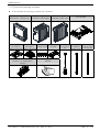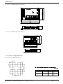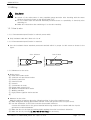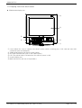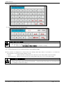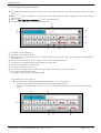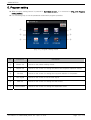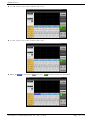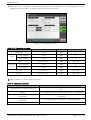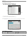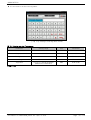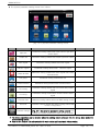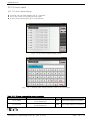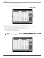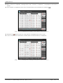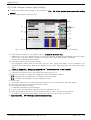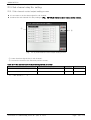
1
Instruction Manual SAMWONTECH ※ This edition is common manual for TEMP2500M, TEMP2700M. Contents Manipulation 1. Safety instruction (Cautions) 1.1 1.2 1.3 1.4 1.5 2. Main screen································································································· Stationary (FIX) operation················································································ Program operation ·················································································· Auto tuning screen ·················································································· Sub channel auto tuning ················································································· Auto tuning and tuning point············································································· 31 32 37 42 47 48 Operation method setting················································································ FUZZY operation ···················································································· Setting data change ratio (SLOPE) operation ························································ 49 51 52 Program setting 5.1 5.2 5.3 5.4 5.5 5.6 6. 26 27 28 Operation related motion setting 4.1 4.2 4.3 5. Basic operation flow chart··············································································· Setting button operation ················································································· How to set the parameters…… ········································································· Setting operation state 3.1 3.2 3.3 3.4 3.5 3.6 4. 3 6 15 24 25 Manipulation and setting 2.1 2.2 2.3 3. Checking the product····················································································· Exterior and how to install··············································································· Wiring ····································································································· Display function and name·············································································· Control part LED ···················································································· Program pattern setting ·················································································· Pattern repetition setting ················································································· File editing ································································································ Time signal operation ···················································································· Standby operation ························································································ Experiment name setting ················································································ 54 61 62 64 67 69 Graph display and saving setting 2nd Edition of TEMP2000M_Series IM : April. 8. 2014 Page 1 / 3 SAMWONTECH 6.1 6.2 6.3 6.4 7. Pattern graph display ····················································································· Measured data (PV) graph view········································································· Setting the measure data (PV) graph saving ························································· SD memory storage setting ············································································· 70 72 74 76 Screen display setting 7.1 7.2 7.3 Screen display setting····················································································· DI error occurrence history view········································································ Heater short state·························································································· 77 79 81 8. Time setting ····································································································· 9. Communication error·························································································· 84 82 System setting 10. System setting 10.1 10.2 Main screen ································································································ System parameter setting procedure ····························································· 85 87 11. Sensor input 11.1 11.2 Sensor input setting ······················································································ Sectional input calibration setting ····································································· 88 94 12. Control & Transmitting output 12.1 12.2 Control output setting ···················································································· Transmission output setting············································································· 96 103 13. DO relay output 13.1 13.2 13.3 Relay No. and parameter setting ····································································· Other signal relay setting ············································································· UP, SOAK, DOWN signal operation ···································································· 105 111 115 14. Communication 14.1 14.2 Communication environment setting (RS232C / RS485)··········································· Communication environment setting (Ethernet)······················································ 116 118 15. Inner signal 15.1 15.2 Inner signal setting························································································ Inner signal operation ···················································································· 119 121 16. ON/OFF signal 16.1 ON/OFF signal setting ················································································· 2nd Edition of TEMP2000M_Series IM : April. 8. 2014 122 Page 2 / 3 SAMWONTECH 16.2 ON/OFF signal operation ················································································ 124 17. Alarming signal 17.1 17.2 17.3 Alarming signal setting ··················································································· Alarming signal operation ··············································································· Heater short alarming signal ·········································································· 125 130 131 18. PID Group 18.1 18.2 PID application scope setting··········································································· PID group setting ························································································· 132 135 19. DI function and operation 19.1 19.2 19.3 DI operation setting ······················································································ DI error name ··························································································· DI error creation screen ················································································· 137 142 145 20. User screen 20.1 20.2 20.3 User screen setting ···················································································· User screen operation ··················································································· BMP file making method·················································································· 146 149 150 21. System initial setting 21.1 Basic screen display setting ············································································ 151 21.2 21.3 State display lamp setting ··············································································· Initial screen operation ·················································································· 153 154 22. Sub channel setting 22.1 Sub channel system parameter setting screen ······················································ 155 22.2 22.3 22.4 22.5 22.6 22.7 22.8 22.9 System parameter setting procedure ····························································· Sub channel sensor input setting ······································································ Sub channel control output setting ···································································· Sub channel relay No. setting ·········································································· Sub channel communication environment setting ·················································· Sub channel alarming signal setting ··································································· Sub channel PID group setting ········································································· Sub channel system initialization setting ····························································· 156 157 162 164 166 168 173 175 * Engineering Units 2nd Edition of TEMP2000M_Series IM : April. 8. 2014 Page 3 / 3 SAMWONTECH 1. Safety instruction (Cautions) Thank you for your choice our multi channel programmable controller (TEMP2000M). This installation manual describes how to install this product. Safety symbol mark (A) “Handle with care” or “Caution” shall be expressed. In case of violation of this point, it may cause the death, heavy injury or severe damage on the device. (1) Product: It is displayed in case that there are points to be recognized certainly to protect the human body and device. (2) Installation manual : The cautions are described in case of the threatening to the life and body due to the electric shock and etc. (B) “Ground terminal” shall be displayed. Make the ground with the ground surface in case of product installation and manipulation. (C)“Supplement explanation” shall be displayed. The information to supplement the explanation is described. (D) “References” shall be displayed. ☞ It describes the points to be referred and the reference page. 음 Cautions in this instruction manual 음 (A) AUTO TUNING shall be delivered for the final user to keep always and it shall be kept in the place within the reach anytime. (B) Use this product after full understanding on the auto tuning. (C) AUTO TUNING is the description on the details of function of the product and the other points besides the auto tuning shall not be warranted. (D) A part of whole part of auto tuning shall not be edited or copied for use. (E) The description in auto tuning may be changed randomly without pre-notice or warning. (F) Even though this auto tuning is made with full effort, it will be appreciated if you inform to the point of purchase (Dealer shop) in case of finding the deficiencies, mistake and omission in the description. 2nd Edition of TEMP2000M_Series IM : April. 8. 2014 Page 1 / 176 SAMWONTECH 음Safety and cautions in the modification(Change)음 음on the product (Change) on the product음 (A) Use this product after full understanding on the cautions (Instructions) for the safety in auto tuning for the protection and safety of the product of the system to be connected for use. (B) Our company is not responsible for the use and handling and every loss incurred due to the negligence without following auto tuning. (C) In case of installing the additional protective or safety circuit for the protection and safe of this product or the system connected this product shall be installed at the outside of the product. The modification (Change) or addition to this product is prohibited. (D) Do not disassemble, repair or modify randomly. It may cause the electric shock, fire and mal operation. (E) Please contact the sales department of our company in case of changing the part or consumables of this product. (F) Do not allow the inflow of the moisture to this product. It may cause a failure. (G) Do not apply strong impact on this product. It may cause the damage on the product or mal operation. 음For exemption of their product음 (A) Our company is not responsible for any warrant or liabilities on the product except the contents defined in quality assurance condition of our company. (B) Our company is not responsible for any direct or indirect damage to the user or third party due to the unexpected defect and natural disaster in use of this product. FFor the quality insurance condition of this product (A) The warrant period of the product shall be 1 year from the date of purchasing and it shall be repaired in free of charge in case of the failure created from the normal use defined in auto tuning. (B) The repair by the failure created after the warranty period of the product shall be processed in real cost (Payment) according to the defined condition by our company. (C) The following cases are processed in real cost even it is the failure created within the warranty period. (1) Defect by the mistake and fault of the user. (Ex : Initialization due to the loss of the password and etc) (2) Failure by the natural disaster(Ex : Fire and flood and etc) (3) Failure by the movement after the product installation (4) Failure by the random disassembly, change or damaged on the product (5) Failure by the abnormal electric source such as the instable electric power. (6) Others (D) Please contact the point of purchasing and sales department of our company in case of necessity for after sales service due to the failure. 2nd Edition of TEMP2000M_Series IM : April. 8. 2014 Page 2 / 176 SAMWONTECH 1.1 Checking the product ▶ Check whether there is no damage on the product by inspecting on the exterior when the product is accepted. In addition, check the following points. 1.1.1 Check the specification of the ordered product ▶ Check whether the accepted product is same with the ordered specification. How to check: Check the model name specification code on the right of packing box and label on the left of product case. ⊙ TEMP2□00M - 0□/□/□/□/□ ① ②③④⑤⑥ No. Name ① Model ② I/O Board ③ SD card option ④ Communication option ⑤ ⑥ HBA option TEMP2000M Sub channel Symbol Description 5 Screen display part 5.7 inch 7 Screen display part 7.5 inch 0 I/O1 (Relay 12point / Basic) 1 I/O1, 2 (Relay 32point) N None SD SD Card RS RS232C, RS485 (Basic) CE Ethernet N None A 50A B 100A C 12A CH2 2 Channel CH4 4 Channel CH6 6 Channel ⊙ Sub channel -□/□ ①② No. ① ② Name HBA option (INPUT 1) HBA option (INPUT 2) Symbol Description N None A 50A B 100A C 12A N None A 50A B 100A C 12A 2nd Edition of TEMP2000M_Series IM : April. 8. 2014 Page 3 / 176 SAMWONTECH 1.1.2 Check the packing contents ▶ Check whether the following contents are contained. TEMP2000M_SERIES Main body – display part TEMP2000M_SERIES CONTROL PART-Main SD CARD I/O2 BOARD (In case of (In case of Fixing mount option selection) option selection) SMPS (Product for independent selling) TEMP2000M_SERIES CONTROL PART-Sub Cable (2m) End bar PC⇔control part I/O1 BOARD Cable (1m) Cable (3m) CONTROL DISPLAY PART PART⇔I/O1 ⇔control part Manual 2nd Edition of TEMP2000M_Series IM : April. 8. 2014 Page 4 / 176 SAMWONTECH 1.1.3 Processing of the damaged product ▶ Contact to the point of product purchase or sales department of our company when the product is damaged at the external inspection on the product as in the above or omission of the parts. Exchange period for the parts with life span ▶ Check the corresponding exchange period for the following life span parts and exchange before passing the exchange period when it is necessary. ■ RELAY ■ BATTERY JQ1P-DC18V, ALD18V equivalent : Under 300,000 times of ON/OFF CR2030 3V equivalent : Under 200,000 hours (A) Contact to the point of product purchase or sales department of our comp for the exchange of the life span parts. 2nd Edition of TEMP2000M_Series IM : April. 8. 2014 Page 5 / 176 SAMWONTECH 1.2 Exterior and how to install 1.2.1 Installation location and environment ACautions in installation location and environment u (A) Handle after switching on at the state of installing this product on the panel because there is a risk of electric shocking. (Cautions for electric shocking) (B) Do not install this product at the following location and environment. ■ A place where a person can touch the terminal point without recognition ■ A place exposed directly to the mechanical vibrato or impact ■ A place exposed to the corrosive gas or combustible gas ■ A place with big temperature change ■ A place with excessive high (Over 50℃) or low (Under 10℃) temperature ■ A place exposed directly to the direct sunlight ■ A place influenced by electromagnetic wave ■ A place with high humidity (A place over 85% of ambient humidity) ■ A place where the flammable stuffs are placed at the surrounding. ■ A place with many dust or salts ■ A place exposed to the ultra violet light ☞ Even though the case of this product is made of non-flammable material such as ABS/PC, do no install at the place where the flammable stuffs exist. 음Cautions in installaiton음 (A) Do not place the device or wire which become the cause of the noise near to this product (B) Use the product within 10~50℃, 20~90% RH(The dew shall not be made). Especially, do not place the excessive heating device at near (C) Do not install the product in declining. (D) Keep the product within -5~70℃, 5~95%RH (The dew shall not be made). (E) Especially, use after full warming up when it is used in under 10℃. (F) Make wiring after switching off of every device during the wiring (Cautions in electric shock) (G) This product operates in 24V DC, 22VAmax without special manipulation. There is a risk of the electric shock and fire when it is used in the abnormal electric source (H) Do not work with wet hand. There is a risk of the electric shock. (I) Keep the basic cautions to reduce the fire, electric shock and risk of injury in use. (J) Install and use according to the instructions on the installation manual. (K) Refer to the installation instruction for the necessary information for the ground. However, do not ground to the water pipe, gas pipe, phone line and lightening rod. There is a risk of explosion and ignition. (L) Do not switch on before connection of the devices of the product. It may cause the failure. (M) Do not close the ventilation hole on the product. It may cause the failure. (N) Do not decline the I/O BOARD and install inside the hygrostat. Use after fixing on the holes on the board with bolts and nuts. (O) The level of excessive voltage is category Ⅱ and the use environment is DEGREEⅡ. 2nd Edition of TEMP2000M_Series IM : April. 8. 2014 Page 6 / 176 SAMWONTECH 1.2.2 External dimension (Unit: mm) G B E H 1.2.2.1 External dimension of display part for each model H D C A F Unit : mm Model Name A B C D E F G H TEMP2500M 144 144 6.5 33.5 136.5 136.5 156 75 TEMP2700M 203 180 6.8 38.2 172.5 195.5 192 75 100.8 Main unit 2nd Edition of TEMP2000M_Series IM : April. 8. 2014 25.5 100.8 4.2 51 4.2 96 96 1.2.2.2 External dimension of control part Sub unit Page 7 / 176 SAMWONTECH 104.6 115 1.2.2.3 I/O1 BOARD external dimension 34.7 170 180 74 94 1.2.2.4 I/O2 BOARD external dimension 29 124 132 1.2.3 Panel cutting dimension ▶ In case of general attaching ※ Panel cutting dimension for each model Unit: mm 2nd Edition of TEMP2000M_Series IM : April. 8. 2014 MODEL A B C TEMP2500M 137.5 137.5 250 TEMP2700M 196 173 308.5 Page 8 / 176 SAMWONTECH 1.2.4 How to attach mount 1.2.4.1 How to install display part ▶ TEMP2000M DISPLAY UNIT panel installation method Fixing Phillips screwdriver Insert DISPL Panel (Refer to the panel cutting dimension) The installation of fixing mount on the left, right, upper and lower part of display doesn’t matter. Panel thickness: 2~7mm ① Cut the panel to be installed. [Refer to 1.2.3 panel cutting dimension] ② Insert the product on the installation hole from the rear side of the main body as shown in the above diagram ③ Fix the main body using the fixing mount on the upper and lower power of the main body (It is same with the picture) (User the screwdriver) ▶ In case of installing with VESA mount ☞ VESA dimension (75*75) is same in every product. 75 VESA dimension (75*75) ※ Cautions Apply M4*4L ~ 6L bolt in fixing on vesa hole . 75 2nd Edition of TEMP2000M_Series IM : April. 8. 2014 Page 9 / 176 SAMWONTECH 1.2.4.2 How to install control part 35 27 ▶ In case of installing DIN rail 1) DIN rail preparation 1 7.3 2) Insert the ⓐ part on the main unit and sub unit into the rail first as shown in the picture and push ⓑ part and the installation shall be made the latch to lock into the rail as shown in the picture. Latch ⓐ ⓑ Push BACK COVER 3) Assemble the installed main unit and sub unit to the direction of arrow as shown in the following picture. 2nd Edition of TEMP2000M_Series IM : April. 8. 2014 Page 10 / 176 SAMWONTECH 4) Both ends of unit is fixed with end bar when the main and sub units are installed not be moved. End bar How to assemble the end bar Firstly insert the end bar onPush up the end bar to arrow direction the upper side of rail 2nd Edition of TEMP2000M_Series IM : April. 8. 2014 Fasten the screw. Page 11 / 176 SAMWONTECH ▶ In case of installing on the wall directly, 1) Disassemble the back cover of main and sub unit as follows. Sub unit Main unit Sub unit Back cover Main unit Back cover ② Pulling ① pushing ① Pushing ② Pulling ▪ Disassemble the back cover by pulling part ②after pressing part ① of main unit. ▪ Check the space to install in consideration of external dimension of screw hole and back cover. 2) Check the space to install in consideration of external dimension of screw hole and back cover. Sub unit back cover 51 25.5 25.5 2nd Edition of TEMP2000M_Series IM : April. 8. 2014 24.87 76.6 100.2 76.6 100.2 Main unit back cover Page 12 / 176 SAMWONTECH 3) Assemble back cover and fix on the wall with screw. M3X12 Main unit BACK COVER Fastening torque recommended for screw 0.3 N∙m(3㎏f∙㎝) Sub unit BACK COVER ▪ Be cautious for the foreign material not to be put into the connector in case of fixing the back cover on the wall. (Possibility of communication connection fault) ▪ Be cautious for the exposed board surface not to be scratched or damaged. 4) Insert the upper part of the main and sub body on the main/sub back cover and assemble for hook to be locked fully by pushing the lower part. Main unit Main BACK COVER ASSY Sub unit Sub BACK COVER ASSY PUSH Main body PUSH Sub body ▪ Check whether the hook is fully assembly after assembling the product main body to the back cover assembly. - There is a big possibility of communication/function disorder when it is incompletely assembled. 2nd Edition of TEMP2000M_Series IM : April. 8. 2014 Page 13 / 176 SAMWONTECH 5) Fix by inserting the fixing unit for each unit not to be separated as shown in the figure. Fixing unit 2nd Edition of TEMP2000M_Series IM : April. 8. 2014 Page 14 / 176 SAMWONTECH 1.3 Wiring Cautions ▶ Switch off the main power of every supplied gauge and wire after checking with the tester whether the electric power on the wiring cable is on. ▶ Do not contact with the terminal absolutely because there is a possibility of electricity after switching on. ▶ Make wire connection after switching off on the wire certainly. 1.3.1 How to wire 1.3.1.1 Recommended specification for electric power cable ▶ Vinyl insulated cable KSC 3304 0.9~2.0 ㎟ 1.3.1.2 Recommended specification for terminal ▶ Use the insulated sleeve attached pressured terminal which is proper for M3 screw as shown in the figure. Over 3.0mm Under Φ5.8mm Under Φ5.8mm Over Φ3.0mm 1.3.1.3 Measure for the noise ▶ Noise source (A) Relay and contact point (B) Solenoid coil and solenoid valve (C) Electric power line (D) Induction load (E) Inventor (F) Commutator in motor (G) Phase angle control SCR (H) Wireless communication device (I) Welding machine (J) High pressure ignition device and etc (K) ▶ Measure for the noise Make the wiring in cautious about the following points for the noise creation source. (A) Make wiring with leaving gap between electric circuit and ground circuit for input circuit. (B) Use the shield wire for the noise from the electrostatic induction. Connect the shield wire to the ground terminal with using caution not to contact with the 2 point ground as occasion demands. (C) Make the wire for the input by twisting tightly against the noise from electric induction. (D) Make the wire by referring [1.3.3.5 Use of sub relay] as necessary. 2nd Edition of TEMP2000M_Series IM : April. 8. 2014 Page 15 / 176 SAMWONTECH 1.3.2 Terminal layout 1.3.2.2 TEMP2000M display part terminal Electric power (24V DC) Ethernet COM1 Connect display part and connection part to PC (Ethernet) COM1 Display part, control part and connection part COM2 Display part and PCconnection part (RS485) 1.3.2.3 Control part terminal COM1 Display part, control part and control HBA1, 2 + - COM2 I/O board, control part and connection + - OUT1 (SSR,SCR,RET) OUT2 (SSR,SCR,RET) + + - OUT1 (SSR,SCR,RET) OUT2 (SSR,SCR,RET) A HBA b Sub unit INPUT1 B A Electric power (24V DC) + - 2nd Edition of TEMP2000M_Series IM : April. 8. 2014 Main b + unit INPUT B- A b Sub unit INPUT2 B Page 16 / 176 SAMWONTECH 1.3.2.4 I/O1 BOARD terminal DI1 DI2 DI3 Electric power (24V DC) + I/O1 LINK DI4 DI5 DI6 DI7 DI8 Communication terminal DI9 DI10 DI11 DI12 DI13 DI14 DI15 DI16 COM COM RLY12 RLY11 RLY10 RLY9 COM NO NO NO NO RLY12 RLY11 RLY10 RLY9 COM COM NC NC NC NC COM RLY8 RLY7 COM RLY6 COM RLY5 COM RLY4 COM RLY3 COM RLY2 COM RLY1 COM COM 1.3.2.5 I/O2 BOARD terminal COM COM COM COM COM COM RLY27 RLY28 RLY29 RLY30 RLY31 RLY32 I/O2 LINK RLY26 RLY25 RLY24 RLY23 RLY22 RLY21 RLY20 RLY19 RLY18 RLY17 RLY16 RLY15 RLY14 RLY13 COM COM COM COM COM COM COM COM COM COM COM COM COM COM 2nd Edition of TEMP2000M_Series IM : April. 8. 2014 Page 17 / 176 SAMWONTECH 1.3.3 Electric power wiring ▶ For electric power cable, make wiring using the cable with equivalent performance of vinyl insulation cable (KSC 3304). ☞ Wiring method for electric power of each unit Communicati on cable (MP0310AS) 24V DC(+) 24V DC(-) Communicati on cable (MP0310AS) 24V DC(-) 24V DC (+) ☞ Electric power 24V DC I/O BOARD 220V AC 2nd Edition of TEMP2000M_Series IM : April. 8. 2014 Page 18 / 176 SAMWONTECH Wiring method for electric power control unit of each unit 24V DC 1.3.3.1 Measured input (ANALOG INPUT) wiring ▶ Switch off the electric power and external power supply on the main body of TEMP2000M certainly in case of wiring the measurement input because there is a risk of electric shock. ▶ Use the shield attached input wire. Make one point ground for shield. ▶ Make the wiring for the measurement input signal line with leaving the gap from the electric power circuit or ground circuit. ▶ Use the electric cable with less cable resistance and cable with no resistance difference among 3 lines. (A) Temperature measuring resistor input (RTD INPUT) SHIELD RTD The 3rd class (B) DC VOLTAGE INPUT (C) DC CURRENT INPUT SHIELD SHIELD + V The 3rd class 2nd Edition of TEMP2000M_Series IM : April. 8. 2014 R DCmA The 3rd class Page 19 / 176 SAMWONTECH 1.3.3.2 Control output (ANALOG OUTPUT) wiring ▶ Connect using caution for the output polarity. The wrong connection becomes a reason of the main body. ▶ Use the shield attached cable for output wiring. In addition, make one point connection for the shield. (A) Electric voltage pulse output (SSR) SHIELD OUT1+ + OUT1- - Control panel The 3rd class OUT2+ OUT2- SSR : 24V DC(12V DC min, 600Ω min) (B) Current output (SCR) SHIELD OUT1+ + OUT1- - Control panel rd The 3 class OUT2+ OUT2- SCR : 4~20mA DC, 600Ω max (C) Transmitting output (RET) SHIELD OUT1+ + OUT1- - Receiver (Recorder and etc) The 3rd class OUT2+ OUT2- 4~20mA DC, 600Ω max 2nd Edition of TEMP2000M_Series IM : April. 8. 2014 Page 20 / 176 SAMWONTECH 1.3.3.3 3 Output (Relay) wiring for external connection point ▶ Please switch off the electric power and power supply to outside from the TEMP2000M main body certainly in case of wiring the external contact point output because there is an electric shock risk. ▶ Connecting point output (RELAY) : NORMAL OPEN under 30VDC 1A, under 250VAC 1A Under 30V DC 1A, under 250V AC 1A Under 30V DC 1A, under 250V AC 1A RLY1 RLY13 COM COM RLY2 RLY14 COM • • • COM • • • I/O1 BOARD Under 30V DC 1A, under 250V AC 1A I/O2 BOARD NO(NORMAL OPEN): Under 30V DC 1A, Under 250V AC 1A NC(NORMAL CLOSE):Under 30V DC 1A, Under 250V AC 1A RLY9_NC RLY11_NC RLY9_NO RLY11_NO RLY10_NC RLY12_NC RLY10_NO RLY12_NO COM COM I/O1 BOARD I/O1 BOARD 1.3.3.4 Input wiring for contact point (DI) ▶ Use the dry contact point for the external connection point (Relay contact point). ▶ Use the dry contact with sufficient opening and closing capacity for the terminal voltage (About 5V) in case of OFF and electric current (About 1mA) in case of ON. ▶ Use the both terminal voltage under 2V, and under 100μA of leak current in case of contact point ON when the open collector is used. Relay contact point input Transistor contact point input DI1 DI1 DI2 DI2 • • • DI16 DI_COM • • • DI16 DI_COM I/O1 BOARD 2nd Edition of TEMP2000M_Series IM : April. 8. 2014 I/O1 BOARD Page 21 / 176 SAMWONTECH 1.3.3.5 Use of sub relay ▶ ON/OFF the load with use of sub relay in case that the resistance load exceeds the relay specification. ▶ In case of using the inductance (L) load such as the sub relay and solenoid valve, insert the CR filter (In using AC) or diode (In using DC) by constituting the surge suppressor circuit for spark removing certainly because it becomes a reason for mal operation and relay failure. ▶ Recommended CR filter ☞ Sungho Electronics : BSE104R120 25V (0.1μ+120Ω) ☞ HANA PARTS CO : HN2EAC ☞ Songmi Electric Co: CR UNIT 953, 955 etc ☞ Jiwoel Electric Manufacturing Co:: SKV, SKVB etc ☞ Shinyoung Communication Co :: CR-CFS, CR-U etc ① In case of DC relay ※ RELAY (Use the relay coil with capacity under the contact point capacity.) Gauge External DC current DIODE (Direct connect to the relay coil terminal) R ② In case of AC relay ※ RELAY (Use the relay coil with capacity under the contact point capacity.) ~ R 2nd Edition of TEMP2000M_Series IM : April. 8. 2014 CR filter (Direct connect to the relay coil terminal.) Page 22 / 176 SAMWONTECH 1.3.3.7 Display part communication wiring method 15 ~ 20 mm (Minimum marginal dimension in case of cable connection) 2nd Edition of TEMP2000M_Series IM : April. 8. 2014 Page 23 / 176 SAMWONTECH 1.4 Display function and name ▶ TEMP2000M display part ④ ⑤ ③ ⑥ ② ① ① Cover (When the cover is opened, the electric power switch, inserting part of SD card and mini USB connection part are displayed.) ② TEMP2000M display part electric power switch ③ SD CARD insertion part (Use for SD CARD option.) ④ LED (The yellow lamp is ON when the first electric power is ON) ⑤ Screen display part ⑥ MINI USB (Use by the user is impossible.) 2nd Edition of TEMP2000M_Series IM : April. 8. 2014 Page 24 / 176 SAMWONTECH 1.5 Control part LED ▶ COM1 LED blinks when the communication between display part and control part are connected. ▶ COM2 LED blinks when the communication between control part and I/O1 board is connected. ▶ MV LED blinks depending on the control output for temperature. (A) Main unit LED displaying the communication between display part and main unit. Main and I/O1 BOARD communication display Main output display LED Electric power display LED (B) Sub unit LED for displaying the OUT1 output LED for is playing the communication between main unit and sub unit LED for display the OUT2 output LED for displaying the electric power 2nd Edition of TEMP2000M_Series IM : April. 8. 2014 Page 25 / 176 SAMWONTECH 2. Manipulation and setting ▶ This produce is composed of dialogue style screen in touch screen method and it is a programmable controller designed easy for use by the customer. 2.1 Basic operation flow chart ▶ When the electric power is ON after the installation of the product, the initial screen is displayed sequentially and it converts to the program stop screen automatically. ☞ It takes about 22 seconds for screen loading. ▶ When the (main) button is pressed on the right upper most at the program stop screen, it converts to the main screen. ☞ Refer to the [21. System initial setting]을 for initial screen change. Logo display screen Main screen 2nd Edition of TEMP2000M_Series IM : April. 8. 2014 Initial screen Program Stop Screen Page 26 / 176 SAMWONTECH 2.2 Setting button operation ▶ Basic setting buttons are shown in [Table 2-1]. Table 2-1. Basic setting button Button type Button operation Touch the ‘Setting Data” in the stationary stop/operation screen and it is used for setting the wanted setting data by the user. The “Pattern No.” part shall be touched in the program still screen and it is used for setting the wanted pattern No. by the user. It is used for inputting the general number and name. It is used for selecting one of the many types. It is used for setting the segment operation time and etc. It is used for selecting one of 2 ~ 3 parameter settings. (ON state / OFF state / Inactive state) It is used for selecting the use or non-use of the corresponding parameter. (ON state / OFF state / Inactive state) It is used for general screen conversion. It is used for the increase and reduction of the page on the same screen. It is used for the page conversion by the increase or reduction of the time axis on the same screen. It moves to the beginning and end of the PV graph page displayed on [6.2 Measurement data (PV) graph view] It is used for moving the PV display axis up/down of the PV display axis in [6.2 Measurement data (PV) graph view] 2nd Edition of TEMP2000M_Series IM : April. 8. 2014 Page 27 / 176 SAMWONTECH 2.3 How to set the parameters ▶ The following setting data input key is displayed and the necessary data can be input when the is clicked at the basic setting button in the above [Table 2-1] ▶ The error message (“LIMIT ERROR”) is appeared on the input data display window with error sound (”Beep”) when the data out of the setting range is input. ① Input key for setting the number ② Input key for setting the pattern experiment name and DI error name. ☞ Refer to the [19. DI function and operation setting] for DI error name input key. ③ Input key for time signal setting. ④ Input key for SEG alarm setting. 2nd Edition of TEMP2000M_Series IM : April. 8. 2014 Page 28 / 176 SAMWONTECH ⑤ User tag input key ⑥ Display in case out of the setting range Touch key lock release ▶ Input after in OFF (Lock release state) of “Key lock” because the setting data is not input when the “Key lock” is “ON (Locked state) A. Refer to the [4. Operation motion setting] for details of setting. 2.3.1 Effectiveness of the setting button and setting data ▶ This product is designed as follows when the setting data input button is pressed or to check the effectiveness of the input setting data by sound. ☞ “Beep” : When the basic setting button is pressed or the setting data is input normally ☞ “Beep and beep”: When the input data by the setting data input key is out of the input range. Cautions in manipulation ▶ Do not press with the sharp thing (Pencil and etc) or excessive power when the basic setting button and setting data input key are pressed. It may become the reason for the malfunction or damage on the touch panel. 2nd Edition of TEMP2000M_Series IM : April. 8. 2014 Page 29 / 176 SAMWONTECH 2.3.2 Setting data input method. ▶ The input data used in product is set by the setting data input key, test name input key and time signal input. ▶ When button in [Table 2-1] is pressed, the setting data input key is appeared, the data to be set can be input. ▶ Refer to [5.4 Time signal operation] for time signal input key. ▶ Function and explanation of setting data input key ⑩ ① ② ③ ④ ⑤ ⑥ ⑦ ⑧ ⑨ ① It displays the "Parameter." ② It displays the “Setting range.". ③ When the setting range is out of the “Setting data display window", the error message (“LIMIT ERROR”) is displayed. ④ It is used when it returns to the original screen after stopping the input. ⑤ It returns to the original screen after saving the input data. ⑥ It is used to input the decimal point. ⑦ It is used to input the sign (+/-). ⑧ It is used to change the input data, the input data is erased by a single character. ⑨ It is used to erase all input data. ⑩ It displays the previously input setting data. Ex) Setting data input method ▶ The method to change the setting data 49.4 into -12.5 is as follows. → Press the setting data input button on the corresponding screen. → Press the corresponding figures (①→②→③→④→⑤) in sequence, and press “ENTER” key(⑥) finally. ③ ⑤ ② ④ 2nd Edition of TEMP2000M_Series IM : April. 8. 2014 ① ⑥ Page 30 / 176 SAMWONTECH 3. Setting operation state 3.1 Main screen ① ③ ② ⑤ ④ ⑥ [그림 3-1] 메인화면 No. Instruction Description ① Graph & Storage It moves to the screen to set the use/non-use of the graph display, graph recording and SD recording use. ② OPER. SCREEN It moves to the stop/operation screen. ③ FUNCTION&FIX It moves to the function and operation method setting screen. ④ PROGRAM SET It moves to the program setting menu screen. ⑤ RESERVE SET It moves to the current time, appointed operation time setting screen. ⑥ DISPLAY SET It moves to the screen for setting the screen brightness adjustment, PV font, buzzer sound use/non-use and backlight electricity saving. 2nd Edition of TEMP2000M_Series IM : April. 8. 2014 Page 31 / 176 SAMWONTECH 3.2 Stationary (FIX) operation 3.2.1 Stationary operation the 1st still scree ▶ Select the operation method in “Stationary” in [4. Operation related motion setting]. ▶ When “Operation state screen” is selected in [3.1 Main screen], it converts to “Stationary operation the 1st still screen.” ▶ The following is the screen for 6 channel of sub channel. [Fig. 3-2] Stationary operation the 1st still screen ▶ When the ‘Setting data” is touched for setting data input, the input key is displayed. ▶ When the “Setting” is touched in the sub channel, the input key is displayed. [Fig 3-3] Setting data input screen Table 3-1. Stationary still screen parameter Parameter Setting range Setting data (SP) EU(0.0 ~ 100.0%) Unit Initial data EU EU(0.0%) ※ EU : Sensor input data range ☞ Refer to [Engineering Unit] 2nd Edition of TEMP2000M_Series IM : April. 8. 2014 Page 32 / 176 SAMWONTECH 3.2.2 Stationary operation the 1st operation screen ▶ It is the screen for measured data, setting data, control output quantity and lamp operation state. ▶ The setting data input key is displayed when the “Setting data” is touched during operation. ① ⑧ ② ⑨ ⑩ ③ ④ ⑤ ⑪ ⑫ ⑥ ⑦ ⑬ ⑭ ⑮ [Fig. 3-4] Stationary operation the 1st operation screen -1 ① It displays the current operation status. . ② It displays current setting data. ③ It displays the current measured data. ④ It displays the current setting data of the sub channel. ⑤ It displays the current measured data of the sub channel. ⑥ The “ON” state of the state lamp is displayed in red and “OFF” state is in dark grey. ☞ The state lamp can be set in [Fig. 21-3 System initial setting screen]. ⑦ The No. of PID group is expressed which is being adopted currently. ☞ The adopted PID group can be checked in [18. PID group]. ⑧ It displays the current date/time and the LCD screen is OFF when it is pressed. ☞ The red lamp is ON when the date/time button is pressed in the operation still screen. ☞ The green lamp is ON when the date/time button is pressed on the operation screen. ⑨ It moves to the [Fig. 3-1 Main screen]. ☞ The key pad to input the password is displayed in case of main button restriction setting. ⑩ It moves to the next screen from current screen. ⑪ It performs or releases the auto tuning with current setting data. ☞ The Y/N of the tuning button display can be set in [18. PID group]. ⑫ The main, sub (Sub channel) is selected for performing the auto tuning. ⑬ It is the user button. ☞ The Y/N button for use can be set in [21. System initial setting]. ☞ When the user button is used, the relay wanted by user can be set and used in the [13. DO Relay setting] Ex) It is used for ON/OFF of chamber output ON/OFF. ☞ The set relay is operated when the “User” button is pressed in the stationary and program still/operation screen. ⑭ It displays the stationary operation processing time. ⑮ It is a button for operation/stop. 2nd Edition of TEMP2000M_Series IM : April. 8. 2014 Page 33 / 176 SAMWONTECH ① [Fig 3-5] Stationary operation the 1st operation screen -2 ① t displays the user tag. ☞ The setting for the user tag and name can be set in [7.1 Screen display setting]. ▶ It is the operation screen in case of 2, 4 sub channels. [Fig. 3-6] Screen for 2 channels of sub channel [Fig. 3-7] Screen for 4channels of sub channel 2nd Edition of TEMP2000M_Series IM : April. 8. 2014 Page 34 / 176 SAMWONTECH 3.2.3 Stationary operation the 2nd operation screen ▶ ( ) Check box sets the display for Y/N of the data. ▶ The data stored in the internal memory is erased when the electric power is OFF. ☞ Save the important graph file with SD card. ☞ Refer to the [6.2 Measurement data (PV) graph view]. ※ The down load with the SD card is not available during the saving the measurement data, setting data and control output quantity which is being recorded into the internal memory. ① ③ ④ ② [Fig. 3-8] Stationary operation the 2nd operation screen ① It displays the channel which is being saved. ② The capacity of internal memory is displayed. . ☞ About 25 days of storage is possible when the sampling time is made in 1 second. . ③ The recording is started depending on the saving media setting of [6. Graph display and storage setting]의 when the save button is pressed. ④ It deletes every file saved in the internal memory. 2nd Edition of TEMP2000M_Series IM : April. 8. 2014 Page 35 / 176 SAMWONTECH 3.2.4 Stationary operation still screen ▶ The stationary operation is terminated while the “Time setting operation is terminated” is appeared as shown in the following screen when the operation is stopped by passing the setting time in [4. Operation related motion setting]. ▶ The message is not appeared on the screen when it is forced to terminate by pressing the “Stop” button during operation. ▶ The message is disappeared when the corresponding part is touched in case of display of the message showing the operation termination. ☞ It is same with the program operation termination. [Fig. 3-9] Stationary operation still screen -1 [Fig. 3-10] Stationary operation still screen -2 2nd Edition of TEMP2000M_Series IM : April. 8. 2014 Page 36 / 176 SAMWONTECH 3.3 Program operation 3.3.1 Program operation the 1st still screen ▶ Select the operation method of “Pattern” in [4. Operation related motion setting]. ▶ When “Operation state screen” is selected in [3.1 Main screen], it converts to “Stationary operation the 1st still screen.” ▶ Refer to the [5.1 Program pattern setting] for pattern setting. ▶ It converts to [Fig. 3-13 Program operation the 1st operation screen] when (Operation) button at the bottom is pressed in the [Fig. 3-11 Program the 1st still screen]. [Fig. 3-11] Program operation the 1st still screen -1 ▶ When the “Pattern No.” is touched in the screen, the input key is displayed for pattern number input. [Fig. 3-12] Pattern number input Table 3-2. Program still screen parameter Parameter Setting range Pattern 1~40 number Unit Initial data ABS 1 ▶ It is not operated when the program is not input on the pattern number displayed on the screen. ☞ Refer to [5.1 Program pattern setting]. 2nd Edition of TEMP2000M_Series IM : April. 8. 2014 Page 37 / 176 SAMWONTECH 3.3.2 Program operation the 1st still screen ▶ It is the screen for measured data, setting data, control output quantity and operation state. ▶ The pattern No. cannot be set during operation. ① ⑨ ② ⑩ ⑪ ③ ④ ⑤ ⑥ ⑦ ⑧ ⑫ ⑬ [Fig. 3-13] Program operation the 1st still screen -2 ① It displays the current operation status. ② It displays current pattern No. and SEG No. ③ It displays the current measured data. ④ It displays the current measured data of the sub channel. ⑤ It displays current program pattern No. and SEG No. ⑥ It displays the pattern repetitions state. ☞ [Pattern repetition frequency : 000/000] The front digits show the repletion frequency and the rear digits show the set repetition frequency. ⑦ The No. of PID zone is expressed which is being adopted currently. ⑧ It displays the processing time and setting time of the segments which are being progressed. ☞ [SEG time : 000H00M00S/000H00M00S] The time in the front means the segment processing time and the time in the back means the setting time in the [5.1 Program pattern setting]. ⑨ It means current date/time and the LCD screen blinks when it is pressed. ☞ The red lamp is ON when the date/time button is pressed on the operation still screen. ☞ The green lamp is ON when the date/time button is pressed on the operation screen. ⑩ It moves to the [Fig. 3-1 Main screen]. ☞ The key pad to input the password is displayed at the main button restriction setting. ⑪ It moves from the current screen to the other screen. ⑫ The partial repetition state is displayed. ☞ [SEG repetition frequency : 00/00] The front digits show the repeated processing frequency and the rear digits display the set repetition frequency. ⑬ The program operation processing time is displayed. 2nd Edition of TEMP2000M_Series IM : April. 8. 2014 Page 38 / 176 SAMWONTECH ▶ It is the screen for measured data, setting data, control output quantity and sub channel tag name. ▶ The pattern No. cannot be set during operation. ① ② ③ ④ ⑥ ⑤ [Fig. 3-14] Program operation the 1st operation screen -3 ① The current setting data is maintained (HOLD ON) or released (HOLD OFF). ② It terminates the segment which is being processed and moves forcibly to the next segment. ③ It performs or releases the auto tuning with current setting data. ☞ The Y/N of the tuning button can be set in [18. PID Group] ④ The main and sub channel to perform the auto tuning are selected. ⑤ It is the user button. ☞ The use/non-use can be set at the [21. System initial setting] ☞ When the user button is used, the wanted relay the user can be set and used in [13. DO relay setting]. Ex) It is used for the chamber lamp output ON/OFF. ☞ The set relay is operated when the “User button” is pressed in the stationary and program still/operation screen. ⑥ It displays the user tag. ☞ The user tag setting can be set in the [7.1 Screen display setting]. ※ The buttons of ① ~ ④ are not displayed in the program operation and still screen. 2nd Edition of TEMP2000M_Series IM : April. 8. 2014 Page 39 / 176 SAMWONTECH 3.3.3 Program operation the 2nd operation screen ▶ The left side of the screen displays the measurement data, setting data and control output quantity ▶ ( ) Check box sets the display for Y/N of the data. ▶ Press the (Saving) button on the middle of the right to save the data recording the button into the internal memory. ▶ The data stored in the internal memory is erased when the electric power is OFF. ☞ Save the important graph file with SD card. ☞ Refer to the [6.2 Measurement data (PV) graph view]. ※ The down load with the SD card is not available during the saving the measurement data, setting data and control output quantity which is being recorded into the internal memory. ① ③ ④ ② [Fig. 3-15] Program operation the 2nd operation screen ① It displays the measurement data, setting data and control output quantity which are being operated. ② The capacity of internal memory is displayed. ☞ About 25 days of storage is possible when the sampling time is made in 1 second. ③ It is a button to save the measurement data, setting data and control output quantity which are being recorded into the internal memory. ④ It deletes every file saved in the internal memory. 2nd Edition of TEMP2000M_Series IM : April. 8. 2014 Page 40 / 176 SAMWONTECH 3.3.4 Program operation still screen ▶ The program operation is terminated while the “Program operation is terminated” is appeared as shown in the following screen when the setting range operation is stopped in every segment saved into the pattern. ▶ The message is not appeared on the screen when it is forced to terminate by pressing the “Stop” button during operation. ▶ The message is disappeared when the corresponding part is touched in case of display of the message showing the operation. ☞ It is same with the stationary operation termination [그림 3-16] 프로그램운전 정지 화면 2nd Edition of TEMP2000M_Series IM : April. 8. 2014 Page 41 / 176 SAMWONTECH 3.4 Auto tuning screen ▶ The auto tuning method is categorized into SEG PID type and zone PID type. ▶ The auto tuning hold and step key cannot be used during program operation. 3.4.1 Auto tuning (SEG PID type) ▶ The SEG PID type process the auto tuning based on the currently setting data and the tuning data is saved into “PID No.” set in the parameter. ▶ The currently setting data becomes the auto tuning setting data during auto tuning operation. ☞ The SEG is held during program operation. ▶ The operation is made in currently setting data during auto tuning termination. ☞ The SEG is processed during the program operation. ① [Fig. 3-17] SEG PID auto tuning screen ① It sets the PID No. ☞ The tuning data is saved in selected No. at the completion of auto tuning. Table 3-3 Auto tuning (SEG) parameter Parameter Auto tuning Setting range Unit Initial data OFF, 1 ~ 6 ABS OFF 2nd Edition of TEMP2000M_Series IM : April. 8. 2014 Page 42 / 176 SAMWONTECH ▶ FIX and PROGRAM: AUTO TUNING(SEG) ☞ ☞ ☞ ☞ INRH, INRL : Indicates input sensor range. Threshold 1 ~4: Indicates threshold value of PID No. Auto Tuning : Indicates PID No selected for Auto Tuning. Auto Tuning Set Point: Indicates currently running Set Point. FIX OPERATION: AUTO TUNING (SEG) INRH 1000 900 Threshold4 800 650 Threshold3 500 Threshold2 600 400 350 200 Threshold1 150 INRL Auto Tuning Auto Tuning Set Point PID No. 0 1 3 5 2 4 150 350 900 650 500 1 3 5 2 4 PROGRAM OPERATION: AUTO TUNING (SEG) 2nd Edition of TEMP2000M_Series IM : April. 8. 2014 Page 43 / 176 SAMWONTECH 3.4.2 Auto tuning (Zone PID type) ▶ The tuning is made with the target of the center point of boundary data in PID No. group set in auto tuning parameter and the tuning data is saved into the set PID No. ▶ The current setting data is changed into the auto tuning setting data when the auto tuning is performed. ☞ The SEG is held during program operation. ▶ The current setting data is changed into previous setting data during auto tuning termination. ☞ The SEG is processed during program operation. ▶ The auto tuning data is not saved into PID No. when it is forcibly released during automatic auto tuning. ☞ The tuning data is not saved into the PID No during automatic auto tuning when in case of blackout. ① [Fig. 3-18] Zone PID auto tuning screen ① The tuning data is saved with selected PID No. at the completion of auto tuning. ☞ The figures inside the box display the PID No. ☞ When the auto is selected, the tuning data is save sequentially in 1 ~ 6. Table 3-4 Auto tuning (Zone) parameter Parameter AUTO TUNING Setting range Unit Initial value OFF, 1 ~ 6, Auto ABS OFF Cautions in auto tuning (Zone type) ▶ Even single PID No. is not saved when the Auto tuning is forcibly terminated. . ▶ Even single PID No. is not saved in case of blackout. 2nd Edition of TEMP2000M_Series IM : April. 8. 2014 Page 44 / 176 SAMWONTECH ▶ FIX and PROGRAM: AUTO TUNING (Zone) ☞ ☞ ☞ ☞ INRH, INRL : Indicates input sensor range. Threshold 1 ~4: Indicates threshold value of PID No. Auto Tuning : Indicates PID No selected for Auto Tuning. Auto Tuning Set Point: Indicates currently running Set Point. FIX OPERATION: AUTO TUNING (Zone) PROGRAM OPERATION: AUTO TUNING (Zone) 2nd Edition of TEMP2000M_Series IM : April. 8. 2014 Page 45 / 176 SAMWONTECH ▶ Tuning point calculation in zone type shall be made as follows. ① Tuning point : 1 ☞ PID1 range auto tuning is performed. Lower limit - PID1 auto tuning setting data= range + Boundary data1 – Lower limit range 2 ② Tuning point : 2 ☞ PID2 range auto tuning is performed. - PID2 auto tuning setting data= Boundary data1 + Boundary data2 – Boundary data1 2 ③ Tuning point : 3 ☞ PID3 range auto tuning is performed. - PID3 auto tuning setting data= Boundary data2 + Boundary data3 – Boundary data2 2 ④ Tuning point : 4 ☞ PID4 range auto tuning is performed. - PID4 auto tuning setting data= Boundary data3 + Boundary data4 – Boundary data3 2 ⑤ Tuning point : 5 ☞ PID5 range auto tuning is performed. - PID5 auto tuning setting data= Boundary data4 + ⑥ Tuning point : 6 ☞ PID6 range auto tuning is performed. Lower limit range PID6 auto tuning setting data= + Upper limit range – Boundary data4 2 Upper limit range – Lower limit range 2 ⑦ Tuning point : Auto ☞ The a1 in PID1 ~ 6 range is processed sequentially. ☞ The auto tunned PID data is saved into PID1 ~ 6 range. - PID1 auto tuning setting data= Lower limit range + Boundary data1 – Lower limit range 2 - PID2 auto tuning setting data= Boundary data1 + Boundary data2 – Boundary data1 2 - PID3 auto tuning setting data= Boundary data2 + Boundary data3 – Boundary data2 2 - PID4 auto tuning setting data= Boundary data3 + Boundary data4 – Boundary data3 2 - PID5 auto tuning setting data= Boundary data4 + Upper limit range – Boundary data4 2 PID6 auto tuning setting data= Lower limit range + Upper limit range – Lower limit range 2 2nd Edition of TEMP2000M_Series IM : April. 8. 2014 Page 46 / 176 SAMWONTECH 3.5 Sub channel auto tuning ▶ It is a screen for auto tuning of the sub channel. ▶ The sub channel processes the tuning with set SP. ① ② [Fig. 3-19] Screen set with sub 2 tuning ① The auto tuning is performed or released with current setting data. . ② It selects the main or sub (sub channel) which will perform the auto tuning. ☞ The corresponding sub channel is set and the auto tuning is processed. [Fig. 3-20] Screen of processing of auto tuning in sub channel 2nd Edition of TEMP2000M_Series IM : April. 8. 2014 Page 47 / 176 SAMWONTECH 3.6 AUTO TUNING and TUNING POINT ▶ Auto-Tuning is a strong function to establish optimal P.I.D value automatically by calculating the characteristics of the control system. ▶ While generating ON/OFF control output signal for 2.5 cycles, the controller measures the PV response of the control system with a limit cycle method and calculate the optimal P.I.D value with the oscillation data. ▶ Auto-Tuning process can be carried out on FIX / PRORGAM RUN state, and after completion of AutoTuning process, calculated P.I.D value with SP will be automatically stored on P.I.D parameters of corresponding zone. ▶ It executes sequential Auto Tuning and store to PID sequentially when select “Auto” from Auto Tuning Parameter. ▶ Auto tuning procedure with a set point. Parameter Settings ▶ ▶ ▶ ▶ ▶ ▶ ▶ Operation Type: Fix Operation Input Sensor: Temperature(K2) Range: -200.0℃ ~ 1370.0℃ Auto Tuning Point: 0.25% → EUS 0.25% = 3.9℃ Set Point(SP) : 50.0℃ OL : 0.0% OH : 100.0% Process of auto tuning Auto Tuning Point PID Control PV 51.5℃ SP = 50.0℃ 48.5℃ Tuning Procedure OH ON ON ON MV OFF OFF OL ▶ Auto Tuning Precautions ① The tuning point does not change even if the SP is changed during auto tuning. When auto tuning has completed, operation continues again with the changed SP. ② If ‘S.OPN’ occurs during auto tuning, the process stops. PID stays the same before auto tuning. ③ Auto tuning stops automatically, if the second cycle is operated longer for 27 hours. ④ PID may change during auto tuning, but when the process is finished, the PID will be reset to new calculated value from auto tuning process. ⑤ If auto tuning is terminated by force, the PID is the same value as it was before auto tuning began. 2nd Edition of TEMP2000M_Series IM : April. 8. 2014 Page 48 / 176 SAMWONTECH 4. Operation related motion setting 4.1 Operation method setting ▶ It is a screen for the additional function of the general device and the additional installation in stationary operation. ① ⑤ ② ③ ⑥ ④ ⑦ [Fig. 4-1] Screen for setting operation related motion ① Either of the pattern or stationary operation can be selected for setting. ② The recovery motion can be set in case of blackout. ☞ Stop : It is a motion to return to the operation stop state when the power is returned after blackout in operation state. ☞ Restart : It is a motion to start the operation from the beginning after blackout in operation state. ☞ Continuous : It is a motion to return to the operation state before the blackout after blackout in operation state. ③ The control is stabilized in case of external problem is created. ☞ Non-operation: The fuzzy function is not used. ☞ Operation: It uses the fuzzy function and the overshoot is inhibited. ④ It automatically increases or decreases with the set ratio in case of setting data change. (It is applied only in stationary operation.) ⑤ The operation is terminated when the set time is coincided with the set data of total operation processing time in [3.2.2 Stationary operation the 1st operation screen] (It is available in stationary operation only.) ⑥ The key pad to input the password is display when the main button is pressed in the operation screen at the setting of the main button control is set. ☞ [Fig. 4-2] Reference ⑦ When (key lock) button is pressed, every parameter is not available. ☞ The screen movement and key lock release is available. 2nd Edition of TEMP2000M_Series IM : April. 8. 2014 Page 49 / 176 SAMWONTECH 표 4-1. Operation related motion parameter Parameter Setting range Unit Initial value Operation method Pattern, Stationary ABS Pattern Recovery motion in blackout Stop, Restart, Continue ABS Stop Fuzzy function No motion, Motion ABS No motion EUS(0.00 ~ 100.00%) / MIN EUS / MIN EUS(0.00%) /MIN Non-use, Use ABS Non-use Time 0 ~ 9999 HOUR ABS 0 Minute 0 ~ 59 MIN ABS 0 Main button restriction Non-use, Use ABS Non-use Key lock OFF, ON ABS OFF SETTING DATA change ratio Time setting operation ▶ The following screen is for the main button restriction setting of the main button. ▶ The password setting key pad is displayed when the main button is pressed in operation screen. [Fig. 4-2] Main button restriction setting 2nd Edition of TEMP2000M_Series IM : April. 8. 2014 Page 50 / 176 SAMWONTECH 4.2 FUZZY function ▶ FUZZY function can effectively control the overshoot that may occur when intense fluctuating load or frequent Set Point changing. ▶ Before PV approaches to SP, automatically calculated SUPER SP can restrain overshoot. ▪ FUZZY ‘OFF’ NPV SP Time ▪ FUZZY ‘ON’ NPV SP SUPER SP ▲ SUPER SP ▲ Time Overshoot control Calculating SUPER SP 2nd Edition of TEMP2000M_Series IM : April. 8. 2014 Generating MV by assuming SUPER SP as real SP Page 51 / 176 SAMWONTECH 4.3 SP SLOPE function ▶ SP SLOPE function to make the Set Point ascend or descent gradually overtime. ▶ When changing the Target SP during FIX run operation, NSP (current SP) will be changed from current PV to Target SP gradually by assigned ramping rate. ▶ SP SLOPE Operation TSP 70.0℃ PV ▶ Operation → Fix Operation ▶ Temperature Change Ratio: → 20.0 ℃/Min. SP 40.0℃ 30.0℃ 20.0℃ SP Change 2 Min. Amount of change to TSP = [SP(TSP) - PV] and Slope = 20.0℃/min. → (70.0 - 30.0 )℃ = 40.0℃, it will take 2 min to ramp up to TSP ☞ For 2 minutes, NSP will be changed from 30.0℃ to 70.0℃ at a constant rate of 20℃/min. 2nd Edition of TEMP2000M_Series IM : April. 8. 2014 Page 52 / 176 SAMWONTECH 5. Program setting ▶ When program setting button is pressed in [3.1 Main screen], it is converted to [Fig. 5-1 Program setting screen]. ▶ It is a screen group to set the parameter related with program operation. ① ③ ② ⑤ ④ ⑥ [Fig. 5-1] Program setting screen No. Instruction Description ① Pattern Set It moves to the pattern editing screen. ② Repeat Set It moves to the screen for setting the pattern and segment repetition setting. ③ File Edit ④ Time signal ⑤ Wait Set ⑥ Pattern Name It moves to the screen for setting the copy and deletion of the pattern. It moves to the screen to set the time signal. It moves to the screen for setting the wait motion. It moves to the screen for setting the experiment name. 2nd Edition of TEMP2000M_Series IM : April. 8. 2014 Page 53 / 176 SAMWONTECH 5.1 Program pattern setting ▶ It is a screen to set the segment according to the pattern No. ▶ Refer to the time signal setting [5.4 Time signal motion] for time signal setting. ① ② ⑧ ⑨ ③ ④ ⑤ ⑥ ⑦ ⑩ ⑪ [Fig. 5-2] Pattern editing screen ① Input the pattern No. to set the segment. ② The starting condition for program operation can be set by selecting any of ‘TPV’, ‘SPV’ and ‘SSP.’ ☞ TPV : The setting data for starting program operation (SP) is started with the present measured data (PV) regardless of the tendency or starting setting data (SSP) and processes setting data 1 (SP1) set I segment 1 (SEG1) for the setting time (TM1). ☞ SPV: The setting data (SP) in program operation start is started from present measured data (PV) and processes to the setting data 1 (SP1) which is set to segment 1 (SEG1). The remained time for operation time is calculated by regarding the times is passed till the program operation time by referring to the program pattern contents. ☞ SSP: The setting data (SP) in program operation starting process during the set time (TM1) from the start setting data (SSP) till the setting data (SP1) set in the segment (SEG1). ③ The setting data of the segment to be operated is set. ④ The time for the segment to be operated is set. ⑤ The time signal for the segment to be operated is set. ☞ 8 time signals can be set in each segment and each time signal can be set by selecting out of 20 types. ☞ Refer to [5.4 Time signal motion] ⑥ The SEG alarming of the segment to be operated is set. ⑦ The SEG PID for the segment to be operated is set. ⑧ When the segment is inserted, one of the buttons (Segment 01 ~ 99) is selected and pressed, the selected button from (Segment 01 ~ 99) and (Insert) button are activated. The selected segment can be inserted when (Insert) button is pressed. ⑨ When the segment is deleted, one of the buttons (Segment 01 ~ 99) is selected and pressed, the selected button from (Segment 01 ~ 99) and (Delete) button are activated. The selected segment can be deleted when (Delete) button is pressed. ⑩ The screen moves to the left/right with 4 segment units. ⑪ When (Pattern) button is pressed, it moves to the [Fig. 5-1 Program setting screen]. 2nd Edition of TEMP2000M_Series IM : April. 8. 2014 Page 54 / 176 SAMWONTECH PROGRAM RUN START ▶ PROGRAM OPERARTION START is done according to the setting of STC (START CODE) setup. (1) Setting Point Preferred Program Operation (STC = SSP) ▶ When program operation starts, SP starts from SSP and operates until SP1 under 1SEG for set Time 1(TM1). SP1 SSP TM2 TM1 (2) Slope Preferred Program Operation (STC = S.PV) ▶ When program operation starts Setting Point(SP) starts from the present Process Value(PV) and operates until Setting Point 1(SP1) under SEG1. Based on the contents of program patten, remaining time is calculated as time is passed till operation starting point. ① When Segment 2 is the first maintaining section. a A b B c C d e D E 1 2 3 Present Pointing Value Program Operation Start a b c d e C C C D E(SSP) 4 Segment ② When Segment 3 is the first maintaining section a A b B c C d e D E 1 2 3 4 Present Pointing Value Program Operation Start a b c d e A B C D E(SSP) Segment ③ When there is no maintaining section a A b c d e Present Pointing Value B a b c d e C D E 1 2 3 4 Program Operation Start A B C D E(SSP) Segment 2nd Edition of TEMP2000M_Series IM : April. 8. 2014 Page 55 / 176 SAMWONTECH ④ When there is only rising section without maintaining section. a A b B c C d e E 2 Program Operation Start a Operation Not started b c d e D 1 Present Pointing Value Segment B C D E(SSP) ⑤ When maintaining section starts from Segment 1. a b A c 1 B 2 Present Pointing Value Program Operation Start a b c B B A(SSP) Segment (3) Time Preferred Program Operation (STC = T.PV) ▶ When program operation starts, Setting Point(SP) starts from the present pointing value regardless of slope or Starting Setting Point(SSP) and progresses till Setting Point 1 (SP1) for set time a A b B c C d D e E 1 2 3 4 Present Pointing Value Program Operation Start a b c d e A B C D E Segment 2nd Edition of TEMP2000M_Series IM : April. 8. 2014 Page 56 / 176 SAMWONTECH ▶ It is the screen for sub output setting screen. ▶ Select sub output in [12.1 Control&Transmitting output]. ▶ It is expressed in red in pattern editing screen and the sub output can be set. ▶ When the “Pattern No.” is touched in the screen, the input key is displayed for pattern number input. ▶ When the “Start condition” button is pressed, the input key is displayed for start condition setting. 2nd Edition of TEMP2000M_Series IM : April. 8. 2014 Page 57 / 176 SAMWONTECH ▶ It is the screen for the start condition with “SPV.” ▶ It is the screen for the start condition with “SSP.”. ▶ When this is inactivated, (Insertion), 2nd Edition of TEMP2000M_Series IM : April. 8. 2014 (Deletion) button are activated. Page 58 / 176 SAMWONTECH ▶ When setting data button is pressed, the input key is displayed to set the setting data. ▶ When (time) button is pressed, the input to set the segment operation time is displayed. ▶ When ▶ When (time signal) button is pressed, the input to set the time signal is displayed. (TS) button is pressed, the time signal between TS1 ~ TS8 can be set. 2nd Edition of TEMP2000M_Series IM : April. 8. 2014 Page 59 / 176 SAMWONTECH ▶ When (SEG alarming) button is pressed, the input key to set the SEG alarming is displayed. ▶ When (SEG PID) button is pressed, the input key to set the SEG PID is displayed. ▶ Input the time signal and SEG alarming by pressing (ENTER) button. ▶ Select (ESC) button in order to escape from the input screen. ☞ The setting data in [5.4 Time signal motion] can be input to the wanted time signal group by pressing TS1 ~ TS8 button. Table 5-1. Pattern editing parameter Parameter Setting range Unit Initial data Pattern No. 1~80 ABS 1 Starting condition TPV, SPV, SSP ABS TPV Starting condition (SSP) EU(0.0~100.0%) EU EU(0.0%) Segment #n Target SP #n.EU(0.0~100.0%) #n.EU #n.EU(0.0%) Segment #n time -00.00.01(OFF) ~ 999.59.59(Hour, Min, Sec) ABS -00.00.01 Segment #n time signal 1 ~ 8 0 ~ 20 ABS 0 Segment #n SEG alarming 1 ~ 4 0~8 ABS 0 Segment #n SEG PID 0~6 ABS 0 * Time signal No. 8 shall not be used when electric output setting data is used for sub output. * #n : 1 ~ 99 2nd Edition of TEMP2000M_Series IM : April. 8. 2014 Page 60 / 176 SAMWONTECH 5.2 Pattern repetition setting ▶ It is a screen to set the function for the entire set pattern or partial repetition. ▶ In addition, the motion can be set in pattern operation termination. ① ⑦ ② ③ ⑧ ④ ⑤ ⑥ [Fig. 5-3] Screen for repetition setting of pattern and segment ① The pattern No. to perform the repetition operation is set. ② It sets the repetition operation frequency of the set pattern. ③ It sets the pattern No. to be operated continuously at the termination of operation for the set pattern. ④ It sets the segment to start the partial repetitive operation out of the set patterns. ☞ When the starting segment is ‘1,’ it starts with start setting data (SSP) regardless of starting condition (STC). ⑤ It sets the segment to terminate the partial repetitive operation out of set pattern. ⑥ It sets the repetition frequency of partial repetitive operation out of the set patterns. ⑦ It displays the experiment name of the set pattern. ☞ The change of experiment name is available only in [5.6 Experiment name setting]. ☞ The change is impossible as it is only for reading. . ⑧ It sets to decide the next motion when the set pattern operation is terminated. ☞ Operation stop: The pattern termination signal is created and the program stops. ☞ SEG hold: It is operated with the last operation s1 and the holding state is maintained. ☞ Connection operation: The pattern which is set the connection pattern is operated. Table5-2. Repetition setting parameter Parameter Setting range Unit Initial data Pattern No. 1~80 ABS 1 Repetition frequency 0 (Infinite repetition)~999 ABS 1 Connection pattern 1~80 ABS 1 Motion in pattern termination Operation stop, SEG hold, Continuous operation ABS Operation stop 0~99 ABS 0 0~99 ABS 0 0~99 ABS 0 Segment for starting of the repetition setting 1~4 Termination segment of repetition setting 1~4 Repetition frequency 1~4 setting 2nd Edition of TEMP2000M_Series IM : April. 8. 2014 Page 61 / 176 SAMWONTECH 5.3 File editing ▶ It is a screen to copy or delete the segment data input to the pattern in [5.1 Program pattern setting]. ▶ The pattern No. under operation cannot be deleted. ▶ The deleted pattern cannot be recovered. ① ⑥ ② ③ ⑦ ④ ⑧ ⑤ [Fig. 5-4] File editing screen-1 ① It sets the original pattern No. to be copied. ② It set the first and last digit of the pattern No. to be copied. ☞ The first pattern is copied when the end pattern is “0.” ③ Total set pattern number is displayed in [5.1 Program pattern setting]. ☞ The change is impossible as it is only for reading. ④ It displays the total segment number set in [5.1 Program pattern setting]. ☞ The change is impossible as it is only for reading. ⑤ It set the first and last digit of the pattern No. to be deleted. ☞ When the end pattern is “0,” only the start pattern is deleted. ⑥ It copies the pattern set in ① to the pattern set in ②. ⑦ The pattern setting data in ⑤ is initialized. ⑧ Every pattern setting data is initialized. 2nd Edition of TEMP2000M_Series IM : April. 8. 2014 Page 62 / 176 SAMWONTECH ▶ When the copy and deletion are made by wrong input of the pattern No., the message like “It is the parameter setting mistake.” Is displayed at the bottom of the screen. [Fig. 5-5] File editing screen-2 Table 5-3. File editing parameter Parameter Setting range Unit Initial data Pattern No. 1~80 ABS 0 Start pattern 0~80 ABS 0 End Pattern 0~80 ABS 0 Non-use, Use ABS Non-use Start pattern 0~80 ABS 0 End Pattern 0~80 ABS 0 SEL.DEL Non-use, Use ABS Non-use ALL.DEL Non-use, Use ABS Non-use Copy Copy Selective deletion ▶ Refer to Table 5-4 for message expression. Table 5-4 Message expression Contents of message “No stored at the selected pattern.” “The copy is completed on the selected pattern.” “The deletion of the selected pattern was completed.” “The deletion of every pattern is completed.” “The pattern to be copies is being used.” Explanation It is displayed to copy when nothing is stored into the pattern No. It is displayed when the selected pattern copy is completed. It is displayed when the selected pattern is deleted completely. It is displayed when every pattern is completely deleted. It is displayed when the pattern is being used. 2nd Edition of TEMP2000M_Series IM : April. 8. 2014 Page 63 / 176 SAMWONTECH 5.4 Time signal operation ▶ The time signal motion is classified into ON/OFF Motion, time setting motion and the set time signal is used for time signal No. setting in the segment setting of [5.1 Program pattern setting]. 5.4.1 Time signal ON/OFF Motion ① ② ③ [Fig. 5-6] Time signal setting the 1st screen ① The time signal is OFF during the segment operation time corresponding to ‘0.’ ☞ The change is impossible as it is only for reading. ② The time signal is ON during the segment operation time corresponding to ‘1.’ ☞ The change is impossible as it is only for reading. ③ The screen moves up/down with 6 time signal unit. 5.4.2 Time signal time setting motion ▶ Time signal 2~20(TS2~20) is operated depending on the delay time and operation time. [Fig. 5-7] Time signal setting the 2nd screen 2nd Edition of TEMP2000M_Series IM : April. 8. 2014 Page 64 / 176 SAMWONTECH [Fig. 5-8] Time signal setting the 3rd screen ① ② [Fig. 5-9] Time signal setting the 4th screen ① The time signal is ON after the setting time from the corresponding segment starting point till the delayed time. ☞ However, the time sign is not ON when the delay time is bigger than corresponding segment time. ② The time signal operated in ON by the delayed time in the corresponding segment is ON only for the setting time in the operation time. ☞ However, when [Delay time+Motion time] is bigger than corresponding segment time, the time signal is ON during corresponding segment operation and it does not make influence on the next segment. Table 5-4. Time signal parameter Parameter Setting range 000.00.00(OFF) ~999.59.59(Hr. Min, Delay time Sec) 000.00.00(OFF) ~999.59.59(Hr. Min, Operation time Sec) 2nd Edition of TEMP2000M_Series IM : April. 8. 2014 Unit Initial data ABS 000.00.00 ABS 000.00.00 Page 65 / 176 SAMWONTECH 5.4.3 Examples of operation when the input time signal Setting Time signal operation Operation time ON 1. Delay time = 000.00.00 Time signal 2 setting data N SEG TIME ≥ Delay time + Operation time TS1 OFF SEGMENT (N-1) SEG TIME N SEG TIME (N+1) SEG TIME Operation time ON 2. Delay time ≠ 000.00.00 Time signal 3 setting data Delay time TS2 OFF SEGMENT (N-1) SEG TIME N SEG TIME (N+1) SEG TIME Operation time ON N SEG TIME < Delay time + Operation time ☞ It does not make influence on the next segment. 3. Delay time = 000.00.00 Time signal 4 setting data TS3 OFF SEGMENT (N-1) SEG TIME N SEG TIME (N+1) SEG TIME Operation time ON 4. Delay time ≠ 000.00.00 Time signal 5 setting data TS4 Delay time OFF SEGMENT (N-1) SEG TIME 2nd Edition of TEMP2000M_Series IM : April. 8. 2014 N SEG TIME (N+1) SEG TIME Page 66 / 176 SAMWONTECH 5.5 Standby operation ▶ It is a screen to set the standby range and time to standby during program operation ▶ The set standby operation here is applied to [5.1 Program pattern setting]. ※ Definition on standby operation Condition for entering the standby operation ☞ When the measured data do not enter to the standby operation setting range within segment time. Condition for releasing the standby operation ☞ When the measured data enters to the standby operation within segment time. When the standby time is not set (initial value), the standby time shall have the infinite value. ① ② ③ ④ [Fig. 5-10] Screen for setting the standby operation ① It sets Y/N of using the standby operation. ② It sets the operation range to adapt the standby operation. ③ When the measured data do not enter the standby operation range, the standby time to be applied is set. ☞ When the standby operation time is set as 00.00, it standby infinitely until entering to the standby operation range. ④ It sets the standby operation method in “Total” or “SEG Maintain.” ☞ When the entire is set, the standby operation is applied to the entire segment set in [5.1 Program pattern setting]. ☞ When the SEG Maintain is set, the standby operation is applied only to the segment for maintain range which is set in [5.1 Program pattern setting]. Table 5-5. Standby operation setting parameter Parameter Setting range Unit Initial data Standby operation setting Non-use, Use ABS Non-use Standby operation range EUS(0.00~100.00%) EUS EUS(0.00%) Standby operation time 0.00~99.59 (Hr.Min) ABS 00.00 Standby operation type Entire, SEG Maintain ABS Entire 2nd Edition of TEMP2000M_Series IM : April. 8. 2014 Page 67 / 176 SAMWONTECH ▶ The relation between s1 and standby time is as follows. ▶ S1 scope : It displays the standby operation range. ① Release WAIT Operation within WAIT TIME Wait Time Set Point Wait Zone Wait Zone PV WAIT Operation (Actual Delay Time) Segment n Release WAIT Operation Step to the next Segment (n+1) progression Segment (n+1) Segment (n+2) ② When Measure Point does not reach Wait Zone within Wait Time. Wait Set Wait Zone Wait Zone PV WAIT Operation (Actual Delay Time) Segment n Segment (n+1) 2nd Edition of TEMP2000M_Series IM : April. 8. 2014 Release WAIT Operation Step to the next Segment (n+1) progression Segment (n+2) Page 68 / 176 SAMWONTECH 5.6 Experiment name setting ▶ The experiment name can be set to each pattern. ▶ Refer to [3.3.2 Program operation the 1st operation screen]. ① ② [Fig. 5-11] Experiment name setting screen ① The experiment name of each pattern can be input. ② It converts to the next or previous experiment name screen. ▶ When (Name) button is pressed, the input key to set the experiment name is displayed. [Fig. 5-12] Experiment name input screen Table 5-6. Experiment name setting parameter Parameter Setting range Experiment name 0~9, A~Z, Special character 1~80 (Maximum 24 characters) 2nd Edition of TEMP2000M_Series IM : April. 8. 2014 Unit ABS Initial data EXPERIMENT OF PATTERN 1~ 80 Page 69 / 176 SAMWONTECH 6. Graph display and saving setting 6.1 Pattern graph display ▶ This screen displays the operation pattern and process time with graph during program operation. ▶ It converts to the 1st screen (Pattern graph display)] when [Graph & Save] is selected at the upper left of [Fig. 3-1 Main Screen]. ▶ 에서It is a screen to display the input pattern in [Fig. 5-2 Pattern editing screen]. ▶ (Pattern No.) and (Display time) can be changed during the graph process. ① ② [Fig. 6-1] Graph & Save the 1st screen (Time axis base change) ③ ④ ⑤ [Fig. 6-2] Graph & Save the 1st screen (Pattern graph display) ① It displays the graph setting menu ☞ The parameter related with the pattern graph operation is displayed at the bottom depending on the ON/OFF operation of graph menu button. ② The pattern No. to be expressed is set. ☞ When (Pattern No.) button is pressed, the key to set the pattern No. is displayed. ☞ Refer to [Fig. 6-4 Pattern No. Input Screen] ③ The time of X axis on the graph X is set. ☞ When (Display time) button is pressed, the key to set the time on X axis is displayed. ☞ The time on the X axis can be changed during operation. ④ It moves to the current screen to the next screen. 2nd Edition of TEMP2000M_Series IM : April. 8. 2014 Page 70 / 176 SAMWONTECH ⑤ When the (Left/Right) button is pressed at present page, it changes into the previous/next stage on the time axis. ▶ It is a screen to display the process time of the segment. ① ② ③ [Fig. 6-3] Graph & Save the 1st screen (Program operation) ① It displays the current temperature even during the operation ② It colors into light green on the part where the operation is processed. ③ It displays the set pattern process time in [5.1 Program pattern setting]. ▶ It is a screen to input the pattern No. to be displayed on the graph. ▶ The pattern No. can be input even during operation. [Fig. 6-4] Pattern No. input screen Table 6-1. Graph & Save the 1st screen parameter Parameter Setting range Unit Initial data Pattern No. 1 ~ 80 ABS 1 Display time 30 min, 1 hour, 3 hours, 6 hours, 12 hours, 24 hours ABS 30 minutes 2nd Edition of TEMP2000M_Series IM : April. 8. 2014 Page 71 / 176 SAMWONTECH 6.2 Measured data (PV) graph view ▶ It is a screen to display by opening the data file recorded in [3.2.3 Stationary operation the 2nd operation screen] and [3.3.3 Program the 2nd operation screen]. ▶ The date and time stored in the internal memory is displayed on the top of the screen. ② ① ③ ④ ⑤ [그림 6-5] 그래프 & 저장 설정 제 2 화면(그래프 표시 선택) ① It displays the channel which is being saved now. ☞ It disappears from the graph screen when checked button is pressed and when is pressed again, it displays on the graph screen. ☞ Refer to [Fig. 6-5, Fig. 6-6 Graph & Save setting the 2nd screen]. ② It moves from current screen to the next screen. ③ It moves to the start and end of the displayed PV graph page. ④ It moves on the graph screen by one page. ⑤ The blue line on the graph screen is moved up/down by 1 dot. ☞ When the screen is touched, it displays the data on the indicated point while the blue line is moved. ▶ It is a screen without the selection items in the channel items which is being saved. [Fig. 6-6] Graph & Save setting the 2nd screen (Graph display is not selected.) 2nd Edition of TEMP2000M_Series IM : April. 8. 2014 Page 72 / 176 SAMWONTECH ▶ It is a screen to display the saved file into the internal memory. ▶ Refer to [3.2.3 Stationary operation the 2nd operation screen] and [3.3.3 Program operation the 2nd operation screen] for saving into internal memory. . ② ① ③ ④ [Fig. 6-7] Graph & Save setting the 2nd screen (Display of stored screen) ① When (PV file) button is pressed, it shows the saved file in the internal memory. ② It displays the saved file into the internal memory in 8 units. ③ When (up/down) button is pressed, it moves to the 8 units of stored files. ④ The recorded PV file in the internal memory is copied to the SD card. ☞ When there is no SD card option, it is inactivated during the PV graph saving in operation screen. ☞ When the graph is not saved, it cannot be transmitted into the internal memory as the memory is not saved. 2nd Edition of TEMP2000M_Series IM : April. 8. 2014 Page 73 / 176 SAMWONTECH 6.3 Setting the measure data (PV) graph saving ▶ It is a screen to set the display range and sampling time in [3.2.3 Stationary operation the 2nd operation screen] and [3.3.3 Program operation the 2nd operation screen]. ① ② ③ [Fig. 6-8] Graph & Save setting the 3rd screen ① It sets the PV graph saving period. ☞ It cannot be saved during PV graph saving. ☞ About 25 days of saving is available when the sampling time is set 1 second in saving into the internal memory. ② It sets the Y/N of the data saving into SD CARD. ☞ Auto : It saves the data automatically in link with Operation/Stop. ☞ Manual: It saves the data manually by the save key on the operation the 2nd screen. ③ It sets the saving media where the data to be saved. ☞ The saved data stored into the internal memory is erased when the power is OFF. Table 6-2. Graph & Save the 3rd screen parameter Parameter Setting range Unit Initial data Sampling time 00.01 ~ 99.59 (Min, Sec) ABS 00.01 Save motion setting Auto, Manual ABS Auto Save media Memory, SD card, both of them ABS Both of them 2nd Edition of TEMP2000M_Series IM : April. 8. 2014 Page 74 / 176 SAMWONTECH ▶ It is a screen to set the pen using on the PV graph. ▶ It can set up to Pen 6. ① ② ④ ③ ⑤ [Fig. 6-9] Graph & Save setting the 4th screen-1 ⑦ ⑥ [Fig. 6-10] Graph & Save setting the 4th screen-2 ① It sets the pen name on PV graph. ☞ It is changed at the tag name change in [Fig. 7-1 Screen Display Setting]. However, the user tag name is not changed in name changing on this screen. ② It selects the parameter to be displayed by pen 1. ☞ PV on the main is display when CH1.PV is selected. PV can be displayed by selecting the sub channel to be displayed when the sub channel is selected. ③ It sets the scale of the pen. ④ It selects the parameter to be displayed by pen 2. ☞ The SP in the main is displayed when CH1.SP is selected. PV can be displayed by selecting the sub channel to be displayed when the sub channel is selected. ⑤ It moves the page up/down at the curent screen. ⑥ It selects the parameter to be displayed by pen 3. ☞ MV on the main is display when CH1.MV is selected. PV can be displayed by selecting the sub channel to be displayed when the sub channel is selected. ⑦ It selects the parameter to be displayed by pen 4. ☞ PV can be displayed by selecting non-use or sub channel. ☞ Pen 5, 6 is same with pen 4. 2nd Edition of TEMP2000M_Series IM : April. 8. 2014 Page 75 / 176 SAMWONTECH 6.4 SD memory storage setting ▶ It is a set the necessary item in data backup on SD card. ☞ It is a screen to display only in SD card option. ① ② ③ [Fig 6-11] Graph & Save setting the 5th screen ① It sets the transmitting item and transmitting direction in SD CARD and TEMP2000M. ☞ Download : It means the transmitting the selected items out of the TEMP2000M internal data to SD card. ☞ Upload : It means the transmitting the selected items out of the saved data in SD card to TEMP2000M. ☞ Ptn : The pattern set in [5.1 Program pattern setting] can be downloaded or uploaded. ☞ Para : The set parameter can be downloaded or uploaded. ☞ All : The pattern and parameter can be downloaded or uploaded. ② It displays current SD CARD capacity. ☞ It is displayed when SD CARD is inserted. ③ The (Transmitting) button is activated when the program and stationary operation are stopped and download or upload is available when (Transmitting) button is pressed. Table 6-3. Graph & Save the 5th screen parameter Parameter Setting range Unit Initial data Transmission item PTN, Para, All ABS Pattern Transmission direction Downloadl, upload ABS Download 2nd Edition of TEMP2000M_Series IM : April. 8. 2014 Page 76 / 176 SAMWONTECH 7. Screen display setting 7.1 Screen display setting ▶ It is a screen to set the font and to control the screen brightness to be displayed in operation screen. ④ ① ⑤ ② ③ [Fig. 7-1] Screen display setting the 1st screen ① It sets the Y/N of buzzer sound. ② The back light saving time can be set. ☞ The power saving operation time sets the operation point of the back light OFF when there is no button control. ③ LCD brightness is controlled with button. ☞ The buzzer sound which is created in DI error is not OFF even though it is set in non-use. ④ The user tag name can be set. ☞ Maximum 6 digits can be set and the set tag shall be displayed on the operation screen. ☞ Refer to [Fig. 7-2 User tag name setting screen] ☞ The pen name of graph pen related parameter setting is changed. (In case of sub channel of pen selection.) Refer to [Fig. 6-9 Graph & Save setting the 4th screen-2] ⑤ It moves to the next or previous screen. 2nd Edition of TEMP2000M_Series IM : April. 8. 2014 Page 77 / 176 SAMWONTECH ▶ It is a screen to set the user tag name. [그림 7-2] Setting of user tag name screen 표 7-1. Display set the 1st parameter Parameter Setting range Unit Initial data Buzzer sound Non-use, Use ABS Use Power saving operation time 0 ~ 99 MIN ABS 10 LED brightness 1~8 ABS 8 column User tag Non-use, Use ABS Non-use Tag name 0~9, A~Z, special character (Maximum 6 characters) ABS SUB CH#n *n=1~6 2nd Edition of TEMP2000M_Series IM : April. 8. 2014 Page 78 / 176 SAMWONTECH 7.2 DI error occurrence history view ▶ It is a screen to display the DI type, date and time where the error is created. ▶ Maximum 30 error history is displayed. ☞ The earliest numbers out of the displayed errors are deleted when more than 30 errors are created and the created errors are added at the end. ② ① ③ [Fig. 7-3] DI error creation history screen ① The history is display in case of DI error creation. ☞ The name set in [19.2 DI error name] is displayed. ☞ The change is impossible as it is only for reading. ② It deletes entire DI error creation history. ③ It checks the next or previous error history. Table 7-2. Display set the 2nd screen parameter Parameter Setting range Entire deletion Non-use, Use 2nd Edition of TEMP2000M_Series IM : April. 8. 2014 Unit Initial data ABS Non-use Page 79 / 176 SAMWONTECH ▶ It is a screen for DI error creation. ▶ The character and photo screen setting can be made in [19. DI function and operation setting]. ▶ When (Recovery) button is pressed, it is converted to the operation screen by escaping from DI error screen. ☞ The same error creation is neglected for 1 minute when it is escaped from the screen through the DI (Recovery) button after DI creation. Ex) When it is escaped with “Recovery” during DI1 creation, the DI1 creation is neglected for 1 minute and DI error screen is displayed when DI1 creation state after 1 minute. ※ The neglect ion here means the DI error screen. ▶ (Buzzer blocking) button is button to block the warning sound during DI error creation. Ex) Explanation on the lamp state ※ DI related lamp is ON in DI related error creation. ( (Character), (Photo)) ※ DI related lamp is OFF after DI error creation. ( (Character), (Photo)) [Fig. 7-4] Screen of DI when error is displayed in letter [Fig. 7-5] Screen of DI when error is displayed in photo 2nd Edition of TEMP2000M_Series IM : April. 8. 2014 Page 80 / 176 SAMWONTECH 7.3 Heater disconnection state ▶ It is a screen to display the heater disconnection creation. ① ④ ② ③ [Fig. 7-4] Heater disconnection state creation ① When the heater is disconnected which is connected to the main and sub channel, it is changed into . ② It is the name of main and sub channel. ③ It displays the current data on the heater. ④ It moves to the next or previous screen. 표 7-3 Display set the 2nd screen parameter Parameter Setting range Unit Initial data Heater disconnection warning A ~ Z, 1~ 9 ABS - Heater disconnection electric current display - ABS - 2nd Edition of TEMP2000M_Series IM : April. 8. 2014 Page 81 / 176 SAMWONTECH 8. Time setting ▶ It is a screen to set the current time and operation appointment time. ③ ① ② [Fig. 8-1] Time setting screen ① It sets the year, month, day and time. ☞ The present time cannot be changed during the recording of the measured data and operation. ② It sets the year, month, day and time for appointed operation. ③ When (Appointment) button is pressed, the operation is started at the appointed time. ☞ When (Appointment) button is pressed, the appointed time is displayed on the operation screen as in the [Fig. 8-2 Operation appointment setting screen]. [Fig. 8-2] Operation appointment setting screen 2nd Edition of TEMP2000M_Series IM : April. 8. 2014 Page 82 / 176 SAMWONTECH Table 8-1. Appointment operation setting parameter Parameter Setting range Present time Appointed operation time Unit Initial data Year 2000~2099 ABS - Month 1~12 ABS - Day 1~31 ABS - AM/PM AM, PM ABS - Hour 1~12 ABS - Minute 0~59 ABS - Year 2000~2099 ABS 2011 Month 1~12 ABS 8 Day 1~31 ABS 1 AM/PM AM, PM ABS AM Hour 1~12 ABS 12 Minute 0~59 ABS 0 Appointment Click for appointment * AM12:00 : AM 00:00 * PM12:00 : PM 12:00 2nd Edition of TEMP2000M_Series IM : April. 8. 2014 Page 83 / 176 SAMWONTECH 9. Communication error ▶ When communication between display and control unit is wrong, the message like the “Control part was disconnected” is displayed in [Fig. 9-1 Control Unit Communication error screen]. ▶ When communication between display and I/O board communication is wrong, the message like “I/O board was disconnected” is displayed in in [Fig. 9-2 I/O board Communication error screen]. [Fig. 9-1] Control unit communication error screen [Fig. 9-2] I/O Board communication error screen ※ No communication situation ① Communication cable defect ② No connection of communication cable 2nd Edition of TEMP2000M_Series IM : April. 8. 2014 Page 84 / 176 SAMWONTECH 10. System setting 10.1 Main screen ▶ The basic screen is as follows. ① ② [Fig. 10-1] Main screen ▶ When ① and ② in [Fig. 10-1 Main screen] are pressed in sequence, the screen [Fig. 10-2 Password input screen] is displayed. ▶ When the password is input in [Fig. 10-2 Password input screen], it is converted to [Fig. 10-3 System parameter setting screen]. ☞ The password is set in ‘0’ when it is outgoing from factory. ☞ Set the password in [21. System initial setting] when there is a necessity to block the access of the general user. [Fig. 10-2] Password input screen 2nd Edition of TEMP2000M_Series IM : April. 8. 2014 Page 85 / 176 SAMWONTECH ▶ The system parameter setting screen is as follows. [Fig. 10-3] System parameter setting screen SYMBOL Item Function Input set Parameter setting related with input sensor type and sensor input Output set Parameter setting related with output type and output Inner signal Parameter setting related with inner signal ON/OFF signal Parameter setting related with Remarks ON/OFF signal Alarm & HBA Parameter setting related with alarm signal and heater disconnection PID group Parameter setting related with PID Communication Parameter setting related with communication DO config Parameter setting related with I/O board relay output signal DI config Parameter setting related with outside contact input signal Pictures view Parameter setting related with user BMP setting screen Initial set Parameter setting related with basic setting related with screen configuration Channel change Refer to [Fig. 22-1 Sub channel parameter setting screen] with setting the system parameter in main or sub channel. ☞ The wrong operation can be created when the setting data is changed into the wrong data inside the system setting screen. ☞ User screen setting: It is activated with SD card option and inactivated without option. 2nd Edition of TEMP2000M_Series IM : April. 8. 2014 Page 86 / 176 SAMWONTECH 10.2 System parameter setting procedure ▶ The system parameter setting procedures which shall be preferentially treated in product installation are as follows. Setting sequence SYMBOL Item 1 Input set 2 Output set 3 DO config 4 Communication Function ① ② ③ ① ② ③ Temperature sensor type setting Sensor use scope setting Other parameter setting Output type setting Output direction setting Other parameter setting Remarks PAGE 88 PAGE 96 DO CONFIG Parameter setting PAGE 105 Parameter setting PAGE 115 2nd Edition of TEMP2000M_Series IM : April. 8. 2014 Page 87 / 176 SAMWONTECH 11. Sensor input 11.1 Sensor input setting 11.1.1 Sensor input the 1st screen ▶ Temperature (T/C, RTD, DCV) sensor is selected. ☞ The sensor setting shall be set at first certainly. ⑤ ① ⑥ ⑦ ② ⑧ ⑨ ③ ⑩ ④ ⑪ [Fig. 11-1] Input sensor setting the 1st screen (In case of T/C setting.) ① It sets the input sensor. ☞ Parameter for the unit described with EU and EUS shall be changed proportionally with the current data in case of sensor change. However, the upper·lower range setting data is initialized. ☞ It cannot be changed during operation. . ② It determines the type of input sensor. ☞ The setting screen is displayed [Fig. 11-2 Sensor type setting screen (In case of T/C setting.)]. ☞ Refer to [Table 11-1. Sensor input setting the 1st screen parameter]. ③ It set the display unit. ☞ The setting screen is displayed like [Fig. 11-3 Display unit setting screen (In case of T/C setting.)]. ☞ Refer to [Table 11-1. Sensor input setting the 1st screen parameter] ④ It sets the use/non-use of thermocouple. ☞ It selects the use/non-use of RJC when the sensory type is T/C. ⑤ It moves to [Fig. 10-1 Main screen]. ⑥ It sets the scope of use for the set sensor. ☞ The parameter related with EU and EUS such as auto tuning and alarm can be changed in its operation point and setting data at the changes of the Lower limit range (RL) and Upper limit range (RH). ☞ Refer to [Table 11-1. Sensor input setting the 1st screen parameter] ⑦ It moves from present screen to the next screen. ⑧ Input calibration (BIAS function) ☞ It calibrates the temperature input deviation. ⑨ Sensor filter ☞ It sets the sensor filter time when the high frequency noise is included into input signal. ⑩ The operation direction for the PV (Present Value) is set in case of sensor disconnection. ⑪ It moves to [Fig. 10-3 System parameter setting screen]. 2nd Edition of TEMP2000M_Series IM : April. 8. 2014 Page 88 / 176 SAMWONTECH [Fig. 11-2] Sensor type setting screen (In case of T/C setting) [Fig. 11-3] Display unit setting screen (In case of T/C, RTD setting) ▶ When the temperature sensor is set in RTD, the following screen is displayed.) [Fig. 11-4] Sensor input setting the 1st screen (In case of RTD setting.) 2nd Edition of TEMP2000M_Series IM : April. 8. 2014 Page 89 / 176 SAMWONTECH ▶ One of the 6 sensor types can be selected. [Fig. 11-5] Sensor type setting screen (In case of RTD setting.) ▶ When the temperature sensor is set in DCV, the following screen is displayed. ② ③ ① [Fig. 11-6] Sensor input setting the 1st screen (In case of DVC setting.) ① It sets the digit under the decimal point. ☞ Refer to [Fig. 11-9 Decimal point setting screen]. ② It sets the scope of use for the voltage input sensor. ③ SCALE upper limit·lower limit: It sets the display scale for the input voltage. 2nd Edition of TEMP2000M_Series IM : April. 8. 2014 Page 90 / 176 SAMWONTECH ▶ One of five sensor types can be selected. [Fig. 11-7] Sensor type setting screen (In case of DCV setting.) ▶ One of 12 units can be selected and used. [Fig. 11-8] Display unit setting screen (In case of DCV setting.) 2nd Edition of TEMP2000M_Series IM : April. 8. 2014 Page 91 / 176 SAMWONTECH ▶ It is a screen to select the place of decimal point. [Fig. 11-9] Decimal point setting screen (In case of DCV setting) Table 11-1. Sensor input setting the 1st screen parameter Parameter Setting range Sensor group T/C, RTD, DCV Sensor type TC-K1, TC-K2, TC-J, TC-E, TC-T, TC-R, TC-B, TC-S, TC-L, TC-N, TC-U, TC-W, TC-PLA, TC-C PT A, PT B, PT C, PT D, JPT A, JPT B 0.4~2.0V, 1~5V, 0~10V, -1~20MV, 0~100MV Unit Initial data ABS T/C ABS TC-K2 (When sensor group is T/C.) ABS ABS PT A (When sensor group is RTD.) 0.4~2.0V (When sensor group is DCV.) ℃, ℉ ABS ℃, ℉, SPACE, %, Pa, kPa, %RH, mV, V, Ω, Torr, Kgf ABS Decimal point 0~3 ABS Thermocouple display T/C, TC+RJC, RJC ABS Upper limit range EU EU(100.0%) Lower limit range EU(0.0 ~ 100.0%) Lower limit range < Upper limit range EU EU(0.0%) Input calibration EUS (-100.0 ~ 100.0%) EUS EUS(0.0%) Sensor filter 0 ~ 120 SEC 초 0 Display unit ℃ ℃ (When sensor group is DCV.) 1 (When sensor group is DCV.) TC+RJC (When sensor group is T/C.) 100.0 (When sensor group is DCV.) 0.0 ℃ SCALE lower limit (When sensor group is DCV.) * The upper limit/lower limit for the sensor group, sensor type, upper limit.lower limit of the scope, display unit scale upper limit/lower limit cannot be changed during operation. SCALE upper limit -199.9 ~ 3000.0℃ SCALE lower limit < SCALE upper limit 2nd Edition of TEMP2000M_Series IM : April. 8. 2014 ℃ Page 92 / 176 SAMWONTECH 11.1.2 Sensor input the 2nd screen ▶ It calibrates the temperature range input. ▶ The range calibration is applied in the form of the equation of the first between the calibration points. ④ ① ② ③ [Fig. 11-10] Sensor input calibration screen for each range ① It sets the input calibration of the temperature. ② It sets the temperature at each basic point for temperature calibration. ③ It sets the calibration temperature at each basic temperature. ④ It displays the input calibration adopted temperature. ☞ The change by touching is impossible as it is only for reading. Table 11-2. Sensor input parameter calibration screen for each range Parameter Setting range Unit Input calibration 1 data Input calibration 2 data Input calibration 3 data Input calibration 4 data EUS(-10.0 ~ 10.0%) EUS Input calibration 5 data Input calibration 6 data Input calibration 7 data Input calibration 8 data Input Input Input Input Input Input Input Input calibration calibration calibration calibration calibration calibration calibration calibration 1 2 3 4 5 6 7 8 point point point point point point point point ≤ ≤ ≤ ≤ ≤ ≤ ≤ ≤ EU(0.0 ~ 100.0%) PV of Lower limit range PV of Input calibration1 point PV of Input calibration2 point PV of Input calibration3 point PV of Input calibration4 point PV of Input calibration5 point PV of Input calibration6 point PV of Input calibration7 point PV of Input calibration8 point ≤ PV of Upper limit range 2nd Edition of TEMP2000M_Series IM : April. 8. 2014 Initial data EUS(0.0%) EU(0.0%) EU(100.0%) EU(100.0%) EU EU(100.0%) EU(100.0%) EU(100.0%) EU(100.0%) EU(100.0%) Page 93 / 176 SAMWONTECH 11.3 PIECE BIAS setting ▶ It displays Section Input Compensation. ▶ It explains for CH1, and CH2 is same as CH1. Sensor measurements ⑧ After calibration, the current indicated value ⑧ ⑦ ⑤ ⑥ ④ ② ③ ① INRL ① Input Comp. Input Comp. Input Comp. Input Comp. Input Comp. Point 1 Point 2 Point 3 Point 4 Point 5 Input Comp. Input Comp. Input Comp. Point 6 Point 7 Point 8 INRH ▶ Calculation method by Compensation Section ① Compensated Temperature between Low Limit ~ Input Comp. Point 1 Section = Actual Sensor Temperature + Input Comp. 1 Value ② Compensated Temperature between Input Comp. 1 ~ Input Comp. 2 Section = Actual Sensor Temperature + (Actual Sensor Temperature – Input Comp. Point 1) X (Input Comp. 2 Value – Input Comp. 1 Value) + Input Comp. 1 Value (Input Comp. Point 2 – Input Comp. Point 1) ③ Compensated Temperature between Input Comp. 2 ~ Input Comp. 3 Section = Actual Sensor Temperature + (Actual Sensor Temperature – Input Comp. Point 2) X (Input Comp. 3 Value – Input Comp. 2 Value) + Input Comp. 2 Value (Input Comp. Point 3 – Input Comp. Point 2) ④ Compensated Temperature between Input Comp. 3 ~ Input Comp. 4 Section = Actual Sensor Temperature + (Actual Sensor Temperature – Input Comp. Point 3) X (Input Comp. 4 Value – Input Comp. 3 Value) + Input Comp. 3 Value (Input Comp. Point 4 – Input Comp. Point 3) 2nd Edition of TEMP2000M_Series IM : April. 8. 2014 Page 94 / 176 SAMWONTECH ⑤ Compensated Temperature between Input Comp. 4 ~ Input Comp. 5 Section = Actual Sensor Temperature + (Actual Sensor Temperature – Input Comp. Point 4) X (Input Comp. 5 Value – Input Comp. 4 Value) + Input Comp. 4 Value (Input Comp. Point 5 – Input Comp. Point 4) ⑥ Compensated Temperature between Input Comp. 5 ~ Input Comp. 6 Section = Actual Sensor Temperature + (Actual Sensor Temperature – Input Comp. Point 5) X (Input Comp. 6 Value – Input Comp. 5 Value) + Input Comp. 5 Value (Input Comp. Point 6– Input Comp. Point 5) ⑦ Compensated Temperature between Input Comp. 6 ~ Input Comp. 7 Section = Actual Sensor Temperature + (Actual Sensor Temperature – Input Comp. Point 6) X (Input Comp. 7 Value – Input Comp. 6 Value) + Input Comp. 6 Value (Input Comp. Point 7– Input Comp. Point 6) ⑧ Compensated Temperature between Input Comp. 7 ~ Input Comp. 8 Section = Actual Sensor Temperature + (Actual Sensor Temperature – Input Comp. Point 7) X (Input Comp. 8 Value – Input Comp. 7 Value) + Input Comp. 7 Value (Input Comp. Point 8– Input Comp. Point 7) ⑨ Compensated Temperature between Input Comp. Point 8 ~ High Limit Section = Actual Sensor Temperature + Input Comp. 8 Value 2nd Edition of TEMP2000M_Series IM : April. 8. 2014 Page 95 / 176 SAMWONTECH 12. Control & Transmitting output 12.1 Control output setting 12.1.1 Output setting the 1st screen ▶ It sets the output type for temperature control. ① ③ ② ④ [Fig. 12-1] Control output setting the 1st screen ① It sets the output type of the OUT1 output terminal. ☞ In case of SSR, it is displayed like [Fig. 12-3 SSR Output terminal setting screen]. ② It sets the output type of OUT2 output terminal. ☞ In case of SCR, it is displayed like [Fig. 12-4 SCR Output terminal and transmitting output terminal setting screen]. ③ It moves the screen to the next or before. ④ The page moves up/down from the present screen. 2nd Edition of TEMP2000M_Series IM : April. 8. 2014 Page 96 / 176 SAMWONTECH ▶ It sets the type of output for temperature control. ▶ The following figure is the setting on the product. It is a screen to check/set with the graphics. ① ② ③ [Fig. 12-2] Output terminal displays screen ① When OUT1 is set in SSR at [Fig. 12-1 Output setting the 1st screen]. ☞ The setting screen is displayed like [Fig. 12-3 SSR Output terminal setting screen]. ② When OUT2 is set in SCR at [Fig. 12-1 Output setting the 1st screen], it is displayed like [Fig. 12-4 SCR Output terminal and transmitting output terminal setting screen]. ③ It moves the screen to the next or before. [Fig. 12-3] SSR output terminal setting screen 2nd Edition of TEMP2000M_Series IM : April. 8. 2014 Page 97 / 176 SAMWONTECH ▶ It is a screen to set the SCR output terminal, transmitting output and sub output. ▶ When the sub output is set, it can be set in [Fig. 5-2 Pattern editing screen]. [Fig. 12-4] SCR output terminal and transmitting output terminal setting screen Table 12-1. Output setting the 1st screen parameter Parameter Setting range Unit Initial data SSR Output Heater output, Non-use ABS Heater output SCR output Heater output, Transmission output, Non-use ABS Transmission output 2nd Edition of TEMP2000M_Series IM : April. 8. 2014 Page 98 / 176 SAMWONTECH 12.1.2 Output setting the 2nd screen ▶ It sets control related parameter. ⑥ ① ⑦ ② ③ ④ ⑤ ⑧ [Fig. 12-5] Output setting the 2nd screen ⑩ It sets the operation method of PID control. ☞ Refer to [12.1.2.1 Operation direction] ⑪ It sets the period for control output operation in case of “SSR (SOLID STATE RELAY)” control output. ⑫ It disconnects the output by PID and sends the output in emergency in case of STOP and S.OPN. ⑬ It sets the excessive integration prevention ratio (Data) which are adopted in operation of excessive integration prevention function. ☞ Refer to [12.1.2.3 Excessive integration prevention]. ⑭ It is used for overall controlling the PID data manually depending on the system characteristics after auto tuning. ☞ Control output = PID X Control time constant (GAIN) ☞ Refer to [12.1.2.4 Control time constant] ⑮ It sets the increasing change rate of the output when the control output is increased. 16 It sets the decreasing change rate of the output when the control output is decreased. 17 The page moves up/down from the present screen. 표 12-2. Output setting the 2nd screen parameter Parameter Setting range Unit Initial data DIRECTION REV, FWD ABS REV CYCLE TIME 1~300 SEC ABS 2 PRESET OUTPUT -5.0~105.0% % 0.0 ARW 0.0(AUTO), 0.0 ~ 200.0% % 100.0 AT-GAIN 0.1~10.0 ABS 1.0 UP RATE 0.0(OFF) ~ 100.0 %/SEC %/초 0.0(OFF) DOWN RATE 0.0(OFF) ~ 100.0 %/SEC %/초 0.0(OFF) 2nd Edition of TEMP2000M_Series IM : April. 8. 2014 Page 99 / 176 SAMWONTECH 12.1.2.1 Operation Direction Control Output (MV) 100% Reverse Forward Control Output increase when PV is smaller than SP. → Heating, Humidify - Control Output increase when PV is bigger than SP. → Cooling, Dehumidify + 0% Deviation (PV-SP) 12.1.2.2 Output Cycle ▶ Applies only when control output type is “SSR(Solid State Relay)”. ▶ It refers one cycle of ON/OFF at setup time. ▶ “SSR” with output cycle is 10 second. Control output (MV) = 30% 3sec Control output (MV) = 50% 7sec 5 sec Control output (MV) = 70% 5sec 7sec ON ON ON OFF OFF OFF 10sec 2nd Edition of TEMP2000M_Series IM : April. 8. 2014 10sec 3sec 10sec Page 100 / 176 SAMWONTECH 12.1.2.3 Over-Integral Prevention ▶ It is one of efficient method to control when disturbance occurs. ☞ This function suppresses overshoot due to over-integral when control output reaches to max value. ▶ It does not work when I=0 at PID set value. ☞ When there is no Over-Integral Prevention(ARW) function. Control Output (MV) Current PV (NPV) Target SP ▲ Starting Disturbance ▲ ▲ Clearing Disturbance NPV starts decreasing by external shcok Then, it makes MV increase and reach to the peak point 100% output generating Breaking up acumulated integral term In spite of clearing disturbance, MV should be lasting 100% by acumulative integral term MV starts decreasing from dissolving acumulatied integral term. ▶ It takes time to dissolve the accumulated integral term even Disturbance is released, and cause big Overshoot, and take time for NPV to be stable. ☞ When there is Over-Integral Prevention(ARW) function Control Output (MV) Current PV (NPV) Target SP P BAND Inverse calculation by ARW ▲ Starting Disturbance ▲ ▲ Clearing Breaking up Disturbance acumulated integral term NPV starts decreasing by external shcok Then, it makes MV increase and reach to the peak point 100% output generating In spite of clearing disturbance, MV should be lasting 100% by acumulative integral term MV starts decreasing from dissolving acumulatied integral term. ▶ Reverse calculate the integral term until NPV enters ±P BAND, and reduce the integral term dissolve time after disturbance released. It reduces Overshoot, and NPV is stabilized quickly. 2nd Edition of TEMP2000M_Series IM : April. 8. 2014 Page 101 / 176 SAMWONTECH ◈ Example What is the P BAND when Input Range High(RH)= 100.0℃, Input Range Low (RL)= -100.0℃, Rate(P) = 10.0%, Over-Integral Prevent(ARW)= 200%? Answer) ① Input Range = RH – RL = 100.0℃ - (-100.0℃) = 200.0 ℃ ② Input Range x Rate(P) = 200.0℃ X 10.0% = 20.0℃ ③ P BAND = ② x ARW = 20.0℃ x 200% = 40.0℃ 12.1.2.4 Control Constant ▶ It is used to change control characteristic based on preset PID value after Auto Tuning. ▶ Control Constant is adjustable according to the control object and its characteristic. ☞ Control Constant < 1.0 It has quick response time but has higher haunting. ☞ Control Constant > 1.0 It has less overshoot but has slower response time. NPV Control Constant < 1.0 Control Constant = 1.0 TIME Control Constant > 1.0 2nd Edition of TEMP2000M_Series IM : April. 8. 2014 Page 102 / 176 SAMWONTECH 12.2 Transmission output setting 12.2.1 Output setting the 3rd screen ▶ It is a screen for setting the type of transmitting output. ▶ Either PV or SP can be set for transmission output. ① ② [Fig. 12-6] Output setting the 3rd screen (In case of PV, SP setting) ① It sets the type of transmitting output. ② It sets the upper limit·lower limit of the transmission output range. Table 12-3. Output setting the 3rd screen parameter Parameter Range Unit Default RET Type PV, SP, MV ABS PV RET Range High EU(0.0~100.0%) RET Range High < RET Range Low EU EU(100.0%) EU EU(0.0%) RET Range Low 2nd Edition of TEMP2000M_Series IM : April. 8. 2014 Page 103 / 176 SAMWONTECH 12.2.2 Output by Retransmission Type ▶ Retransmission Output is 4~20mA. ▶ Attach 250Ω(Precision Resistor) between both Retransmission terminal when use 1~5V retransmission output. ☞ When Retransmission Type is “PV” or “SP” 4.0mA Range Low 12.0mA (Range High+Range Low)/2 20.0mA Range High ☞ When Retransmission Type is “MV” 4.0mA 12.0mA 0.0% 50.0% 2nd Edition of TEMP2000M_Series IM : April. 8. 2014 20.0mA 100.0% Page 104 / 176 SAMWONTECH 13. DO relay output 13.1 Relay No. and parameter setting ▶ When the state created during operation is output to the I/O relay board, the relay No. corresponding state is set. ▶ Relay No. 13 ~ 32 can be used for I/O2 BOARD option addition. 13.1.1 Inner signal/Time signal relay setting screen ▶ When the set relay No. is overlapped, the relay is operated (“OR” condition) if any signal out of the set signals is output. ③ ① ② [Fig. 13-1] Inner signal/Time signal relay setting screen ① It sets the relay of the inner signal. (IS1∼IS8) ② It sets the relay of the time signal. (TS1∼TS8) ③ It moves from present screen to the next screen. Table 13-1. Inner signal/time signal relay setting screen parameter Parameter Setting range Unit Initial data Inner signal 1 ~ Inner signal 8 relay 0~32 ABS 0 Time signal 1 ~ Time signal 8 relay 0~32 ABS 0 2nd Edition of TEMP2000M_Series IM : April. 8. 2014 Page 105 / 176 SAMWONTECH 13.1.2 Alarm signal/SEG alarm signal relay setting screen ① ② [Fig. 13-2] Alarm signal/SEG alarm signal relay setting screen ① It sets the alarm signal relay. (AL1∼AL4) ② It sets SEG Alarm signal relay. (SEG AL1∼SEG AL4) Table 13-2. Alarm signal/SEG alarm signal relay setting screen parameter Parameter Setting range Unit Initial data Alarm signal ~ Alarm signal 4 relay 0~32 ABS 0 SEG Alarm signal1 ~ SEG Alarm signal4 relay 0~32 ABS 0 2nd Edition of TEMP2000M_Series IM : April. 8. 2014 Page 106 / 176 SAMWONTECH 13.1.3 ON/OFF signal relay setting screen ▶ It sets the relay No. for the ON/OFF signal and delay time for each ON/OFF signal. ▶ The set ON/OFF signal sends the actual contact point output after elapsing the set time for delay when the signal creation condition is made. ① [Fig. 13-3] ON/OFF signal relay setting screen ① It sets the ON/OFF signal relay and delay time. (T1∼T7) Table 13-3. ON/OFF signal relay setting screen parameter Parameter Setting range ON/OFF signal 1 0~32 ~ ON/OFF signal 7 relay ON/OFF signal 1 delay time 00.00~99.59 (MIN.SEC) ~ ON/OFF signal 7 delay time 2nd Edition of TEMP2000M_Series IM : April. 8. 2014 Unit Initial data ABS 0 ABS 00.00 Page 107 / 176 SAMWONTECH 13.1.4 DI signal relay setting screen ▶ It sets the relay No. for DI signal. ▶ DI signal send the contact point output to the set relay in case of DI error creation of corresponding No. ① [Fig. 13-4] DI signal relay setting screen ① It sets the DI signal relay.(DI1~DI16) ☞ DI signal is operated when the operation type is set with ‘Error’ in [19.1.2 DI function and operation setting]. Table 13-4. DI signal relay setting screen parameter Parameter DI signal 1~16 relay 2nd Edition of TEMP2000M_Series IM : April. 8. 2014 Setting range Unit Initial data 0~32 ABS 0 Page 108 / 176 SAMWONTECH 13.1.5 Manual signal/Arithmetic signal relay setting screen ▶ It sets the relay No. for the manual signal. ▶ It is used when the arbitrary relay is output with manual key or communication. ① ③ ② [Fig. 13-5] Manual signal setting screen ① It sets the relay No. ② It sets the relay of the corresponding No. in ‘ON” manually. ☞ Key operation: The output of relay No. 5 is ON when ‘Manual 1” button is pressed after inputting ‘5’ in manual 1 relay column. ③ It moves the page up/down. Table 13-5 Manual signal setting screen parameter Parameter Manual signal 2nd Edition of TEMP2000M_Series IM : April. 8. 2014 Setting range Unit Initial data 0~32 ABS 0 Page 109 / 176 SAMWONTECH ▶ It is a screen to set the arithmetic relay signal. ▶ The arithmetic signal can be set up to 3. ① ④ ② ③ ⑤ [Fig. 13-6] Manual signal setting screen ① ② ③ ④ It sets the output of arithmetic signal. It sets the relay1 No. which is necessary for arithmetic’s. It sets the relay2 No. which is necessary for arithmetic’s. The arithmetic relay 1 and 2 are calculated with AND, OR, NAND, NOR, XOR and the output is ‘ON’ on the relay set on the arithmetic output relay column. ⑤ It moves the page up/down. Table 13-6 Manual signal setting screen parameter Parameter Setting range Arithmetic output relay 0~32 Arithmetic relay1 0~32 Arithmetic relay2 0~32 Arithmetic자 AND, OR, NAND, NOR, XOR Unit ABS ABS ABS ABS Initial data 0 0 0 AND Table 13-7 Arithmetic operator operation • AND • OR • NAND Arithmetic relay 1 Arithmetic relay2 Arithmetic output relay Arithmetic relay 1 Arithmetic relay2 Arithmetic output relay Arithmetic relay 1 Arithmetic relay2 Arithmetic output relay OFF OFF ON ON OFF ON OFF ON OFF OFF OFF ON OFF OFF ON ON OFF ON OFF ON OFF ON ON ON OFF OFF ON ON OFF ON OFF ON ON ON ON OFF • NOR • XOR Arithmetic relay 1 Arithmetic relay2 Arithmetic output relay Arithmetic relay 1 Arithmetic relay2 Arithmetic output relay OFF OFF ON ON OFF ON OFF ON ON OFF OFF OFF OFF OFF ON ON OFF ON OFF ON OFF ON ON OFF 2nd Edition of TEMP2000M_Series IM : April. 8. 2014 Page 110 / 176 SAMWONTECH 13.2 Other signal relay setting 13.2.1 Other signal relay setting the 1st screen ▶ It is a screen to set the operation signal and sensor disconnection signal. ① ② ③ ⑤ ④ [Fig. 13-7] Other signal relay setting the 1st screen ① It sets the operation (RUN) signal relay and delay time. . ☞ The set relay is “ON” after the set delay time. ② It sets the sensor disconnection signal relay and keeping time. ☞ The set relay is “ON,” when the sensor is disconnected during operation. ☞ The relay stays in “ON” during the setting time, and operation state is maintained later on in case of sensor disconnection. ③ It sets standby (WAIT) signal and holding time. ④ Setting the stationary timer signal relay, deviation, delay time and operation time ☞ Deviation : | Present value(PV) – Set value (SP)|≤the relay is “ON” during operation time (M.S) from deviation till delay time (H.M) Namely, the relay is “ON” during operation time (M.S) when the data of | Present value(PV) – Set value (SP)| is within the deviation. ☞ Delay time : The set relay is “ON” after the set delay time is elapsed. ☞ Operation time : The set relay is “OFF” after the set operation time elapse when the stationary timer signal relay operation state is maintained. ☞ Operation only in stationary operation ☞ Stop or operation time = The relay is “OFF” when 00.00 M.S is input ☞ The processing time is continued out of the deviation during relay time operation. ⑤ It moves the page up/down. 2nd Edition of TEMP2000M_Series IM : April. 8. 2014 Page 111 / 176 SAMWONTECH - The stationary timer signal operation is calculated again in operation starting, changing the set value (SP), electric power “ON” (When it is set for immediate operation in electricity “ON” , recovery operation in black out or product is ON. ※ When the recovery motion is re-starting or continue in black out, it operates in same pattern. Namely, the delay time starts again after recover of electric power in operation state. Stationary timer signal relay operation Table 13-8 Other signal relay setting the 1st screen Parameter Parameter Setting range Unit Initial data 0~32 ABS 0 Operation signal delay time 00.00~99.59 (MIN.SEC) ABS 00.00 Sensor disconnection signal relay 0~32 ABS 0 Sensor disconnection signal holding time 00.00~99.59 (MIN.SEC) ABS 00.00 Standby signal relay 0~32 ABS 0 Standby signal holding time 00.00~99.59 (MIN.SEC) ABS 00.00 Stationary timer signal relay 0~32 ABS 0 Stationary timer signal deviation EUS(0.0~10.0%) EUS EUS(0.0%) Stationary timer signal delay time 00.00~99.59 (MIN.SEC) ABS 00.00 Stationary timer signal operation time 00.00~99.59 (MIN.SEC) ABS 00.00 Operation signal relay 2nd Edition of TEMP2000M_Series IM : April. 8. 2014 Page 112 / 176 SAMWONTECH ▶ It is a screen for other signal relay setting the 2nd screen. ① ② ③ ④ [Fig. 13-8] Other signal relay setting the 2nd screen ① It sets the ascending, descending signal relay and operation deviation. ☞ The state lamp of the operation screen and relay is operated at the same time. ☞ In case of program operation The relay is on till [Tartest setting data (TSP) – Setting temperature (Deviation)]. ② It sets the holding signal relay and holding time. ☞ In case of stationary operation → The state lamp is in operation screen, but the relay output is not created. ☞ In case of program operation The state lamp and relay on the operation screen are ‘ON’ during [Holding range operation time (SEG TIME) – Setting temperature (Holding time)]. ③ It sets the relay and delay time of the 1st, 2nd refrigerator operation signal. ④ It sets the error signal relay and holding time. ☞ The error is occurred during stop and operation, the set relay is “ON.” ☞ The relay holds the “ON” state during setting time and it is “OFF” after holding time. ☞ The relay keeps “ON” state when the error is not recovered during holding time and relay is “OFF” at the error recovery time. Table 13-9. Other signal relay setting the 2nd screen Parameter Parameter Setting range Unit Initial data Ascending signal relay 0~32 ABS 0 Ascending relay application deviation EUS(0.0~10.0%) EUS EUS(0.0%) Holding signal relay 0~32 ABS 0 Holding signal holding time 00.00~99.59 (MIN.SEC) ABS 00.00 0~32 ABS 0 EUS(0.0~10.0%) EUS EUS(0.0%) 0~32 ABS 0 00.00~99.59 (MIN.SEC) ABS 00.00 0~32 ABS 0 00.00~99.59 (MIN.SEC) ABS 00.00 0~32 ABS 0 Descending signal relay Descending relay application deviation Freezer signal 1.REF relay Freezer signal 1.REF relay delay time Freezer signal 2.REF relay Freezer signal 2.REF relay delay time Error signal relay 2nd Edition of TEMP2000M_Series IM : April. 8. 2014 Page 113 / 176 SAMWONTECH ▶ It is a screen to set the operation termination signal and U-KEY relay. ▶ ① ② ③ [Fig. 13-8] Other signal relay setting the 3rd screen ① Setting the stationary operation, program operation termination relay and delay time operation timeWhen the use is set for the user button, the corresponding button is displayed at the operation screen. ☞ FIX relay: The set relay is “ON” when the stationary time set operation is terminated. ☞ PROG relay: The set relay is “ON” when the program operation is terminated. ☞ Delay time: The set relay is “ON” when the set delay time is passed. ☞ Operation time: The relay is “OFF” when the stationary or program termination signal relay is “ON” after the set operation time is passed. ② Setting the user button relay. ☞ Y/N for use of the button is set in [13. System initial setting] ☞ When the user button is set, the user can use the wanted relay by setting in [10. DO relay output] and the set relay is operated when is pressed at the screen for stationary, program stop/operation and the corresponding button is displayed on the operation screen ③ Setting the HBA signal relay. Table 13-10. Other signal relay setting the 3rd screen parameter Parameter Setting range FIX relay 0~32 FIX relay delay time 00.00~99.59 (MIN.SEC) FIX relay operation time 00.00~99.59 (MIN.SEC) PROG relay 0~32 PROG relay delay time 00.00~99.59 (MIN.SEC) PROG relay operation time 00.00~99.59 (MIN.SEC) User button output relay 0~32 HBA signal relay 0~32 * The relay No. 13~32 can be used when I/O2 BOARD option is added. Table 13-11. Definition of relay operation time for each signal Signal Condition In case of deleting the message by touching the screen after the set relay operation time after creation. Termination signal In case of deleting the message by touching the screen during the set relay operation time after creation. Error signal In case of recovery after the set relay operation time Sensor after creation. disconnection In case of recovery during the set relay operation time signal after creation. Standby signal 2nd Edition of TEMP2000M_Series IM : April. 8. 2014 Unit ABS ABS ABS ABS ABS ABS ABS ABS Initial data 0 00.00 00.00 0 00.00 00.00 0 0 Relay ON time Operation until the set relay operation Operation until screen touching Operation until recovery time Operation until the set relay operation Page 114 / 176 SAMWONTECH 13.3 UP, SOAK, DOWN Signal Operation ▶ Input Sensor = Temperature(K2), Range = -200.00℃ ~ 1370.00℃ ▶ Up, Down Signal Range → [EUS 0% ~ EUS 10% ] = [ 0.00 ℃ ~ 20.00 ℃ ] Setup Up, Soak, Down Relay Operation according to Set Value Up Soak Down Soak 50.0℃ ▶ Operation Type → Pattern Operation ▶ Up Temperature → 0.2 ℃ ▶ Soak Temperature → 2 Minute ▶ Down Temperature → 0.2 ℃ ▶ Fix Operation Do not use Change Rate Operation Up Temperature Set Set Point(SP) 49.8℃ 30.2℃ Down Temperature Set 30.0℃ Soak Set Time 2 Minute Temp. Up Relay Output ON Temp. Soak Relay Output Temp. Down Relay Output ON ON ON ▶ Operation Type → Fix Operation ▶ Up Temperature → 0.2 ℃ ▶ Soak Temperature → 2 Minute ▶ Down Temperature → 0.2 ℃ ▶ Fix Operation Do not use Change Rate Operation. ☞ Soak Signal Relay does not become ON for Fix Operation. Only Status Lamp is ON at operation screen. 50.0℃ Set Point (PV) 49.8℃ 30.2℃ Up Temperature Set Down Temperature Set 30.0℃ Set Point (SP) Temp. Up Relay Output ON Temp. Soak Lamp Display Temp. Down Relay Output 2nd Edition of TEMP2000M_Series IM : April. 8. 2014 ON ON ON Page 115 / 176 SAMWONTECH 14. Communication 14.1 Communication environment setting (RS232C / RS485) 14.1.1 Communication setting the 1st screen ▶ Communication protocol and conditions are set. ① ② ⑥ ③ ⑦ ④ ⑤ [Fig. 14-1] Communication setting screen (RS232C/ RS485)-1 ① Communication protocol is set. ② Communication speed is set. ☞ refer to [Fig. 14-2 Communication setting screen (RS232C / RS485)-2] ③ Stop bit is set ④ Communication address is set. ☞ In case of RS485 communication, addresses can be set differently up to 99 units and ⑤ Reponses time is set. ⑥ Parity is set. ☞ NONE : No parity ☞ EVEN : Even parity ☞ ODD : Odd parity ⑦ Data length is set. ☞ Data length is fixed for 7 when communication protocol is set to MODBUS ASC. ☞ Data length is fixed for 8 when communication protocol is set to MODBUS RTU. 2nd Edition of TEMP2000M_Series IM : April. 8. 2014 Page 116 / 176 SAMWONTECH [Fig. 14-2] Communication setting screen (RS232C / RS485)-2 Table 14-1. Communication setting screen (RS232C / RS485) parameter Parameter Setting range Unit Initial data PC LINK, PC LINK + SUM, MODBUS ASC, MODBUS RTU ABS PC LINK + SUM 9600, 19200, 38400, 57600, 115200 ABS 115200 Stop bit 1, 2 ABS 1 Parity NONE, EVEN, ODD ABS NONE Data length 7, 8 ABS 8 Communication address 1 ~99 ABS 1 Response time 0~10 ABS 0 Communication protocol Communication speed 2nd Edition of TEMP2000M_Series IM : April. 8. 2014 Page 117 / 176 SAMWONTECH 14.2 Communication environment setting (Ethernet) ▶ Conditions of Ethernet communication are set. ▶ RS232C/485 communication is provided as a basic and RS232C/485 communication is not usable in case of using Ethernet option. ▶ The serial communication using RS232C/485 is not available in case of Ethernet communication selection ▶ When DHCP is not used in Ethernet setting, it can be used when IP address, subnet mask, gateway are set. Refer to [Fig. 9-7 Ethernet DHCP no use screen] ▶ Network setting is made automatically when DHCP is used in Ethernet setting. ① ② ③ ④ [Fig. 14-3] Communication environment setting screen (Ethernet) ① Setting Y/N for IP auto setting use in network ② Manual setting of net work IP ③ Use to apply the changed conditions of Ethernet related parameters ④ Message box ☞ Ethernet apply: In case of operation ☞ Ethernet ready: Ethernet normal operation ☞ Connection error: No connection of Ethernet cable or in failure ☞ Ethernet apply-RESP.ERR: Ethernet communication failure Table 14-2. Communication setting screen (Ethernet) parameter Parameter Setting range DHCP Non-use, Use Operation Unit Initial data ABS Non-use IP address 1 ~ 255 ABS 192.168.0.100 Subnet mask 1 ~ 255 ABS 255.255.255.0 Gateway 1 ~ 255 ABS 192.168.0.1 2nd Edition of TEMP2000M_Series IM : April. 8. 2014 Page 118 / 176 SAMWONTECH 15. Inner signal (IS) 15.1 Inner signal setting ▶ This is the screen where objects of application, types and contents about operation for respective inner signal can be set. ▶ 8 types of inner signal operations(IS1∼IS8) can be set. ▶ Inner signal operation range and delay time can be set in the [Fig. 15-1 Inner signal setting the 1st screen]. ① ② ③ ④ [Fig. 15-1] Inner signal setting the 1st screen ① Set Inner Signal Application Type. ☞ SP : Present Setting Point ☞ PV : Process Value - When selected to PV, it has hysteresis of EUS 0.5%(Not Changeable). ☞ TSP : Target Setting Point for Program Control. ② Set Inner Signal Operation Band. ☞ Within Range : Inner Signal becomes ON when current value of Inner Signal Type is within the High/Low Operation Range. Within Range Operation Sensor Range Low IS Range Low IS Range High Sensor Range High Inner Signal ON Section ☞ Out of Range : Inner Signal becomes ON when current value of Inner Signal Type is out of the High/Low Operation Range. Out of Range Operation Sensor Range Low IS Range Low Inner Signal ON Section 2nd Edition of TEMP2000M_Series IM : April. 8. 2014 Out of Range Operation IS Range High Sensor Range High Inner Signal ON Section Page 119 / 176 SAMWONTECH ③ The upper and lower limit of application object and delay time are set. ④ Screen is moved up/down with 2 inner signal units. Table 15-1. Inner signal setting parameter Parameter Setting range Unit Initial data Inner signal #n application type of SP, PV, TSP ABS SP Inner signal #n operation band within range, out of range ABS within range EU EU(0.0%) EU EU(0.0%) Inner signal #n operation range Upper limit range Lower limit range EU(0.0~100.0%) inner signal #n Lower limit range ≤ inner signal #n Upper limit range * #n = can be set among 1 ~ 8. 2nd Edition of TEMP2000M_Series IM : April. 8. 2014 Page 120 / 176 SAMWONTECH 15.2 Inner signal operation ▶ While “target value” carries out the same operation with “target value” of programmed control when change ratio (SLOPE) is set in stationary operation, “target value” carry out the operation with “set value (SP) when change ratio (SLOPE) is not set in stationary operation. Setting ▶ Input = 0.0 ~ 100.0 → EUS 0.5% = 0.5 ▶ Operation Type = Pattern ▶ TYPE = Target Value(PV) ▶ Range Low = 30.0% ▶ Range High = 50.0% ▶ Oper. Band =In Band (INB) ▶ Delay Time = 00.00 ▶ Input = 0.0 ~ 100.0 → EUS 0.5% = 0.5 ▶ Operation Type = Pattern ▶ TYPE = Target Value (PV) ▶ Range Low = 30.0% ▶ Range High = 50.0% ▶ Oper. Band = Outside Band (OUTB) ▶ Delay Time = 00.00 Inner signal operation SEG1 SEG3 SEG4 SEG5 PV 50.0 INB 30.0 HYS 29.5 ON IS OFF SEG1 SEG2 HYS 49.5 SEG3 SEG4 SEG5 PV OUTB 50.0 30.0 HYS 30.5 OUTB ON IS OFF SEG1 ▶ Input = 0.0 ~ 100.0 ▶ Operation Type = Pattern TYPE = Set Point(SP) Range Low = 30.0% Range High = 50.0% Oper. Band =In Band (INB) ▶ Delay Time = 00.10 SEG2 HYS 50.5 SEG2 SEG3 SEG4 SEG5 SP 50.0 INB ▶ ▶ ▶ ▶ 30.0 DELAY TIME ON IS OFF ▶ Input = 0.0 ~ 100.0 ▶ Operation Type = Pattern SEG1 SEG2 SEG3 SEG4 SEG5 SP OUTB 50.0 ▶ TYPE=Target Set Point (TSP) ▶ Range Low = 30.0% ▶ Range High = 50.0% ▶ Oper. Band = Outside Band (OUTB) 30.0 OUTB ON IS ▶ Delay Time = 00.00 OFF 2nd Edition of TEMP2000M_Series IM : April. 8. 2014 Page 121 / 176 SAMWONTECH 16. ON/OFF signal ▶ This is the screen for setting ON/OFF signal range and deviation of upper and lower limit. ▶ 6 ON/OFF signals can be set. ▶ Relay number and delay time can be set in the [Fig. 13-3 ON/OFF signal relay setting screen]. 16.1 ON/OFF signal setting 16.1.1 ON/OFF signal setting ① [Fig. ① ② ③ ④ ⑤ ② ③ ④ ⑤ 16-1] ON/OFF signal setting screen Lower limit SP in the ON/OFF signal operation is set. Middle SP in the ON/OFF signal operation is set. Upper limit SP in the ON/OFF signal operation is set. Operation point in upper limit zone is set Operation point in lower limit zone is set Table. 16-1. ON/OFF signal setting Parameter Parameter Setting range T#n LOW SP Unit Initial data EU EU(0.0%) EU EU(0.0%) T#n HIGH SP EU(0.0~100.0%) Lower limit range ≤ CH1 T#n LOW SP < T#n MIDDLE SP < T#n HIGH SP ≤ Upper limit range EU EU(0.0%) T#n HIGH deviation EUS(0.0~10.0%) EUS EUS(0.0%) T#n LOW deviation EUS(0.0~10.0%) EUS EUS(0.0%) T#n MIDDLE SP * #n : 1 ~ 6 2nd Edition of TEMP2000M_Series IM : April. 8. 2014 Page 122 / 176 SAMWONTECH ▶ Explanation of HIGH, LOW deviation operation ☞ HIGH deviation operation Operation ① Middle SP < Present indication value(PV) ≤ Upper limit SP Present indication value(PV) ≥ Present set value(SP) + HIGH deviation : Operation will be ‘ON’. Present indication value(PV) < Present set value(SP) + HIGH deviation : Operation will be ‘OFF’. ☞ LOW deviation Operation ② Upper limit SP ≤ Present indication value(PV) < Middle SP Present indication value(PV) ≥ Present set value(SP) – LOW deviation : Operation will be ‘ON’. Present indication value(PV) < Present set value(SP) – LOW deviation : Operation will be ‘OFF’. ※ Refer to the [16.2 ON/OFF signal operation]. 2nd Edition of TEMP2000M_Series IM : April. 8. 2014 Page 123 / 176 SAMWONTECH 16.2 ON/OFF signal operation ▶ Relay time is the one which is set in the ON/OFF signal delay time of DO relay setting. ▶ LSP = LOW SP, MSP = MIDDLE SP, HSP = HIGH SP, NPV = NOW PV, NSP = NOW SP ▶ LD = LOW deviation, HD = HIGH deviation, T = ON/OFF signal ▶ ON/OFF signal operation according to PV Setting ON/OFF signal operation MSP LSP NPV ① NPV < LSP ▶ always : OFF T OFF MSP NPV NSP LD ② LSP ≤ NPV < MSP ▶ NPV ≥ NSP – LD : ON ▶ NPV < NSP – LD ::: OFF LSP DELAY TIME ON OFF T HSP ON ON OFF NPV HD ③ MSP < NPV ≤ HSP ▶ NPV ≥ NSP + HD : ON ▶ NPV < NSP + HD ::: OFF NSP MSP DELAY TIME T ON ON ON OFF OFF NPV ④ NPV > LSP ▶ always : OFF HSP MSP T OFF 2nd Edition of TEMP2000M_Series IM : April. 8. 2014 Page 124 / 176 SAMWONTECH 17. Alarming signal 17.1 Alarming signal setting 17.1.1 Alarming signal set the 1st screen ▶ This is the screen for setting alarming signal. ① ② [Fig. 17-1] Alarming signal set the 1st screen ① Alarming operation is set. ☞ Run : Alarming operation is only carried out during run. ☞ Always : Alarming operation is always carried out irrespective of Run/Stop ② It leads to the next or previous screen. Table 17-1. Alarming signal set setting the 1st screen parameter Parameter Setting range Alarming operation Run, Always 2nd Edition of TEMP2000M_Series IM : April. 8. 2014 Unit Initial data ABS Always Page 125 / 176 SAMWONTECH 17.1.2 Alarming signal setting the 2nd screen ▶ This is the screen for setting alarming. ▶ 4 signals can be set. ▶ Alarming signal operation is carried out according to the setting in the alarming type, the types of alarming amounts to 20. ① ② [Fig. 17-2] Alarming signal setting the 2nd screen-1 ③ [Fig. 17-3] Alarming signal setting the 2nd screen-2 ① Alarming signal object is set. ② Screen is moved up/down with 2 alarming signal units ③ Type of alarming signal which was set is selected. ☞ Refer to the [Table 17-4 Alarming type]. 2nd Edition of TEMP2000M_Series IM : April. 8. 2014 Page 126 / 176 SAMWONTECH ▶ If type of alarming is set to AH.F and DO.FS in the [Fig. 17-3 Alarming signal setting the 2nd screen], the following screen is displayed. ① ④ ② ⑤ ③ [Fig. 17-4] Alarming signal setting the2nd screen-3 ① Alarming set value is set. ② Hysteresis which applies during alarming operation is set. ③ If the condition of alarming signal is met, actual alarm is generated after the time set for delay time is passed. ④ Upper limit deviation value is set in case of deviation alarming. ⑤ Lower limit deviation value is set in case of deviation alarming. Table 17-2. Alarming signal setting the 2nd screen Parameter Setting range Non-use, AH.F, AL.F, DH.F DL.F, DH.R, DL.R DO.F, DI.F, AH.R Alarming#n type AL.R, AH.FS, AL.FS DH.FS, DL.FS, DH.RS DL.RS, DO.FS, DI.FS AH.RS, AL.RS Alarming#n POINT Alarming#n upper limit POINT Alarming#n lower limit POINT Alarming#n hysteresis Alarming#n delay time * #n : 1 ~ 4 EU(-5.0~105.0%) Unit Initial data ABS Non-use EU EU(100.0%) (Alarming#n type = not Deviation Alarm) EUS EUS(0.0%) (Alarming#n type = Deviation Alarm) EUS(0.0~100.0%) EUS EUS(0.5%) 0.00~99.59 (MIN.SEC) ABS 00.00 EUS EUS(-100.0~100.0%) 2nd Edition of TEMP2000M_Series IM : April. 8. 2014 Page 127 / 176 SAMWONTECH 17.1.3 Segment alarming signal setting screen ▶ This is the screen for setting SEG alarming. ▶ 8 alarms can be set. ▶ SEG alarming signal operation is carried out according to the setting in the alarming type, the types of alarming amounts to 20. [Fig. 17-5] SEG alarming signal setting screen Table 17-3. SEG alarming signal setting screen Parameter Setting range Non-use, AH.F, AL.F, DH.F SEG alarming #n DL.F, DH.R, DL.R type DO.F, DI.F, AH.R, AL.R SEG alarming #n POINT SEG alarming #n upper limit POINT SEG alarming #n lower limit POINT SEG alarming #n hysteresis SEG alarming #n delay time * #n : 1 ~ 8 EU(-5.0~105.0%) Unit Initial data ABS Non-use EU EUS EUS(-100.0~100.0%) EUS EU(100.0%) (alarming #n type = not DO.F, DI.F, DO.FS, and DI.FS) EUS(0.0%) (alarming #n type = not DO.F, DI.F, DO.FS and DI.FS) EUS(0.0~100.0%) EUS EUS(0.5%) 0.00~99.59 (MIN.SEC) ABS 00.00 2nd Edition of TEMP2000M_Series IM : April. 8. 2014 Page 128 / 176 SAMWONTECH Table 17-4. Alarming type Alarming type Output direction Display Limit Deviation Forward Reverse Standby operation NonUse use AH.F High Limit Point █ █ AL.F Low Limit Point █ █ DH.F Deviation High Limit █ █ DL.F Deviation Low Limit █ █ DH.R Deviation High Limit █ █ DL.R Deviation Low Limit █ █ Outside High·Low Deviation Range Within High·Low Deviation Range DO.F DI.F █ █ █ █ AH.R High Limit Point █ █ AL.R Low Limit Point █ █ AH.FS High Limit Point █ █ AL.FS Low Limit Point █ █ DH.FS Deviation High Limit █ █ DL.FS Deviation Low Limit █ █ DH.FS Deviation High Limit █ █ DL.RS Deviation Low Limit █ █ Outside High·Low Deviation Range Within High·Low Deviation Range DO.FS DI.FS █ █ █ █ AH.RS High Limit Point █ █ AL.RS Low Limit Point █ █ 2nd Edition of TEMP2000M_Series IM : April. 8. 2014 Page 129 / 176 SAMWONTECH 17.2 Alarming signal operation 2nd Edition of TEMP2000M_Series IM : April. 8. 2014 Page 130 / 176 SAMWONTECH 17.3 Heater disconnection alarming signal ▶ This is the screen for setting heater disconnection alarming signal. ① ④ ② ③ [Fig. 17-6] heater short alarming signal setting screen ① ② ③ ④ Current value on the heater is displayed. The current data which generates alarming is set by identifying heater disconnection. Heater short alarming sets blind band during operation. Power frequency is set.. Table 17-5. Heater short alarming signal setting screen Parameter Setting range Heater current when alarming is set Dead band Power frequency 0~50A (if HBA option = A(50A)) 0~100A (if HBA option = B(100A)) 0~12A (if HBA option = C(12A)) 0 ~ 10A (if HBA option = A(50A)) 0 ~ 20A (if HBA option = B(100A)) 0 ~ 2A (if HBA option = C(12A)) 50Hz, 60Hz 2nd Edition of TEMP2000M_Series IM : April. 8. 2014 Unit Initial data ABS - ABS 0 ABS 1 ABS 60Hz Page 131 / 176 SAMWONTECH 18. PID Group 18.1 PID application scope setting 18.1.1 PID application scope setting the 1st screen ▶ This is made up of 6 PIDs. ▶ Light green color is displayed in corresponding PIP number during stationary (FIX) and programmed run. ① ② [Fig. 18-1] PID application scope setting the 1st screen ▶ Upper limit range, Lower limit range: displays zone for all span. ☞ It is only for reading, so it is impossible to change. ▶ Limit.HYS: sets hysteresis width when selects PID group in zone PID. ▶ deviation.PID : sets deviation when selects deviation PID ▶ Boundary data1-4: sets boundary data dividing zone PID for all span. ▶ Tuning reference value: sets auto tuning point applied in auto tuning. ① Pushing the number leads to corresponding PID group setting screen. ☞ Pushing button leads to PID group setting screen. ② It moves the page up/down on the current screen. 2nd Edition of TEMP2000M_Series IM : April. 8. 2014 Page 132 / 176 SAMWONTECH Table 18-1. PID group setting the 1st screen parameter Parameter Setting range Unit Boundary data1 Boundary data2 Boundary data3 EU EU(0.0 ~ 100.0%) Lower limit range ≤ RP1 < RP2 < RP3 < RP4 ≤ Upper limit range EU EU EU Boundary data4 Initial data Lower limit range + (Lower limit range + Upper limit range)/5 Lower limit range + 2(Lower limit range + Upper limit range)/5 Lower limit range + 3(Lower limit range + Upper limit range)/5 Lower limit range + 4(Lower limit range + Upper limit range)/5 Limit hysteresis value EUS(0.0 ~ 10.0%) EUS EUS(0.3%) Deviation value EUS(0.0 ~ 100.0%) EUS EUS(0.0%) Control type D.PV, D.DV ABS D.PV Tuning reference value 0.01 ~ 1.00% % 0.10 ▶ Example according to PID control type D.DV Control Description ▶ Output(MV) Change Rate is small in D.DV control. It has small overshoot, and time to reach TSP is delayed a little bit. SP PV ▶ It is proper to apply for equipment which is sensitive to the change rate of Output(MV). D.PV Control Description ▶ Output(MV) Change Rate is big in D.PV control. It has more overshoot and time to reach TSP is quicker than D.DV Control. SP PV 2nd Edition of TEMP2000M_Series IM : April. 8. 2014 ▶ It is proper to apply for equipment which responds late according to change rate of Output(MV). Page 133 / 176 SAMWONTECH 18.1.2 PID application scope setting the 2nd screen ▶ This is the screen for setting parameter related to the control features in case of PID control and copying time constant between PID groups. ① ④ ⑤ ② ⑦ ③ [Fig. 18-2] PID application scope setting the 2nd screen ① Use/no use of tuning key is set. ② PID type is set. ③ Reference is set when zone PID is used. ④ PID group number to copy from is set. ⑤ PID group number to copy to is set. ☞ When PID to copy from is 1 ~ 6 and PID to copy to is 1 ~ 6 or 0(ALL), all the PID values are copied. Table 18-2 PID group setting the 2nd screen parameter Parameter Setting range Unit Initial data Yes or no of tuning key display hidden, display ABS display PID selection type SEG, zone ABS SEG zone PID selection criteria PV, SP ABS PV Copy PID group number to copy from PID group number to copy to 1~6 1 0~6 1 2nd Edition of TEMP2000M_Series IM : April. 8. 2014 Page 134 / 176 SAMWONTECH 18.2 PID group setting 18.2.1 PID group setting screen ▶ This is the screen for setting the details for respective PID groups. ▶ PID group is set for 1 ~ 6. ① ⑥ ② ③ ④ ⑤ [Fig. 18-3] PID group setting screen ① Proportion area (P): controls in the way to reduce deviation between set value (SP) and indication value (PV). ☞ When proportion integer is large, indication value (PV) approaches quickly to set value (SP). However it may have a negative influence on the stability of control due to the control output (MV) fluctuation. ☞ When proportion integer is small, indication value (PV) approaches slowly and stably to set value (SP), but it may cause residual deviation. ② Integral time (I): When integral time is set long, control output (MV) decreases, therefore time to approach set value (SP) is longer. When integral time is set short, control output (MV) increases, therefore time to approach set value (SP) is shorter. ☞ Integral operation can eliminate residual deviation which may result from P operation. ☞ If integral time is too short, it may result in out of control. ③ Differential time (D): calculates control output (MV) corresponding to deviation (PV-SP) change ratio, so keeps deviation (PV-SP) from changing. ☞ Speed to approach set value (SP) is faster, so it prevents rapid change in indication value (PV) or disturbance. ④ Output upper limit·lower limit: sets upper and lower limit of operation scope in control output. ☞ When changing output upper limit and lower limit, it applies to control output during auto tuning. ☞ When control output type is SSR, it operates with 0%, 100% output value irrespective of limit value which is set for output upper and lower limit during auto tuning. ⑤ Correction value: If integral time (I) is “0” during PID control, parameter which is used to apply manual set value for integral time in PID calculation. ⑥ Hysteresis value is set during ON/OFF control. ▶ OUTPUT LIMIT parameter is displayed only when PID control activated(P≠0) ▶ ON/OFF HYSTERESIS parameter is displayed only when ON/OFF control activated(P=0) 2nd Edition of TEMP2000M_Series IM : April. 8. 2014 Page 135 / 176 SAMWONTECH Table 18-3. PID group setting screen parameter Parameter Setting range Unit Initial data Proportion band #n 0.0(ON/OFF control) 0.1~1000.0% % 5.0 Integral time #n 0~6000 SEC ABS 120 Differential time #n 0~6000 SEC ABS 30 % 100.0 % 0.0 -5.0~105.0 % % 100.0 EUS(0.0~10.0%) EUS EUS(0.5%) EUS(0.0~10.0%) EUS EUS(0.5%) Output upper limit #n Output lower limit #n Correction value #n Upper limit hysteresis #n during ON/OFF control Lower limit hysteresis #n during ON/OFF control * #n : 1 ~ 6 0.0~100.0 % output lower limit #n < output upper limit #n 2nd Edition of TEMP2000M_Series IM : April. 8. 2014 Page 136 / 176 SAMWONTECH 19. DI function and operation 19.1 DI operation setting 19.1.1 DI function and operation setting the 1st screen ▶ Display type can be set for “photo” only when SD CARD option is selected. ① ④ ② ③ [Fig. 19-1] DI function and action setting the 1st screen ① It sets display type when DI error occurs. ☞ character : refer to the [Fig. 19-12 Screen whose DI error display type is character] ☞ Photo : refer to the [Fig. 19-13 Screen whose DI error display type is photo] - Only if internal memory has [Fig. File (BMP), photo is displayed when DI errors occurs. ② It sets the time of buzzer alarm in case of DI occurrence. ☞ Even if it is set for “0”, buzzer is alarmed in case of DI error occurrence. ☞ If DI 1, 2, 3 Operation type is set for Run/Stop, Hold and Step, buzzer is not alarmed. However it is set for error, buzzer is alarmed. ③ Delay time of DI sensing is set. ☞ When the physical DI contact is occurred, it operates with DI input when the contact point is ON during the contact point setting time. ④ It moves to next screen next or previous screen. Table 19-1. DI function and operation setting the 1st screen parameter Parameter Setting range Unit Initial data Display type character, photo ABS character Buzzer duration time 0.00 ~ 99.59 (MIN.SEC) ABS 00.01 DI sensing delay time 0.00 ~ 99.59 (MIN.SEC) ABS 00.01 2nd Edition of TEMP2000M_Series IM : April. 8. 2014 Page 137 / 176 SAMWONTECH ▶ DI sensing type is set. ① ② [Fig. 19-2] DI function and action setting the 2nd screen ① Corresponding DI sensing type is selected between A and B contact points. ☞ A-contact point: Once DI contact point input is on, it operates on condition that DI is input. ☞ B-contact point: Once DI contact point input is off, it operates on condition that DI is input. ② Move the page up/down in current screen. Table 19-2. DI function and operation setting the 2nd screen parameter Parameter Setting range DI#n A-contact point, B-contact point Unit Initial data ABS A-contact point *#n = 1 ~ 16 2nd Edition of TEMP2000M_Series IM : April. 8. 2014 Page 138 / 176 SAMWONTECH ▶ Operation type for respective DI signals can be set. ▶ 8 types of operation can be set, DI1∼ DI16 are set. ① ③ ② ④ [Fig. 19-3] DI function and action setting the 3rd screen ① DI1 Operation type is set. ☞ Error: When DI1 error occurs, “Character” or “Picture” is displayed according to display type. ☞ When error is created, it is displayed in ‘Letter’ or ‘Photo” depending on the display pattern. ☞ Run/Stop: When DI1 error occurs, run terminates in the point where error is cleared after run. ② DI2 Operation type is set. ☞ Error: When DI2 error occurs, “Character” or “Picture” is displayed according to display type. ☞ Hold: When DI2 error occurs, screen of current run is held, and Hold is cleared in the point where error is cleared. - It can be only done in case of programmed run. ③ DI3 Operation type is set. ☞ Error: When DI3 error occurs, “Character” or “Picture” is displayed according to display type. ☞ Step: When DI3 error occurs, it is compulsorily moved from current segment in progress to next segment. - It can be only done in case of programmed run. ④ DI4∼8 Operation type is set. ☞ Error : When DI4~8 error occurs, “Character” or “Picture” is displayed according to display type. ☞ Pattern: When DI4~8 error occurs, it is compulsorily moved to corresponding pattern according to “Pattern selection by DI”. - It can be only done in case of programmed run. Table 19-3. DI function and operation setting the 3rd screen parameter Parameter Setting range Unit Initial data DI1 Operation type Error, Run/Stop ABS Error DI2 Operation type Error, Hold ABS Error DI3 Operation type Error, Step ABS Error DI4∼8 Operation type Error, Pattern selection ABS Error DI9 Operation type Error, Run/Stop ABS Error DI10 Operation type Error, Hold ABS Error DI11 Operation type Error, Step ABS Error DI12∼16 Operation type Error, Pattern selection ABS Error 2nd Edition of TEMP2000M_Series IM : April. 8. 2014 Page 139 / 176 SAMWONTECH Table 19-4. Pattern selection by DI Pattern number DI8 DI7 DI6 DI5 DI4 Manual OFF OFF OFF OFF OFF 1 OFF OFF OFF OFF ON 2 OFF OFF OFF ON OFF 3 OFF OFF OFF ON ON 4 OFF OFF ON OFF OFF 5 OFF OFF ON OFF ON 6 OFF OFF ON ON OFF 7 OFF OFF ON ON ON 8 OFF ON OFF OFF OFF 9 OFF ON OFF OFF ON 10 OFF ON OFF ON OFF 11 OFF ON OFF ON ON 12 OFF ON ON OFF OFF 13 OFF ON ON OFF ON 14 OFF ON ON ON OFF 15 OFF ON ON ON ON 16 ON OFF OFF OFF OFF 17 ON OFF OFF OFF ON 18 ON OFF OFF ON OFF 19 ON OFF OFF ON ON 20 ON OFF ON OFF OFF 21 ON OFF ON OFF ON 22 ON OFF ON ON OFF 23 ON OFF ON ON ON 24 ON ON OFF OFF OFF 25 ON ON OFF OFF ON 26 ON ON OFF ON OFF 27 ON ON OFF ON ON 28 ON ON ON OFF OFF 29 ON ON ON OFF ON 30 ON ON ON ON OFF 31 ON ON ON ON ON 2nd Edition of TEMP2000M_Series IM : April. 8. 2014 Page 140 / 176 SAMWONTECH 19.1.2 DI function and operation setting the 4th screen ▶ Operation for respective DI signal can be set. [Fig. 19-4] DI function and action setting the 4th screen-1 [Fig. 19-5] DI function and action setting the 4th screen-2 ▶ DI Operation type ☞ Error Stop : When DI error occurs, DI error screen is displayed and Run stops. ☞ Time Stop : When DI error occurs, DI error screen is displayed and Run stops after delay time to be set. ☞ Error Run : When DI error occurs, DI error screen is displayed and current Run status is maintained. ☞ Run : When DI error occurs, DI error screen is not displayed and current Run status is maintained. - Status indicating lamp and error signal is generated in the [Run the 2nd screen]. Table 19-5. DI function and operation setting the 4th screen parameter Parameter Setting range Unit Error Stop, Time Stop, Error Run, ABS DI #n signal Run * #n = 1 ~ 16 2nd Edition of TEMP2000M_Series IM : April. 8. 2014 Initial data Error Stop Page 141 / 176 SAMWONTECH 19.2 DI error name 19.2.1 DI error name setting ▶ It can be only set when display type is “Character”. ▶ This is the screen for inputting DI error name. ▶ Di error name can be input up to 24 characters. [Fig. [Fig. 19-6] DI error name setting screen 19-7] Display name setting screen in case of DI occurrence Table 19-6. DI error name setting screen parameter Parameter Setting range 0 ~ 9, A ~ Z, Special character (up DI #n name to 24 characters) 0 ~ 9, A ~ Z, Special character (up DI #m name to 42 characters) * #n = 1 ~ 8 * #m = 9 ~ 16 2nd Edition of TEMP2000M_Series IM : April. 8. 2014 Unit Initial data ABS THE DI#n ERROR OCCURRED ABS THE DI#m ERROR OCCURRED Page 142 / 176 SAMWONTECH 19.2.2 DI error occurrence photo setting ▶ It can be only set when display type is “Picture”. ▶ If internal memory has photo file (BMP), Picture is displayed when DI error occurs. ▶ With SD CARD option, photos can be uploaded and please refer to the [20. User screen]. ② ① ③ ④ [Fig. 19-8] Display photo setting screen when DI error occurs-1 ① ( ) is inactivated since there is no relevant file in internal memory. ② Picture corresponding to DI among photo files (BMP) saved in SD CARD is displayed. ☞ Only selected files can be uploaded into internal memory. ③ This is the button used to upload files in SD CARD into internal memory. ④ It displays current SD CARD capacity. ☞ It displays only when SD CARD is inserted. ▶ When (upload) button is pushed in [Fig. 19-10 Display photo setting screen when DI error occurs -3], only photo files selected ( ) in SD CARD are uploaded into internal memory. ▶ Message which says “Now upload in progress” is displayed at the bottom of screen during upload. [Fig. 19-9] Display photo setting screen when DI error occurs-2 2nd Edition of TEMP2000M_Series IM : April. 8. 2014 Page 143 / 176 SAMWONTECH ▶ When upload is completed, message which says “Unload is completed.” is displayed at the bottom of screen. ▶ Once upload is completed, photo files in internal memory are activated for selection ( ). [Fig. 19-10] Display photo setting screen when DI error occurs-3 ▶ Selected file ( ) can be used for screen which is displayed when error occurs. ▶ If error occurs in non-selected DI, default photo in internal memory is displayed. [Fig. 19-11] Display photo setting screen when DI error occurs-4 2nd Edition of TEMP2000M_Series IM : April. 8. 2014 Page 144 / 176 SAMWONTECH 19.3 DI error creation screen ▶ It is the screen of DI error creation. ▶ When (Recovery) button is pressed, it is converted to the operation screen by escaping from DI error screen. ☞ The same error creation is neglected for 1 minute when it is escaped from the screen through the DI (Recovery) button after DI creation. Ex) When it is escaped with “Recovery” during DI1 creation, the DI1 creation is neglected for 1 minute and DI error screen is displayed when DI1 creation state after 1 minute. ※ The neglect ion here means the DI error screen. ▶ (Buzzer blocking) button is button to block the warning sound during DI error creation. Ex) Explanation on the lamp state ※ DI related lamp is ON in DI related error creation. ( (Character), (Photo)) ※ DI related lamp is OFF after DI error creation. ( (Character), (Photo)) [Fig. 19-12] Screen of DI when error is displayed in letter [Fig. 19-13] Screen of DI when error is displayed in photo 2nd Edition of TEMP2000M_Series IM : April. 8. 2014 Page 145 / 176 SAMWONTECH 20. User screen ▶ The screen is displayed in SD CARD option only. 20.1 User screen setting 20.1.1 User screen setting the 1st screen ① ④ ② ③ [Fig. 20-1] User screen setting the 1st screen ① It sets the use/non-use of the user screen. ☞ The user screen is operated (ON) when more than one selected photo file exist inside the internal memory. ② It sets the user screen operation time. ☞ The operation is started when there is no key input during the setting time. ③ It converts the user screen conversion time. ☞ The stored photos are converted in set time period. ④ It moves to the next or previous screen. Table 20-1. User screen setting the 1st screen parameter Parameter Setting range Unit Initial data Non-use, Use ABS Non-use Start time 0.05 ~ 99.59 (MIN.SEC) ABS 00.05 Screen conversion time 0.01 ~ 99.59 (MIN.SEC) ABS 00.05 User screen display Operatio n time setting 2nd Edition of TEMP2000M_Series IM : April. 8. 2014 Page 146 / 176 SAMWONTECH 20.1.2 User screen setting the 2nd screen ▶ It is a screen to show the photo file (BMP) stored in SD CARD. ▶ The SD CARD without file is inactivated. The selection and upload are not available. ② ③ ① ④ [Fig. 20-2] User screen setting the 2nd screen -1 ① ( ) is inactivated because there is not corresponding file at the internal memory. ② It displays the photo file corresponding to user screen out of the photo files (BMP) stored in SD card. ☞ The only selected file can be uploaded into the internal memory. ③ It uploads the photo files (BM)) stored into the SD CARD into the internal memory. ④ It displays the current SD CARD capacity. ☞ It is displayed only when SD CARD is inserted. ▶ When (Upload) button is pressed in [Fig. 20-2 User screen setting the 2nd screen-1], the selected photo files selected from SD CARD memory ( ) is uploaded to the internal memory. ▶ The message, “The upload is being processed” displayed during upload at the bottom of screen. [Fig. 20-3] User screen setting the 2nd screen -2 2nd Edition of TEMP2000M_Series IM : April. 8. 2014 Page 147 / 176 SAMWONTECH ▶ The message, “The upload is completed” is displayed at the completion of upload at the bottom of screen ▶ When the upload is completed, the photo files ( ) inside the internal memory is activated for selection. [Fig. 20-4] User screen setting the 2nd screen -3 ▶ It can be used for user screen when the wanted file ( ) is selected. [Fig. 20-5] User screen setting the 2nd screen -4 2nd Edition of TEMP2000M_Series IM : April. 8. 2014 Page 148 / 176 SAMWONTECH 20.2 User screen operation ▶ Refer to [20.1.1 User screen setting the 1st screen]. ▶ 16 photos can be used for user screen. ▶ When the user screen is used, it is operated when there is no key operation during setting time ☞ When there are a few photos stored at the internal memory, it is displayed by converting the screen. . ▶ When DI error is created on the user screen during operation, the, DI error screen is displayed. ☞ DI error display pattern is displayed regardless of “Letter” and “Photo.” ▶ When anywhere of the screen is touched during user screen operation, appeared. button is ③ ⑤ ① ② [Fig. 20-6] User screen ④ ① : User screen is terminated and recovers to the operation screen. - When the time is passed, user screen is operated again. ② : It moves from the present user screen to the previous user screen. - It is not operated when user screen file is only 1. ③ : It stops the user screen for a while. : It moves from the present user screen to the previous user screen. ④ - It is not operated when user screen file is only 1. ⑤ : button is disappeared in the user screen. [그림 20-7] 사용자 화면-2 2nd Edition of TEMP2000M_Series IM : April. 8. 2014 Page 149 / 176 SAMWONTECH 20.3 BMP file making ▶ Use [Photoshop program]을 for making BMP file certainly. ☞ “[Picture Plat]” used generally in the computer cannot be used because the bit map cannot be set in 16BIT. ▶ BMP file composition ☞ 16BIT(X1 R5 G5 B5) BMP ▶ Resolution ☞ User screen : 640 X 480 Pixel ☞ Initial screen : 640 X 480 Pixel ☞ DI error screen : 520 X 422 Pixel ▶ File name ☞ User screen: CS1.BMP, CS2.BMP, CS3.BMP ~ CS14.BMP, CS15.BMP, CS16.BMP (Total 16 units) ☞ Initial screen : INIT.BMP ☞ DI error screen : DI1.BMP, DI2.BMP, DI3.BMP ~ DI14.BMP, DI15.BMP, DI16.BMP (Total 16 units) - It cannot be used when the user screen, initial screen and DI error screen are saved with another file name which is not designated. - Use the extension with “.BMP” when the file is saved in [Photoshop program]. ☞ The folder name inside the SD CARD is appointed with ‘BMP.’ ※ With regards to the BMP instruction manual, download from the homepage of our company. 2nd Edition of TEMP2000M_Series IM : April. 8. 2014 Page 150 / 176 SAMWONTECH 21. System initial setting 21.1 Basic screen display setting 21.1.1 Basic screen display setting ▶ The setting is available with languages and system initialization ④ ① ⑦ ⑤ ② ⑥ ③ [Fig. 21-1] System initial setting the first screen-1 ① It sets the language for use. ② It sets the initial screen display when the power is ‘ON.’ ③ It sets the phrase displayed on the initial screen when power is ‘ON.’ ☞ The information display 1, 2, 3 phrases can be set, maximum 24 letters can be input. ☞ The display pattern shall be set in letter. ④ It sets the password used in system screen entry. ☞ The password was set with ‘0’. ⑤ It sets the use/non-use of the user button in stationary (FIX) and program operation screen. ⑥ It changes every parameter into the factory initial state. ⑦ It moves to the next or previous screen. 2nd Edition of TEMP2000M_Series IM : April. 8. 2014 Page 151 / 176 SAMWONTECH ▶ It is a screen which is set with display pattern in photo. ▶ The functions of ①, ②, ③ can be used when the display pattern is set in ‘photo.’ ② ③ ④ ① [Fig. 21-2] System initial setting the first screen -2 ① It selects the photo displayed at the initial screen when power is ‘ON.’ ② The INIT.BMP file inside the SD card is uploaded into the internal memory. Refer to [9.2 BMP file making] ③ It sets the use/non-use of the INIT.BMP stored in SD card. ☞ button is inactivated when there is no INIT.BMP file. ④ It initializes the internal memory. Table 21-1. System initial setting the first screen parameter Parameter Setting range Language for screen English, Korean, Chinese display Unit Initial data ABS English Display pattern Letter, photo ABS Letter System password setting 0 ~ 9999 ABS 0 User button Non-use, Use ABS Non-use ABS SAMWONTECH CO.,LTD. ABS TEL : 82-32-326-9120 ABS HTTP://WWW.SAMWONTECH.COM Initial screen informati on Informatio n display 1 Informatio n display 2 Informatio n display 3 0 ~ 9, A ~ Z, Special letter (Max. 24) 0 ~ 9, A ~ Z, Special letter (Max. 24) 0 ~ 9, A ~ Z, Special letter (Max. 24) Internal memory 2nd Edition of TEMP2000M_Series IM : April. 8. 2014 Total capacity 28.5MB Page 152 / 176 SAMWONTECH 21.2 State display lamp setting ▶ It is a screen to set the types of lamp to be displayed in the stationary (FIX) and program operation the 1st screen. ▶ Maximum 24 lamps can be selected. [Fig. 21-3] System initial setting the 2nd screen 2nd Edition of TEMP2000M_Series IM : April. 8. 2014 Page 153 / 176 SAMWONTECH 21.3 Initial screen operation ▶ Initial screen when the power is ON. (Display pattern : Letter) ▶ Refer to [2.1 Basic operation flow diagram] SAMWONTECH.CO.,LTD. TEL : 82-32-326-9120 HTTP://WWW.SAMWONTECH.COM [Fig. 21-4] Initial screen-1 ▶ Initial screen when the power is ON. (Display pattern : Photo) [Fig. 21-5] Initial screen-2 2nd Edition of TEMP2000M_Series IM : April. 8. 2014 Page 154 / 176 SAMWONTECH 22. Sub channel setting 22.1 Sub channel system parameter setting screen ▶ The system parameter setting screen is as follows. [Fig. 22-1] System parameter setting screen ▶ The sub channel system parameter changed with is as follows. [Fig. 22-2] Sub channel system parameter setting screen 2nd Edition of TEMP2000M_Series IM : April. 8. 2014 Page 155 / 176 SAMWONTECH SYMBOL Item Function INPUT SET Parameter setting related with input sensor type and sensor input of sub channel OUTPUT SET Parameter setting related with output type and output of sub channel ALARM&HBA Parameter setting related with alarm signal and heater disconnection of sub channel PID group Parameter setting related with PID of sub channel Communication Parameter setting related with communication of sub channel DO CONFIG Parameter setting related with I/O board relay output signal of sub channel INITIALSETTING Sub channel initial setting Channel change Refer to [Fig. 22-1 Sub channel parameter setting screen] with setting the system parameter in main or sub channel. Remarks 22.2 System parameter setting procedure ▶ The system parameter setting procedures which shall be preferentially treated in product installation are as follows. Setting SYMBOL Item Function Remarks sequence ① Temperature sensor tie setting INPUT SET PAGE 156 1 ② Sensor use scope setting ③ Other parameter setting ① Output type setting OUTPUT SET ② Output direction setting PAGE 161 2 ③ Other parameter setting 3 DO CONFIG 4 Communication DO CONFIG Parameter setting PAGE 163 Parameter setting PAGE 165 2nd Edition of TEMP2000M_Series IM : April. 8. 2014 Page 156 / 176 SAMWONTECH 22.3 Sub channel sensor input setting ▶ It selects the sensor input setting of sub channel in [Fig. 22-2 Sub channel system parameter setting screen]. ▶ Sensor setting shall be set at the first. ④ ① ⑤ ⑦ ② ⑥ ⑧ ⑨ ③ ⑩ ⑪ [Fig. 22-3] Input sensor setting the 1st screen of sub channel (In case of T/C setting.) ① It sets the input sensor of sub channel. Refer to [Table 22-2 Sensor No.]. ☞ Parameter for the unit described with EU and EUS shall be changed proportionally with the current data in case of sensor change. However, the upper·lower range setting data is initialized. ☞ It cannot be changed during operation. ② It sets the scope of use for the set sensor. ☞ The parameter related with EU and EUS such as auto tuning and alarm can be changed in its operation point and setting data at the changes of the Lower limit range (RL) and Upper limit range (RH). ☞ Refer to [Table 22-1. Sensor input setting the 1st screen parameter of sub channel] ③ It sets the use/non-use of thermocouple. ☞ It selects the use/non-use of RJC when the sensory type is T/C. ④ It selects the group of channel to be applied in case of parameter change. ☞ It changes only the parameter of channel selected currently. ☞ It changes the parameter of every channel as same. ⑤ Sensor filter ☞ The sensor filter time is set when the high frequency noise is included into the input signal. ⑥ It moves the screen to the next and previous screen. ⑦ Input calibration (BIAS function) ☞ It calibrates temperature input deviation. ⑧ It moves to the corresponding channel in when the parameter is set. ⑨ It sets the operation direction of the PV (Present Value) in case of sensor disconnection. ⑩ It is a table to be list the representative sensor No. when the sensor type is selected. ⑪ It moves to [Fig. 22-2 System parameter setting screen]. 2nd Edition of TEMP2000M_Series IM : April. 8. 2014 Page 157 / 176 SAMWONTECH ▶ It changes every channel parameter simultaneously. [Fig. 22-4] Sensor input setting the 1st screen of sub channel -2 ▶ When the temperature sensor is set in RTD, the following screen is displayed. [Fig. 22-5] Sensor input setting the 1st screen of sub channel (In case of RTD setting.) 2nd Edition of TEMP2000M_Series IM : April. 8. 2014 Page 158 / 176 SAMWONTECH ▶ When the temperature sensor is set in DCV, the following screen is displayed. ① ② ③ [Fig. 22-6] Sensor input setting of sub channel (In case of DVC) ① It sets the scope of use for the voltage input sensor. ② It sets the display scale for the input voltage. ③ It sets the digit under the decimal point. Table 22-1. Sensor input setting the 1st screen parameter of sub channel Parameter Setting range Unit Initial data 4 TC-K2 Sensor type Refer to [Table 22-2 Sensor No.] ABS Decimal point 0~3 ABS Thermocouple display T/C, TC+RJC, RJC ABS Upper limit range EU EU(100.0%) Lower limit range EU(0.0 ~ 100.0%) Lower limit range < Upper limit range EU EU(0.0%) Input calibration EUS (-100.0 ~ 100.0%) EUS EUS(0.0%) Sensor filter 0 ~ 120 sec ABS 0 1 (When sensor group is DCV.) TC+RJC (When sensor group is T/C.) 100.0 (When sensor group is DCV.) 0.0 ℃ SCALE lower limit (When sensor group is DCV.) * The upper limit/lower limit for the sensor group, sensor type, upper limit.lower limit of the scope, display unit scale upper limit/lower limit cannot be changed during operation. SCALE upper limit -199.9 ~ 3000.0℃ SCALE lower limit < SCALE upper limit 2nd Edition of TEMP2000M_Series IM : April. 8. 2014 ℃ Page 159 / 176 SAMWONTECH [Table 22-2 Sensor No.] ■ T/C TYPE NO. K J E T 입력범위 0 -200 ~ 1370 ℃ 1 0 ~ 400 ℃ 2 3 4 5 6 7 8 9 10 11 12 13 14 15 16 17 18 19 20 21 22 23 24 25 26 27 28 29 30 31 32 33 34 35 36 37 38 39 40 41 42 43 44 45 46 47 48 49 50 51 52 53 0 ~ 800 ℃ 0 ~ 1300 ℃ -200.0 ~ 1370.0 ℃ -200.0 ~ 300.0 ℃ -100.0 ~ 400.0 ℃ 0.0 ~ 400.0 ℃ 0.0 ~ 800.0 ℃ 0.0 ~ 1300.0 ℃ -300 ~ 2500 ℉ 0 ~ 800 ℉ 0 ~ 2400 ℉ -300.0 ~ 2500 ℉ 0.0 ~ 800.0 ℉ 0.0 ~ 2400.0 ℉ -200 ~ 1200 ℃ 0 ~ 400 ℃ 0 ~ 800 ℃ 0 ~ 1200 ℃ -200.0 ~ 1200.0 ℃ -200.0 ~ 300.0 ℃ 0.0 ~ 400.0 ℃ 0.0 ~ 800.0 ℃ 0.0 ~ 1200.0 ℃ -300 ~ 2300 ℉ 0 ~ 1600 ℉ 0 ~ 2100 ℉ -300.0 ~ 2300.0 ℉ 0.0 ~ 700.0 ℉ 0.0 ~ 1600.0 ℉ -200 ~ 1000 ℃ 0 ~ 400 ℃ 0 ~ 1000 ℃ -200.0 ~ 1000.0 ℃ 0.0 ~ 400.0 ℃ 0.0 ~ 700.0 ℃ 0.0 ~ 1000.0 ℃ 0 ~ 1800 ℉ -300.0 ~ 1800.0 ℉ 0.0 ~ 1800.0 ℉ -200 ~ 400 ℃ -200 ~ 200 ℃ 0 ~ 200 ℃ 0 ~ 400 ℃ -200.0 ~ 400.0 ℃ -200.0 ~ 200.0 ℃ 0.0 ~ 200.0 ℃ 0.0 ~ 400.0 ℃ -300 ~ 750 ℉ -300 ~ 400 ℉ 0 ~ 700 ℉ -300.0 ~ 700.0 ℉ -300.0 ~ 400.0 ℉ 2nd Edition of TEMP2000M_Series IM : April. 8. 2014 TYPE T R B S L N U W PL C NO. 입력범위 54 0.0 ~ 700.0 ℉ 55 0 ~ 1700 ℃ 56 57 58 59 60 61 62 63 64 65 66 67 68 69 70 71 72 73 74 75 76 77 78 79 80 81 82 83 84 85 86 87 88 89 90 91 92 93 94 95 96 97 98 99 100 101 102 103 104 105 106 0.0 ~ 1700.0 ℃ 32 ~ 3100 ℉ 0 ~ 1800 ℃ 0.0 ~ 1800.0 ℃ 32 ~ 3300 ℉ 0 ~ 1700 ℃ 0.0 ~ 1700.0 ℃ 32 ~ 3100 ℉ -200 ~ 900 ℃ 0 ~ 400 ℃ 0 ~ 900 ℃ -200.0 ~ 900.0 ℃ 0.0 ~ 400.0 ℃ 0.0 ~ 900.0 ℃ -300 ~ 1600 ℉ 0 ~ 800 ℉ 0 ~ 1600 ℉ -300.0 ~ 1600.0 ℉ 0.0 ~ 800.0 ℉ 0.0 ~ 1600.0 ℉ -200 ~ 1300 ℃ 0 ~ 1300 ℃ -200.0 ~ 1300.0 ℃ 0.0 ~ 1300.0 ℃ -300 ~ 2400 ℉ 0 ~ 2300 ℉ -300.0 ~ 2400.0 ℉ 0.0 ~ 2300.0 ℉ -200 ~ 400 ℃ -200 ~ 200 ℃ 0 ~ 400 ℃ -200.0 ~ 400.0 ℃ -200.0 ~ 200.0 ℃ 0.0 ~ 400.0 ℃ -300 ~ 750 ℉ -300 ~ 400 ℉ 0 ~ 700 ℉ -300.0 ~ 750.0 ℉ -300.0 ~ 400.0 ℉ 0.0 ~ 700.0 ℉ 0 ~ 2300 ℃ 0.0 ~ 2300.0 ℃ 32 ~ 4200 ℉ 0 ~ 1390 ℃ 0 ~ 1200 ℃ 0.0 ~ 1390.0 ℃ 0.0 ~ 1200.0 ℃ 32 ~ 2500 ℉ 32.0 ~ 2500.0 ℉ 0 ~ 2320 ℃ 32 ~ 4200 ℉ Page 160 / 176 SAMWONTECH ■ RTD TYPE PT A PT B PT C ■ DCV TYPE DCV NO. 입력범위 107 108 109 110 111 112 113 114 115 116 -200 ~ 850 ℃ -200.0 ~ 850.0 ℃ -300 ~ 1560 ℉ -300.0 ~ 1560.0 ℉ -200 ~ 200 ℃ 0 ~ 400 ℃ -200.0 ~ 200.0 ℃ 0.0 ~ 400.0 ℃ -300 ~ 1200 ℉ 0 ~ 800 ℉ 117 118 119 120 NO. 입력범위 121 122 123 124 125 126 127 128 129 130 -200 ~ 500 ℃ -200.0 ~ 500.0 ℃ -300 ~ 1000 ℉ -300.0 ~ 1000.0 ℉ -200 ~ 200 ℃ 0 ~ 400 ℃ -200.0 ~ 200.0 ℃ 0.0 ~ 400.0 ℃ -300 ~ 1200 ℉ 0 ~ 800 ℉ -300.0 ~ 1200.0 ℉ 131 -300.0 ~ 1200.0 ℉ 0.0 ~ 800.0 ℉ -50.00~ 150.00 ℃ -148.0 ~ 300.0 ℉ 132 133 134 0.0 ~ 800.0 ℉ -50.00~ 150.00 ℃ -148.0 ~ 300.0 ℉ NO. 입력범위 135 136 137 138 139 140 141 0 ~ 10 mV DC -10 ~ 10 mV DC -10 ~ 20 mV DC 0 ~ 100 mV DC -50 ~ 100 mV DC 0 ~ 1 V DC -1 ~ 1 V DC 2nd Edition of TEMP2000M_Series IM : April. 8. 2014 TYPE JPT A JPT B JPT C TYPE NO. 입력범위 DCV 142 143 144 145 146 147 0 ~ 5 V DC 1 ~ 5 V DC -5 ~ 5 V DC 0.4 ~ 2 V DC 0 ~ 10 V DC -5 ~ 10 V DC Page 161 / 176 SAMWONTECH 22.4 Sub channel control output setting ▶ It is a screen to set the parameter related with the control output setting of the sub channel. ▶ It selects the control output setting of sub channel in [Fig. 22-2 Sub channel system parameter setting screen]. ④ ① ⑤ ⑥ ② ⑦ ⑧ ⑨ ③ ⑩ [Fig. 22-7] Sub channel control output setting screen-1 ① It sets the output type of the selected sub channel output terminal. ② It sets the operation method of PID control. ☞ Refer to [12.1.2.1 Operation direction] ③ It sets the period for control output operation in case of “SSR (SOLID STATE RELAY)” control output. ④ It selects the group of channel to be applied in case of parameter change. It changes only the parameters in currently selected channel. It changes every channel parameter simultaneously. ⑤ It sets the increasing change rate of the output when the control output is increased. ⑥ It sets the decreasing change rate of the output when the control output is decreased. ⑦ It moves to the corresponding channel in case of parameter setting. ⑧ It disconnects the output by PID and sends the output in emergency in case of STOP and S.OPN. ⑨ It sets the excessive integration prevention ratio (Data) which are adopted in operation of excessive integration prevention function. ☞ Refer to [12.1.2.3 Excessive integration prevention] ⑩ It is used for overall controlling the PID data manually depending on the system characteristics after auto tuning. ☞ Control output = PID X Control time constant (GAIN) ☞ Refer to [12.1.2.4 Control time constant] 2nd Edition of TEMP2000M_Series IM : April. 8. 2014 Page 162 / 176 SAMWONTECH ▶ It changes every channel parameter simultaneously. [Fig. 22-8] Sub channel control output Table 22-3. Sub channel control output setting screen parameter Parameter Setting range Unit Control output SSR, SCR ABS type Reverse operation, normal ABS Operation direction operation Output period Increasing change rate Decreasing change rate Output in case of emergency Excessive integration prevention Control time constant Initial data SSR Reverse operation 1~300 SEC ABS 2 0.0(OFF) ~ 100.0 %/SEC %/초 0.0(OFF) 0.0(OFF) ~ 100.0 %/SEC %/초 0.0(OFF) -5.0~105.0% % 0.0 0.0(AUTO), 0.0 ~ 200.0% % 100.0 0.1~10.0 ABS 1.0 2nd Edition of TEMP2000M_Series IM : April. 8. 2014 Page 163 / 176 SAMWONTECH 22.5 Sub channel relay No. setting 22.5.1 Sub channel control output setting screen ▶ It is a screen to set the alarm signal in sub channel. ▶ It selects the sub channel DO relay setting in [Fig. 22-2 Sub channel control output setting screen]. ① ② [Fig. 22-9] Sub channel control output setting screen ① It sets the alarm signal relay in sub channel. . ② It moves the screen to the next and previous screen. Table 22-4 Sub channel control output setting screen parameter Parameter Setting range Unit Initial data SCH#n AL1 relay 0~32 ABS 0 SCH#n AL1 relay 0~32 ABS 0 * #n = It can be set in 1 ~ 6. 2nd Edition of TEMP2000M_Series IM : April. 8. 2014 Page 164 / 176 SAMWONTECH 22.5.2 Sub channel heater disconnection signal setting screen ▶ It is a screen to set the sub channel heater disconnection signal. ① [Fig. 22-10] Sub channel heater disconnection signal setting screen ① It sets the Sub channel heater disconnection signal. Table 22-5 Sub channel heater disconnection signal setting screen parameter Parameter Setting range SCH#n HBA relay 0~32 Unit Initial data ABS 0 * #n = It can be set in 1 ~ 6. 2nd Edition of TEMP2000M_Series IM : April. 8. 2014 Page 165 / 176 SAMWONTECH 22.6 Sub channel communication environment setting 22.6.1 Sub channel communication setting ▶ It is a screen to select the necessary item for SYNC communication. ▶ It selects the sub channel communication environment in [Fig. 22-2 Sub channel communication system parameter setting screen]. ③ ① ② [Fig. 22-11] Sub channel communication setting screen-1 ① It sets the use/non-use of SYNC communication operation. ② It sets the calibration data to be applied to such channel setting data (SP) in the main channel of SYNC operation. ③ It selects the group of channel to be applied in case of parameter change. It changes only the parameters in currently selected channel. It changes every channel parameter simultaneously. ▶ It changes every channel parameter simultaneously. [Fig. 22-12] Sub channel communication setting screen -2 표 22-6. 보조채널 통신설정 제 1 화면 파라메터 Parameter Setting range SYNC Non-use, Use communication operation SYNC operation EUS (-20.0 ~ 20.0%) calibration data 2nd Edition of TEMP2000M_Series IM : April. 8. 2014 Unit Initial data ABS Non-use EUS 0.0 Page 166 / 176 SAMWONTECH 22.6.2 SYNC Communication operation ▶ SYNC communication is an operation type for sub channel to synchronize the operation state and setting data (SP) of the main channel. Temperature Time No application of operation calibration data Temperature Main Channel Sub channel 1 Sub channel 2 Application of operation calibration data ▶ The operation in same setting temperature (SP) or operation with constant deviation is available for sub channel depending on the program operation of the main channel. ▶ The present value (PV) of the channel which is controlled and dispersion can be recorded by connecting the additional sensor. 2nd Edition of TEMP2000M_Series IM : April. 8. 2014 Page 167 / 176 SAMWONTECH 22.7 Sub channel alarming signal setting 22.7.1 Sub channel alarm signal setting the 1st screen ▶ It is the Sub channel alarm signal setting the 1st screen. ▶ It selects the alarm&heater disconnection of sub channel in [Fig. 22-2 Sub channel system parameter setting screen]. ② ① ③ ④ [Fig. 22-13] Sub channel alarm signal setting the 1st screen -1 ① It sets the alarm operation. ☞ Operation: It performs the alarm operation only in operation. ☞ Always: It performs the alarm operation regardless of operation/stop. ② It selects the group of channel to be applied in case of parameter change. ☞ It changes only the parameters in currently selected channel. ☞ It changes every channel parameter simultaneously. ③ It moves the screen to the next and previous screen. ④ It moves to the corresponding channel in case of parameter setting. ▶ It changes every channel parameter simultaneously. [Fig. 22-14] Sub channel alarm signal setting the 1st screen -2 Table 22-7. Sub channel alarm signal setting the 1st screen parameter Parameter Setting range Alarm Operation Operation, Always 2nd Edition of TEMP2000M_Series IM : April. 8. 2014 Unit Initial data ABS Always Page 168 / 176 SAMWONTECH 22.7.2 Sub channel alarm signal setting the 2nd screen ▶ It is the sub channel alarm signal setting the 1st screen. ② ① ③ ④ [Fig. 22-15] Sub channel alarm signal setting the 1st screen -1 ⑤ [Fig. 22-16] Sub channel alarm signal setting the 2nd screen -2 ① It sets the objects of alarm signal. ☞ Refer to [Table 17-4 Alarm type]. ② It changes the parameters of the currently selected channel. ③ It selects the group of channel to be applied in case of parameter change. ☞ It changes only the parameters in currently selected channel. ☞ It changes every channel parameter simultaneously. ④ It moves the screen to the next and previous screen. ⑤ It moves to the corresponding channel in case of parameter setting. ⑥ It selects the type of the set alarm signal. 2nd Edition of TEMP2000M_Series IM : April. 8. 2014 Page 169 / 176 SAMWONTECH ▶ It changes every channel parameter simultaneously. [Fig. 22-17] Sub channel alarm signal setting the 2nd screen -3 Table 22-8. Sub channel alarm signal setting screen parameter Parameter Setting range Non-use, AH.F, AL.F, DH.F DL.F, DH.R, DL.R DO.F, DI.F, AH.R CH#n alarm #m AL.R, AH.FS, AL.FS type DH.FS, DL.FS, DH.RS DL.RS, DO.FS, DI.FS AH.RS, AL.RS * #n : 1 ~ 6 * #m : 1 ~ 2 2nd Edition of TEMP2000M_Series IM : April. 8. 2014 Unit Initial data ABS Non-use Page 170 / 176 SAMWONTECH 22.7.3 Sub channel heater disconnection alarm signal setting ▶ It is a screen to set the sub channel heater disconnection alarm signal. ④ ① ⑤ ② ⑥ ③ [Fig. ① It ② It ③ It ④ It ☞ ☞ ⑤ It ⑥ It 22-18] Heater disconnection alarm signal screen-1 displays the current data on the heater. sets the electric current data to generate the alarm by recognizing the heater disconnection. sets the blind zone when the heat disconnection alarm is operated. selects the group of channel to be applied in case of parameter change. It changes only the parameters in currently selected channel. It changes every channel parameter simultaneously. sets the electric power frequency. moves to the corresponding channel in case of parameter setting. 2nd Edition of TEMP2000M_Series IM : April. 8. 2014 Page 171 / 176 SAMWONTECH ▶ It changes every channel parameter simultaneously. [Fig. 22-19] Heater disconnection alarm signal screen -2 Table 22-9. Heater disconnection alarm signal screen Parameter Setting range Heater electric current Alarm setting Blind zone Electric power frequency 0~50A (When HBA option is A(50A)) 0~100A (When HBA option is B(100A)) 0~12A (When HBA option is C(12A)) 0 ~ 10A (When HBA option is A(50A)) 0 ~ 20A (When HBA option is B(100A)) 0 ~ 2A (When HBA option is C(12A)) 50Hz, 60Hz 2nd Edition of TEMP2000M_Series IM : April. 8. 2014 Unit Initial data ABS - ABS 0 ABS 1 ABS 60Hz Page 172 / 176 SAMWONTECH 22.8 Sub channel PID group setting ▶ It is a screen to set the details for PID in each sub channel. ▶ It selects the sub channel PID group in [Fig. 22-2 Sub channel system parameter setting screen]. ⑥ ① ② ⑦ ③ ④ ⑤ [Fig. 22-20] Sub channel PID group setting screen-1 ① Proportional (P) area: It controls to the direction to reduce the deviation between the setting data (SP) and indication value (PV). ☞ When the proportional integer is large, it approaches rapidly to the setting data (SP) and indication value (PV), but it may make the bad influence on the control safety due to the vibration of control output (MV). ☞ When the proportional integer is small, the indication value approaches to the setting data (SP) slowly in stabilization, but there is a possibility to create the residual deviation. ② Integration (I) time: The control output (MV) gets smaller when the integration time gets longer, accordingly, the approaching time to the setting data (SP) gets longer. The control output (MV) gets bigger when the integration time gets shorter, accordingly, the approaching time to the setting data (SP) gets shorter. ☞ The integration operation can delete the residual deviation which can be taken place in PO operation. ☞ When the integration time is too short, there is a possibility to stay in incapability. ③ Differential (D) time: It inhibits the changes of deviation (PV-SP) by calculating the control output (MV) corresponding to deviation (PV-SP) change rate. ☞ It has an effect of speedier approach to the setting data (SP) and inhibiting the abrupt change in indication value (PV) or external disturbance. ④ Output upper limit·lower limit: It sets the upper limit·lower limit in control output operation range. ☞ When the output upper limit·lower limit is changed, it is applied to the control output (MV) in auto tuning. ☞ When the type of control output is SSR, it is operated in 0%, 100% output regardless of the restricted value set in the upper limit·lower limit. ⑤ Calibration data: When the integration time (I) is “0” during PID control, it sets the parameter to apply the manually set data into the integration time item of PID calculation. ⑥ It selects the group of channel to be applied in case of parameter change. ☞ It changes only the parameters in currently selected channel. ☞ It changes every channel parameter simultaneously. ⑦ It moves to the corresponding channel in case of parameter setting. 2nd Edition of TEMP2000M_Series IM : April. 8. 2014 Page 173 / 176 SAMWONTECH ▶ It changes every channel parameter simultaneously. [Fig. 22-21] Sub channel PID group setting screen-2 Table 22-10. Sub channel PID group setting screen parameter Parameter Setting range CH#n.proportional 0.0(ON/OFF control) 0.1~1000.0% range Unit Initial data % 5.0 CH#n.integration time 0~6000 SEC ABS 120 CH#n.differentiation time 0~6000 SEC ABS 30 % 100.0 CH#n.output lower limit 0.0~100.0 % output lower limit < output upper limit % 0.0 CH#n.calibration data -5.0~105.0 % % 100.0 CH#n.output upper limit * #n : 1 ~ 6 2nd Edition of TEMP2000M_Series IM : April. 8. 2014 Page 174 / 176 SAMWONTECH 22.9 Sub channel basic screen display setting ▶ When it is initialized, the parameters in every sub channel is initialized. ▶ It selects the sub channel system initial setting in [Fig. 22-2 Sub channel system parameter setting screen]. ① [Fig. 22-22] Sub channel basic screen display setting ① It changes every channel parameter simultaneously. 2nd Edition of TEMP2000M_Series IM : April. 8. 2014 Page 175 / 176 SAMWONTECH ENGINEERING UNITS – EU, EUS EU, EUS units are used to explain CONTROLLER PARAMETER. ▶ Parameters with unit displayed with EU(), EUS() are changed proportional to existing Data when there is change in Sensor Type (IN-T) or Hight/Low Limit in Input Range (INRH, INRL). (Hight & Low Range Limit set value is initialized in this case.) ▪ EU( ) : Engineering Unit Value according to Range of Instrument ▪ EUS( ) : Engineering Unit Range according to the Span of Instrument RL : Input Range Low Limit RH : Input Range High Limit | RH – RL | EU(-100 ~ 100%) EU(0 ~ 100%) RL 0 RH EUS(0 ~ 100%) | RH – RL | EUS(-100 ~ 100%) | RH | | RL | ▶ Range of EU(), EUS() EU(0 ~ 100%) EU(-100 ~ 100%) EUS(0 ~ 100%) EUS(-100 ~ 100%) Range RL ~ RH - ( | RH – RL | + | RL | ) ~ RH 0 ~ | RH – RL | - | RH – RL | ~ | RH – RL | Center Line | RH – RL | / 2 + RL RL | RH – RL | / 2 0 (Example) ▶ INPUT = T/C(K2) ▶ RANGE = -200.00℃(RL) ~ 1370.00℃(RH) EU(0 ~ 100%) EU(-100 ~ 100%) EUS(0 ~ 100%) EUS(-100 ~ 100%) Range - 200.00 ~ 1370.00℃ - 1770.00 ~ 1370.00℃ 0 ~ 1570.00℃ - 1570.00 ~ 1570.00℃ 2nd Edition of TEMP2000M_Series IM : April. 8. 2014 Center Line 585.00℃ - 200.00℃ 785.00℃ 0.00℃ Page 176 / 176 SAMWONTECH CO., LTD. 203-dong 703-ho, Bucheon Technopark 192 Yakdae-dong, Wonmi-gu, Bucheon City, Gyeonggi-do TEL :+82-(0)32-326-9120 FAX :+82-(0)32-326-9119 http://www.samwontech.com E-mail:[email protected] Contact to the sales department for questions for product and technology consulting. This instruction manual may be changed without prior notice. The first edition was issued in Dec. 2011 This instruction manual shall not be copied, re-edited and transferred in any type partially or entirely without permission from Samwon Tech.