1
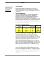
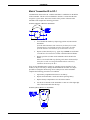
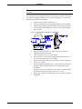
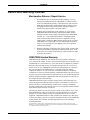
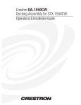
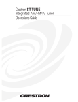
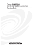
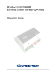
CRESTRON Contents SmartPresenter™: SP-1 1 Scope ................................................................................................................................... 1 Overview ............................................................................................................................. 1 Description .......................................................................................................................... 2 System Description................................................................................................. 2 Functional Description of the SmartPresenter ......................................................... 3 Physical Description of the SmartPresenter............................................................. 4 Leading Specifications ......................................................................................................... 7 Setup.................................................................................................................................... 8 SPS Equipment ...................................................................................................... 8 Hardware Hookup................................................................................................... 8 Match Transmitter ID to SP-1 .............................................................................. 10 Q-Codes ............................................................................................................... 11 IR Sprayer Usage.................................................................................................. 12 Macro Setup – Linking a Device........................................................................... 13 Controlling a PC (Mouse and/or Keyboard) .......................................................... 15 Controlling a RS-232 Projector or Switcher.......................................................... 15 Controlling a Fifth (Non-IR) Device..................................................................... 16 Problem Solving................................................................................................................. 17 Troubleshooting ................................................................................................... 17 Further Inquiries .................................................................................................. 17 Return and Warranty Policies............................................................................................. 18 Merchandise Returns / Repair Service .................................................................. 18 CRESTRON Limited Warranty ............................................................................ 18 Operations Guide - DOC. 5712 Contents • i CRESTRON SmartPresenter™: SP-1 Scope The intent of this Operations Guide is two-fold. First, it is meant as a comprehensive reference for the SmartPresenter™ system (SPS or SPSL). This document provides a system description, a list of system and ancillary equipment, system setup details, and advanced features that require use of SmartPresenter software. A less detailed presentation is available in the latest revision of the Quick Guide (Doc. 5742). The Quick Guide offers a follow-by-example approach to the SmartPresenter. Second, this guide serves as the specific reference for the SP-1, the RF control center and receiver ( also known as “the Box”) which is one of four components of the SPS. The other three major components have their own documentation and their system functionality is mentioned in “System Description” on page 2. Overview The SmartPresenter™ is a complete, professional, compact control system that integrates computer and A/V presentation technology with the touch of a button. Setup is easy and requires no PC programming or software. SPS offers convenient fingertip control of your PC keyboard and mouse, projector, VCR, slide projector and more! SmartPresenter sets up in minutes, perfect for the training room, conference room, or auditorium. Setup is similar to that of a universal remote - just choose your devices from our extensive database and go! This is one powerful little professional, presentation system. No product available today rivals SmartPresenter's power and performance. The RF remote is a perfect match for any room, eliminating the line-of-sight problems encountered with infrared (IR) remotes. A 500 foot range provides mobility to the presenter so that anyone can concentrate on the presentation and not the remote. SmartPresenter is also the only control system built for people on the go. Just pack the SmartPresenter with a laptop to obtain whole room control, anywhere needed. No need to juggle multiple remotes or walk back and forth to the laptop or projector. SmartPresenter puts the whole room at the presenter’s fingertips. SmartPresenter is affordable for any presentation situation. Whether the need is permanent control for a training room, conference room, or auditorium - or portable control for rentals and presenters on the go – SmartPresenter is the easiest way to a better presentation. Operations Guide - DOC. 5712 SmartPresenter™: SP-1 • 1 CRESTRON Description System Description The SPS system is comprised primarily of a hand-held RF user interface (transmitter), SP-1 (which serves as the RF control center and receiver), an IR sprayer (SP-MB), and programming cable (SP-CBL, used for advanced features). The SPS offers full PC mouse and keyboard control as well as control for up to four audio/video (A/V) devices such as video projectors and VCRs. There is also an output port for controlling one RS-232-type device. As an out-of-the-box control system in both the rental and integrated system markets, SPS has been specifically designed so that minimal setup is required on site. No software or PC is required for the basic setup. Refer to the illustration below for an out-of-the-box application example. The illustration demonstrates that the transmitter (CNWM) provides commands via RF to the SP-1. The SP-1 in turns processes the signals to generate commands to a number of possible controlled devices as well as control of PC keyboard functions. Other arrangements are conceivable with additional parts, sold separately. Refer to “Hardware Hookup” on page 8 for suggestions. SmartPresenter System 2 • SmartPresenter™: SP-1 Operations Guide - DOC. 5712 CRESTRON The most recent version of the SmartPresenter software can be obtained from the Downloads page of the Crestron FTP site (www.crestron.com). System Software A Windows-based software package, SmartPresenter, is available but only necessary when performing the more advanced features of this system (i.e., configuration cloning, adding devices to the User Database, controlling a fifth device, or upgrading firmware). The software also offers the option to print a list of supported devices. System Configurations There are six SPS systems available, refer to table after this paragraph. Each configuration is identical with respect to the four basic components: SP-1, transmitter, sprayer, and cable. The configurations differ due to the frequency requirements in certain parts of the world, the power pack specification requirements of the SP-1, and whether the laser pointer transmitter is used. Systems that operate at 418 MHz are denoted with the “/UK” suffix. Systems that operate at 433.92 MHz do not have the suffix. An “I” after the second “S” in SPS or the “/UK” suffix indicates the need for a 220V external power pack. If the “I” and “/UK” suffix are omitted, a 110V power pack is required. The “-L” suffix indicates the system utilizes a laser pointer transmitter. Major Components of the SmartPresenter System SMARTPRESENTER POWER PACK SMARTPRESENTER TRANSMITTER SYSTEM (VOLTAGE) SPS SPSI SPS-L SPSI-L SPS/UK SPS-L/UK SP-1 SPI-1 SP-1 SPI-1 SP-1/UK SP-1/UK 110V 220V 110V 220V 220V 220V CNWM CNWM CNWML CNWML CNWM/UK CNWML/UK Functional Description of the SmartPresenter The SP-1 has been designed to remain in the room with all of the controlled devices. The unit has all the ports necessary to output IR and RS-232 commands to controlled devices. IR probes (sold separately) can be affixed to each device or an IR sprayer (attached to a designated SP-1 output) can be positioned to “spray” IR signals to all controllable devices in the room. The SP-1 contains a Crestron Database of supported device codes (Q-Codes). QCodes are the six-digit codes assigned to each model-specific device in the Crestron Database. These codes are similar to those implemented with universal remotes for home use. Each digit in the code corresponds to one of four characters (1, 2, 3, or 4). There is a unique Q-Code for each device in the Crestron Database. If the QCode does not exist, it can be added to the User Database via the SmartPresenter software. Refer to “Adding Q-Codes” on page 11. The SP-1 accepts RF signals from the transmitter which has numbered buttons (known as device control buttons, labeled 1 through 4). These buttons correspond to the numbered IR output ports on the SP-1. Once a device is assigned to an output, selecting a device with a numbered device control button readies that device for any subsequent function commands that may be sent. The selected device remains active until another device is selected via the numbered device control buttons on the transmitter. Operations Guide - DOC. 5712 SmartPresenter™: SP-1 • 3 CRESTRON Physical Description of the SmartPresenter There are three SmartPresenters available: SP-1, SPI-1, and SP-1/UK. Configuration differences depend on the input power requirements and the communication frequency. The SP-1 requires a 110V external AC power pack and operates at 433.92 MHz. The SPI-1 requires a 220V external AC power pack and operates at 433.92 MHz. The SPI-1/UK requires a 220V external AC power pack and operates at 418 MHz. This configuration is required for operation in the United Kingdom and alike. For purposes of this Operations Guide, the term SP-1 is used interchangeably for both configurations, except where noted. The SP-1, shown after this paragraph, is housed in a black enclosure with silkscreened labels on the front and rear panels. On the front of the unit there are six LEDs for indicating the unit’s current status and four buttons for programming the SP-1 with proper device codes. All the connections, except for the antenna and its right angle adapter, are made on the back of the unit. Refer to the physical views shown below. There are four rubber feet on the base of the unit for stability and to prevent slippage. SP-1 Physical Views 4 • SmartPresenter™: SP-1 Operations Guide - DOC. 5712 CRESTRON SP-1 Ports A number of ports are provided on the back of the SP-1. Each has a silk-screened label. Refer to the illustration and descriptions below. SP-1 Ports 12 VDC .5 A (Power) This DC power socket connector is used to supply power via the Crestron external 12VDC 500 mA power pack, Crestron P/N PW-1205 or equivalent (1000 mA power pack for the SPI-1 and SP-1/UK configurations, Crestron P/N PWI-1210 or equivalent). If an external AC power pack other than the Crestron model is obtained, verify that it meets the required specifications and polarity as shown in the table and illustration after this paragraph. AC Power Pack Specifications CRESTRON POWER PACK INPUT SPECS OUTPUT SPECS PW-1205 PWI-1210 120V 60Hz 230V~50Hz 12VDC 500mA 12VDC 1000mA AC Power Pack Polarity PC (Computer/RS-232) This 6-pin, 6-position RJ11 modular RS-232 jack is used for driver downloading, system configuration, and transferring commands to an RS-232 device. The pinout for the connector is shown after this paragraph. NOTE: The maximum baud rate supported for device control is 38400 bps. RJ11 Pinout PIN DESCRIPTION 1 2 3 4 5 6 CTS GND RXD TXD RTS No Connection MOUSE IN This PS/2 connector connects to any PS/2-style mouse; offers optional pass-through capability. Operations Guide - DOC. 5712 SmartPresenter™: SP-1 • 5 CRESTRON MOUSE OUT NOTE: One SmartPresenter cable, SP-CBL, for use with either a keyboard or mouse, is supplied with the SmartPresenter system. This PS/2 connector connects to the mouse port on the PC via the supplied cable, SP-CBL. Make this connection only if PC is to be controlled. KEYBOARD IN This PS/2 connector connects to any PS/2-styled keyboard; offers optional passthrough capability. KEYBOARD OUT NOTE: One SmartPresenter cable, SP-CBL, for use with either a keyboard or mouse, is supplied with the SmartPresenter system. This PS/2 connector connects to the keyboard port on the PC via the supplied cable, SP-CBL. Make this connection only if PC is to be controlled. OUTPUT (1 - 4) These 3.5mm mini phone jacks are used to control IR devices via the IR sprayer (SP-MB, supplied and must be connected to output #1 only) or an IR probe (STIRP, sold separately), slide projector via the Crestron slide controller (SP-SC, sold separately), or miscellaneous devices through relays (SP-RY, sold separately). A macro feature to “link” the function of a device (such as a video projector or switcher) assigned to SP-1 output #4 is available. Refer to “Macro Setup – Linking a Device” on page 13 for details. ANTENNA This 50 ohm BNC connector attaches to the supplied antenna which is used to retrieve RF signals from the transmitter. Use the supplied female/male right angle adapter if there is not enough room to attach the antenna directly. In some installations, the RF reception range can be increased by mounting the antenna away from the equipment with a BNC male to BNC male 50 ohm cable and barrel adapter (purchased separately). SP-1 Indicators There are six LED indicators located on the front panel of the SP-1. Refer to the illustration and descriptions following this paragraph. SP-1 Receiver Indicators PWR (Power) This LED illuminates when 12 volts (from an external AC power pack) is supplied to the SP-1. 6 • SmartPresenter™: SP-1 Operations Guide - DOC. 5712 CRESTRON RF This LED illuminates when the SP-1 receives RF transmissions from a transmitter (CNWM or CNMWL) with a matching RF ID. Refer to “Match Transmitter ID to SP-1” on page 10 for details. OUTPUT (1 - 4) These LEDs illuminate or blink for a number of reasons: to indicate which output device is selected, during RF diagnostics, during device setup and verification, and while verifying routing. Leading Specifications The table below provides a summary of leading specifications for the SP-1. Dimensions and weight are approximations rounded to the nearest hundredth unit. Leading Specifications of the SP-1 SPECIFICATION Required External AC Power Pack: Domestic AC adapter International AC adapter SmartPresenter(TM) Software Crestron Database Dimensions Weight (without antenna) DETAILS 12V DC, 0.5A, 120V Input (P/N PW-1205) 12V DC, 1.0A, 230V Input (P/N PWI-1210) Version 1.0 or later Version 11.7.208 or later Height: 1.78 in (4.53 cm) Width: 7.07 in (17.95 cm) Depth: 6.32 in (16.06 cm) Weight: 1.96 lb (0.89 kg) As of the date of manufacture, the unit has been tested and found to comply with specifications for CE marking. NOTE: This equipment has been tested and found to comply with the limits for a Class B digital device, pursuant to part 15 of the FCC Rules. These limits are designed to provide reasonable protection against harmful interference in a residential installation. The equipment generates, uses and can radiate radio frequency energy and, if not installed and used in accordance with the instructions, may cause harmful interference to radio communications. However, there is no guarantee that interference will not occur in a particular installation. If this equipment does cause harmful interference to radio or television reception, which can determined by turning the equipment off and on, the user is encouraged to try to correct the interference by one or more of the following measures: Operations Guide - DOC. 5712 n Reorient or relocate the receiving antenna. n Increase the separation between the equipment and receiver. n Connect the equipment into an outlet on a circuit different from that to which the receiver is connected. n Consult the dealer or an experienced radio/TV technician for help. SmartPresenter™: SP-1 • 7 CRESTRON Setup SPS Equipment Due to variations in installation requirements and overall application, not all possible peripheral pieces of equipment are supplied with the SPS system. The table below provides a list of equipment that can be used within the SPS system. SPS Equipment EQUIPMENT Transmitter Receiver/Control Processor Communication Cable Infrared Sprayer Software Carrying Case External AC Power Pack Individual Infrared Probe PC Port Cable PC Port Cable PC Port Cable PC Port Cable IR/Serial Port Cable IR/Serial Port Cable Relay Controller Slide Controller PART NUMBER SHIPPED WITH CNWM, CNWML, CNWM/UK, CNWML/UK SP-1, SPI-1, SP-1/UK All SPS Configurations* All SPS Configurations* All SPS Configurations* All SPS Configurations* Note 1 Wireless mouse provides user interface. sold separately SP-CBL SP-MB Not Applicable SP-CASE PW-1205 (domestic), PWI-1210 (international) STIRP DESCRIPTION Accepts RF commands from the wireless mouse and provides IR commands to controlled equipment. Allows the SmartPresenter system to communicate with a PC through the keyboard or mouse port. IR sprayer controls multiple IR devices by "spraying" the defined area with IR signals. Allows new driver files to be retrieved and added to the database residing in the SP-1. sold separately Contains pre-cut foam that offers provisions for the SmartPresenter system hardware and accessories. SP-1, SPI-1, SP-1/UK Power pack supplies power to receiver (12 VDC). SPC-121 SPC-122 SPC-124 SPC-550 ST-112 sold separately sold separately sold separately sold separately sold separately Infrared emitter that provides IR control signals sent by the receiver. Cable required to control RS-232 switcher devices. Cable required to control RS-232 switcher devices. Cable required to control RS-232 switcher devices. Cable required to control RS-232 switcher devices. Cable required to control IR/serial devices. ST-109 sold separately Cable required to control IR/serial devices. SP-RY SP-SC sold separately sold separately Controls devices with low voltage contact closures. Designed to interface with a Kodak slide projector. * This includes SPS, SPSI, SPS-L, SPSI-L, SPS/UK, and SPS-L/UK. NOTE 1: The latest version of SmartPresenter software is available from the Crestron website (www.crestron.com). Hardware Hookup NOTE: The SmartPresenter has been designed to work with a large variety of devices (i.e., PCs, VCRs, projectors, etc.). Crestron recommends that the user verifies the control functionality of devices with the SmartPresenter prior to making a presentation. Should any anomalies arise, contact the Crestron SmartPresenter help desk, refer to “Further Inquiries” on page 17. The SmartPresenter has been designed as an out-of-the-box solution for many control applications in both the rental and integrated system markets. Minimal 8 • SmartPresenter™: SP-1 Operations Guide - DOC. 5712 CRESTRON hardware setup is required. Due to the multiple applications, an overall hookup diagram is presented after this paragraph. Not every connection is required. Complete the following hardware hookup procedure in the order presented. Possible Hookup Connections for the SP-1 1. Attach antenna to SP-1 using right angle adapter. 2. Disconnect power to the PC (only if PC mouse/keyboard is used). 3. Attach all necessary PC cables to PC and SP-1 (only if PC mouse/keyboard is used). 4. Connect power (model PW-1205, PWI-1210, or equivalent) to SP-1 input power jack (labeled as 12VDC .5A). 5. Plug power pack into active outlet. One or more of the feedback options occur, then observe that the green PWR LED turns on. 6. Operations Guide - DOC. 5712 • All LEDs (1 through 4) flashing simultaneously, three times, indicates there is an invalid setting for one of the devices. Refer to “Q-Code Assignment Error” on page 12 for details. • LEDs 1 and 2 flash to indicate that that a valid mouse driver is installed and a mouse is properly connected to the MOUSE IN port. • LEDs 3 and 4 flash to indicate that that a valid keyboard driver is installed and a keyboard is properly connected to the KEYBOARD IN port. • LEDs illuminate in a reverse sequence (4-3-2-1) to indicate SP-1 is ready to use. Apply power to the PC (only if PC mouse/keyboard is used). SmartPresenter™: SP-1 • 9 CRESTRON Match Transmitter ID to SP-1 Communication between the SP-1 and the transmitter is established via the RF ID of the transmitter. This ID can be transmitted to the SP-1 to ensure that the SP-1 recognizes a given mouse. Notice the location of the position A button on the transmitter and complete the following procedure. Location of Position A Button on Transmitter 1. Test if the RF ID matches by depressing (position A) button on the transmitter. If the RF LED illuminates and remains on for about four seconds, communication is verified and no further steps need to be taken. If the RF LED does not illuminate, proceed with the next step. 2. Depress (with a blunt object e.g., paper clip) and hold recessed button #1 on the SP-1 for at least five seconds or until the RF LED flashes. 3. Depress (position A) button on the transmitter while the RF LED flashes. Observe that the RF LED stops flashing and remains illuminated for about four seconds. An extinguished LED indicates a match of transmitter ID to that of the SP-1 If two or more SmartPresenter systems are operating in close proximity of one another, it may be necessary to change the transmitter RF ID. There is a simple procedure to change the RF ID using device button presses on the transmitter. Complete the following procedure to set an RF ID. 1. Open battery compartment and remove one battery. 2. Depress and hold button 1 on the unit while replacing battery. 3. Replace battery compartment cover and release button 1. 4. Use the device buttons on the transmitter to enter one of the eight-digit codes found in the table after this step. Location of Device Button 1 on Transmitter 10 • SmartPresenter™: SP-1 Operations Guide - DOC. 5712 CRESTRON Possible RF ID Alternatives The most recent version of the SmartPresenter software can be obtained from the Downloads page of the Crestron FTP site (www.crestron.com). RF ID 8-DIGIT CODE 0A 1A 2A 3A 4A 5A 6A 7A 8A 9A AA BA CA DA EA FA 22224242 22244242 22424242 22444242 24224242 24244242 24424242 24444242 42224242 42244242 42424242 42444242 44224242 44244242 44424242 44444242 Q-Codes The most current and complete set of Q-Codes (Crestron Database) is always available from the latest version of SmartPresenter software. The SmartPresenter Quick Guide (Doc. 5742) lists a set of Crestron Q-Codes. The Q-Code list is arranged alphabetically and broken down by device category, manufacturer, and model number. The Crestron Database of controllable devices is updated periodically. Newer QCode printouts should be obtained. The software allows for the printing of the entire list or a partial list (defined by device category and/or manufacturer). Consult the help file that accompanies the SmartPresenter software for details. Search on “Print Database”. Adding Q-Codes Implementing features of the User Database is an advanced feature of the SmartPresenter which requires the software. Aside from the Q-Codes supplied in the Crestron Database, a User Database can be created via the SmartPresenter software. A range of Q-Codes (441111 through 444443) has been set aside for assigning additional Q-Codes to the User Database. Consult the help file that accompanies the SmartPresenter software for details or contact a Crestron technical representative (refer to “Further Inquiries” on page 17). Q-Code Assignment In order to control a device with the SmartPresenter system, a valid Q-Code for the device must be assigned to an SP-1 output. Assignment is achieved by activating an SP-1 output and then transmitting the valid Q-Code with the transmitter. Assignments can be verified. Complete the following procedures on the next page for each operation. Operations Guide - DOC. 5712 SmartPresenter™: SP-1 • 11 CRESTRON Assignment The most recent version of the SmartPresenter software can be obtained from the Downloads page of the Crestron FTP site (www.crestron.com). 1. Depress (with a blunt object e.g., paper clip) recessed button on SP-1 that is associated with a particular device output. Observe that the red device output LED associated with the output flashes. 2. Use the device buttons (numbered 1 through 4) on the transmitter to enter the desired six digit Q-Code. The entire Q-Code list is available from the latest revision of the SmartPresenter Quick Guide (Doc. 5742). After six digits have been entered, the SP-1 responds by flashing the Q-Code in the entered sequence. 3. Repeat steps 1 and 2 for the remaining device outputs, if applicable. NOTE: Entering Q-Code (111111) disables the output. Verification Depress (with a blunt object e.g., paper clip) associated recessed button on SP-1 for a given device output twice. Observe that the red device output LED associated with the output flashes after the first button press. The SP-1 responds by flashing the Q-Code sequence for the given output, after the second button press. Q-Code Assignment Error When a device output on the SP-1 has been assigned an invalid Q-Code, all red device output LEDs (1, 2, 3, and 4) on the SP-1 flash three times. The error signal can occur during one of the following situations. • Q-Code assignment • Q-Code verification • Saving routed settings (Refer to “IR Sprayer Usage” on page 12) • Upon power up (Refer to “Hardware Hookup” on page 8 for procedure) When an error signal appears upon power up, verify the Q-Code for each output. Upon finding a code that is invalid, reassign the Q-Code per “Adding Q-Codes” on page 11. IR Sprayer Usage Each SmartPresenter system contains one IR sprayer (SP-MB). The SP-MB is designed to control multiple IR devices by “spraying” a defined area with IR signals. This feature of the SmartPresenter system eliminates the need to attach an IR probe to each device. To function properly, the SP-MB must be plugged into OUTPUT 1 on the SP-1. The sprayer end of the SP-MB must be placed within six feet or less of the devices being controlled. IR signals are delivered within a 120° angular cone of radiation. To selectively route some of the IR signals output from the SP-1, the SP-1 must be placed into “edit mode”. Once in this mode, it is possible to toggle the routing of 12 • SmartPresenter™: SP-1 Operations Guide - DOC. 5712 CRESTRON each output. The final step of the procedure is to save the routing settings. Complete the following procedure to selectively route IR commands to the SP-1 outputs. 1. Depress (with a blunt object e.g., paper clip) the recessed button (labeled 1) on the SP-1. Observe flashing red device output #1 LED. 2. Depress the recessed button (labeled 2) on the SP-1. Observe which device output LEDs flash red. A flashing LED indicates that IR signals intended for the associated outputs are routed to output #1 on the SP-1. The SP-1 is now in “edit mode”. 3. Toggle SP-1 recessed button (numbered 2, 3, or 4) to edit routing of IR commands from a particular output. Observe that the device output LED associated with the formally routed output no longer flashes when toggled. Likewise, observe that the device output LED associated with the device that was not routed flashes when toggled. 4. Repeat step 3 as necessary. 5. Depress the recessed button (labeled 1) on the SP-1 to save routed settings. NOTE: To route the IR signals for all device outputs to OUTPUT 1 on the SP-1, reapply power to the SP-1 while depressing (with a blunt object e.g., paper clip) the recessed button (labeled 1) on the SP-1. Release button after LED #1 illuminates and remains on. NOTE: To completely disable routing (i.e., IR signals are only output from their respective SP-1 output), reapply power to the SP-1 while depressing (with a blunt object e.g., paper clip) the recessed button (labeled 2) on the SP-1. Release button after LED #2 illuminates and remains on. Macro Setup – Linking a Device The macro capability of the SP-1 allows the “linking” of a controlled function (assigned to device 4) to the device selection by simply pressing a device button (1 through 3) on the transmitter. Device Control Buttons (1 Through 4) on Transmitter Operations Guide - DOC. 5712 SmartPresenter™: SP-1 • 13 CRESTRON NOTE: Crestron recommends that the “linked” device be either a video projector or switcher. For example, if a VCR (assigned to button 1) is required to select the Video1 input on a projector (assigned to button 4), it is necessary to link device 1 to device 4 to make the macro function automatically. 1. Assign a valid Q-Code to output device 4. 2. Verify by selecting device 4 and pressing the device control buttons, until the correct image is displayed. Make a notation for each device needed to link. The information is required to successfully complete this procedure. Device Control Buttons (A Through F) on Transmitter 14 • SmartPresenter™: SP-1 3. Depress (with a blunt object e.g., paper clip) the recessed device assignment button 4 on the SP-1. Observe flashing red device output #4 LED. 4. Depress the SP-1 recessed device assignment button (numbered 1, 2, or 3) associated with a device to be “linked”. Observe two flashing red device output LEDs (4 and the LED for the device to be “linked”). 5. Per the information gathered in step 2, select a function for the device assigned to output 4 by depressing a device control button on the transmitter. Observe that the two flashing device output LEDs extinguish and the red RF LED illuminates for approximately five seconds. 6. Repeat steps 3 through 5 for the other two device outputs on the SP-1, if applicable. Operations Guide - DOC. 5712 CRESTRON Controlling a PC (Mouse and/or Keyboard) The mouse and/or keyboard of a PC can be controlled via the SP-1 ports labeled MOUSE OUT and KEYBOARD OUT, respectively (refer to the illustration after this paragraph). Assign the appropriate Q-Code as defined in “Q-Code Assignment” on page 11 (i.e., the Q-Code to control all MS compatible mice is 111133). For other mice or keyboard Q-Codes, refer to the Crestron Q-Code list in the latest revision of the SmartPresenter Quick Guide (Doc. 5742). Hookup Connection for Controlling a PC TO KEYBOARD PORT ON PC TO MOUSE PORT ON PC NOTE: Some laptops only have a single mouse/keyboard port. In such an event, choose to control either the mouse or the keyboard. Controlling a RS-232 Projector or Switcher A RS-232 projector or switcher can be controlled with the SmartPresenter only if the the Q-Code is assigned to OUTPUT 4 on the SP-1. The SP-1 recognizes the QCode as an RS-232 switching device and outputs commands for that device to the PC port (rather than the OUTPUT 4 port). SmartPresenter cables (not supplied) are required to connect the SP-1 to the switching device (refer to illustration below). These cables are listed in the “SPS Cable Index” found in the latest version of the SmartPresenter Quick Guide (Doc. 5742). For example, assign an Extron MX Series switcher (Q-Code 124132) to OUTPUT 4. Use SPS-121 PC port cable to connect the switcher to the SP-1. Hookup Connection for Controlling a RS-232 Projector or Switcher RS-232 SWITCHER OR PROJECTOR SMARTPRESENTER CABLE Operations Guide - DOC. 5712 SmartPresenter™: SP-1 • 15 CRESTRON Controlling a Fifth (Non-IR) Device Controlling a fifth (non-IR device is an advanced feature of the SmartPresenter which requires the Windows-based SmartPresenter software. A fifth device can be controlled via the SP-1 port labeled PC (refer to the illustration below). Crestron recommends that the fifth device communicate via RS-232 and either be a switcher or video projector. The Q-Code for the device is assigned via the SmartPresenter software, refer to the SmartPresenter software help file for details. Search on “Switching Device”. Hookup Connection for Controlling a Fifth (non-IR) Device TO RS-232 DEVICE (SWITCHER OR VIDEO PROJECTOR) 16 • SmartPresenter™: SP-1 Operations Guide - DOC. 5712 CRESTRON Problem Solving Troubleshooting The table that follows this paragraph provides corrective action for possible trouble situations. If further assistance is required, please contact a Crestron technical support representative. SP-1 Troubleshooting TROUBLE POSSIBLE CAUSE(S) CORRECTIVE ACTION Intermittent device response during transmission. Batteries in transmitter Install new batteries. are weak. SP-1 has been moved. Verify that the distance between SP-1 and transmitter is not more than 200 feet. SP-1 is in vicinity of Verify that a large amount of metal is not metal. blocking transmission. Refer to corrective actions for intermittent Refer to causes for IR response during transmission. controllable intermittent response device does during transmission. not respond. Batteries in transmitter Install new batteries. are missing or dead. External power pack of Verify that external power pack is properly SP-1 is unplugged. attached to SP-1 and the SP-1 is receiving power. RF ID of transmitter is Refer to "Match Transmitter ID to SP-1" in not recognized by SP-1. this Operations Guide. SP-MB is not properly Refer to "IR Sprayer Useage" in this placed. Operations Guide. IR probes are not Verify placement of STIRP over IR window of properly placed. controlled device and that the 3.5 mm connector is properly inserted into the correct SP-1 output port. Incorrect Q-Code has Refer to the subsection "Q-Code Assignment" under "Q-Codes" in this been assigned for a Operations Guide. given device. Further Inquiries If after reviewing this Operations Guide for the SP-1, you cannot locate specific information or have questions, please take advantage of Crestron's award winning technical support team by calling: • In the US and Canada, call Crestron’s corporate headquarters at 1-888-CRESTRON [1-888-273-7876] or 1-201-767-3400. • In Europe, call Crestron International at +32-15-50-99-50. • In Asia, call Crestron Asia at +852-2341-2016. • In Latin America, call Crestron Latin America at +525-574-15-90. For local support from exclusive Crestron factory-trained personnel call: Operations Guide - DOC. 5712 • In Australia, call Soundcorp at +613-941-61066. • In New Zealand, call Amber Technologies at +649-410-8382. SmartPresenter™: SP-1 • 17 CRESTRON Return and Warranty Policies Merchandise Returns / Repair Service 1. No merchandise may be returned for credit, exchange, or service without prior authorization from CRESTRON. To obtain warranty service for CRESTRON products, contact the factory and request an RMA (Return Merchandise Authorization) number. Enclose a note specifying the nature of the problem, name and phone number of contact person, RMA number, and return address. 2. Products may be returned for credit, exchange, or service with a CRESTRON Return Merchandise Authorization (RMA) number. Authorized returns must be shipped freight prepaid to CRESTRON, Cresskill, N.J., or its authorized subsidiaries, with RMA number clearly marked on the outside of all cartons. Shipments arriving freight collect or without an RMA number shall be subject to refusal. CRESTRON reserves the right in its sole and absolute discretion to charge a 15% restocking fee, plus shipping costs, on any products returned with an RMA. 3. Return freight charges following repair of items under warranty shall be paid by CRESTRON, shipping by standard ground carrier. In the event repairs are found to be non-warranty, return freight costs shall be paid by the purchaser. CRESTRON Limited Warranty CRESTRON ELECTRONICS, Inc. warrants its Cresnet products, denoted by a "CN" prefix model number, to be free from manufacturing defects in materials and workmanship for a period of three (3) years from the date of shipment to purchaser. Disk drives and any other moving or rotating mechanical parts are covered for a period of one (1) year. CRESTRON warrants all its other products for a period of one year from the defects mentioned above, excluding touchscreen display components which are covered for 90 days. Incandescent lamps are completely excluded from Crestron's Limited Warranty. CRESTRON shall, at its option, repair or replace any product found defective without charge for parts or labor. Repaired or replaced equipment and parts supplied under this warranty shall be covered only by the unexpired portion of the warranty. CRESTRON shall not be liable to honor warranty terms if the product has been used in any application other than that for which it was intended, or if it has been subjected to misuse, accidental damage, modification, or improper installation procedures. Furthermore, this warranty does not cover any product that has had the serial number altered, defaced, or removed. This warranty shall be the sole and exclusive remedy to the purchaser. In no event shall CRESTRON be liable for incidental or consequential damages of any kind (property or economic damages inclusive) arising from the sale or use of this equipment. CRESTRON makes no other warranties nor authorizes any other party to offer any warranty, expressed or implied, including warranties of merchantability for this product. This warranty statement supersedes all previous warranties. Trademark Information All brand names, product names, and trademarks are the sole property of their respective owners. Windows is a registered trademark of Microsoft Corporation. Windows95, Windows98 and WindowsNT are trademarks of Microsoft Corporation. 18 • SmartPresenter™: SP-1 Operations Guide - DOC. 5712