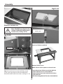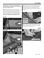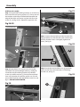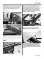
1
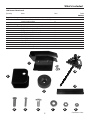
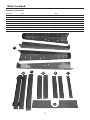
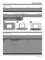
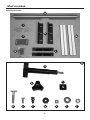
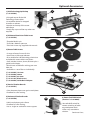
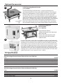
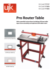
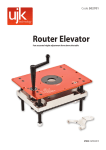
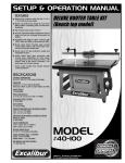
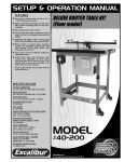
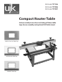
Kit Code 717126 Kit Code 717206 Kit Code 717207 Compact Router Table Hole assembly instructions including all three table tops, fence assembly and optional UJK table insert UJK Pro Cast Iron Table Top UJK Phenolic Table Top UJK MDF Table Top Index of Contents Index of Contents 02 Introduction02 What’s Included 03-04-05-06 UJK Router Table Stand UJK Router Table Tops UJK Fence Assembly Optional Accessories 7-8 Kit Specifications 08-09 General Instructions for 230V Machines 09 General Safety Instructions 10 Assembly11-19 UJK Router Table Stand Assembly 11-12 Router Table Top Assembly 13-14 Optional Table Inserts 14-15 UJK Fence Assembly 16-17-18-19 Mitre Fence Assembly 19 Tool Storage Holders 19 Overview Description 20-21 Mounting the Router 22-23 Operating Instructions 24 Parts Drawing/List (Router Table & Stand Assembly (E Type) 25-26 Parts Drawing/List (Router Table Fence Assembly) 27-28 Notes 29-30-31 Introduction The UJK Technology Compact Leg Stand with splayed legs is of sturdy construction, very stable and of a size that offers portability around the workshop or on site. Provision is made for storage of the supplied mitre fence assembly. Measuring 370mm high, with a footprint of 580 x 390mm, this leg stand is such a useful size and could also be used for mounting many other small machines. The fence is a superb quality single aluminium section supplied with a transparent dust port for efficient extraction from above the table. Provision is made for the fitting of guards and accessories with a T-slot at both the top and front of the fence. The Phenolic or MDF Router Table Tops are additional options that you can choose from when making up your UJK router table. Phenolic resin is a very stable material and may be a good choice if your workshop suffers from damp or humid conditions. The MDF Router Table Top is a very sturdy versatile unit capable of many routing operations. An extruded aluminium track is provided which includes a standard 19mm track for the use of a mitre fence and a T-track slot is also provided for other jigs and accessories. Adjustable scales are provided for attachment at either side of the table and the fence is attached to these and locks into place at the required position. A scale is also provided for the top of the fence with the zero position at the centre. Adjustable in-feed and out-feed fences attach to either side of the aluminium section and the central aperture can be opened and closed according to the diameter of the cutter in use. Fence measures 904 x 90mm high. Warning Fully read manual and safety instructions before use An adjustable transparent guard is included for your safety. The symbols below advise that you follow the correct safety procedures when using this tool. Ear protection should be worn Eye protection should be worn 2 Dust mask should be worn What’s Included UJK Router Table Stand Quantity Item Part Bag 1 Containing: 1 No Mitre Fence Bracket Holder with two Phillips screws and washers 1 Bag 2 Containing: 1 No 4 No 4 No 2 No 34 No 38 No 38 No 2 No 1 No 1 No Code 502533 2 3 4 5 6 7 8 9 10 Tool Bracket (with two pre-drilled holes) Rubber Feet Phillips Screws (M6x20mm) Phillips Screws (M4x20mm) Coach Bolts (M6x12mm) Flat Washers (M6) Nuts (M6) Nuts (M4) Mitre Fence Mitre Fence Extension (with two Butterfly nuts and washers) 11 1 10 2 11 3 4 5 6 7 3 8 9 Continues Over... What’s Included UJK Router Table Stand Quantity Item Part 4 No 2 No 1 No 2 No 2 No 1 No 1 No Leg Supports Brackets Front and Back Upper Panels Front Lower Panel Side Lower Panels Side Upper Panels Side Centre Panel Rear Extractor Panels A B C D E F G A B C D E G 4 F What’s Included UJK Router Table Tops Quantity Item Part 1 No UJK Compact Cast Iron router table top A 1 No UJK Compact Phenolic router table top B 1 No UJK Compact MDF router table top C Code 502532-502746 Bag Containing 10 No 10 No 10 No 10 No 10 No Bag Containing 10 No 6 No Countersink Phillips Screws (M6x20mm) M6 Nuts Hex Bolts (M6x12mm) M6 Washers Spring Washers A B UJK Pro Cast Iron Table Top Code 502532 502746 502744 Code 502744 Countersink Phillips Wood Screws Phillips Head Wood Screws C UJK Phenolic Table Top UJK MDF Table Top UJK Fence Assembly Quantity Item Part 1 No Fence H 1 No Extraction Moulding I 1 No Dust Shield J 2 No Fence Fixing Brackets with Scale K 2 No Fence Fixing Brackets L 2 No Adjustable Wood Faces M 1 No 2 No 8 No 2 No 8 No 6 No 6 No 2 No 6 No 10 No 6 No Bag Containing Locking Handle Knob (5/16”) M8 Locking Knobs Fence Spacers ‘T’ Bolts (M8x43mm) Hex Screws (M6x12mm) Hex Bolts (1/4”) (with flat & spring washers) Lock Hex Nuts (5/16”) Square Nuts (1/4” ) M8 Flat Washers M6 Flat Washers 5 Code 502534 N a b c d e f g h i j Continues Over... What’s Included UJK Fence Assembly H I K M J N L N a c b d e f g 6 h i j Optional Accessories 2 1 1) UJK Technology QuickStop (Code 502569) •A hinged stop to fit the UJK Technology router tables. •An excellent device for stopped chamfers or rebates. •Attaches to the top of the router table fence. •Simply flips up out of the way when not required. 2) UJK 6mm Aluminium Table Insert (Code 502749) 502566 502567 • Threaded lead-in pin. • To fit 230 x 306mm aperture. • Twist lock insert ring supplied with wrench. 3 3) Router Table Inserts • A range of central inserts for the • Axminster or UJK router elevator • Also suitable for UJK Technology aluminium and phenolic router table insert plates. • Sizes include 12.6mm, 38mm, 63.4mm plus a guide bush adaptor. • Blank insert available for making your own hole size. • Available as a set of four or individually. 502565 502525 951187 (Code 502565) 12.6mm (Code 502566) 38mm (Code 502567) 63.4mm (Code 951187) Blank Insert (Code 502525) Guide Bush Adaptor 4 4) Vertical Feather Boards (Code 502751) • Gives downward pressure against workpiece. • Excellent for safer routing. 5) Horizontal Feather Boards (Code 502750) 5 6 • Holds work piece against fence. • Excellent for safer routing. • Use as singles or stacked for more support. 7 6) Power Tool NVR Switch (Product Code 910065) •Versatile NVR switch for remote switching of table mounted power tools. •Offers very convenient solution. Continues Over... Optional Accessories 7 7) UJK Technology Router Elevator (Code 502701) The UJK Technology router elevator is a logical solution for fast, accurate production on many router table installations. This compact design was developed by us to fit straight into our own router tables and most table set-ups can accommodate this size of insert (305 x 229 x 6mm). The unit can be made to fit flush into the tabletop by the provision of levelling screws at each corner of the table insert. Height adjustment is carried out by inserting a handle through a measurement dial set into the machine table. Each rotation of the handle raises or lowers the cutter by exactly 2mm and the integral scale is graduated into increments enabling very accurate adjustments to be carried out. 8) UJK Technology Dust Extraction Box (Code 502538) 8 • Dust collection device. • Efficient extraction from above and below the table. •Access door with magnetic catch. •63mm extraction hose included. •100mm outlet. Dust extraction from a router table can be difficult and for it to work effectively it needs to extract from both above and below the table. Designed to fit the UJK Technology Pro and Compact router tables this device fits below the table top enclosing the router. It could also be fitted to other custom made tables of your own design. The 100mm diameter outlet on the back also incorporates a 62mm inlet and hose which enables extraction from both above and below the table simultaneously. An access door is provided on the front with a magnetic closure enabling access to your router for adjustments if required. Measures 330 x 260 x 350mm high with an access aperture of 225 x 170mm. Kit Specification UJK Technology Compact Router Table with Cast Iron Table Top Code 717126 RatingTrade Table Size 686 x 406 x 40mm Fence Size 779 x 90mm Dust Extraction Outlet 62mm UJK Technology Compact Router Table with Phenolic Table Top Code 717206 RatingTrade Table Size 600 x 400 x 22mm Fence Size 779 x 90mm Dust Extraction Outlet 62mm 8 Kit Specification UJK Technology Compact Router Table with MDF Table Top Code 717207 RatingTrade Table Size 600 x 400 x 32mm Fence Size 79 x 90mm Dust Extraction Outlet 62mm General Instructions for 230V Machines Good Working Practices/Safety General Safety Instructions The following suggestions will enable you to observe good working practices, keep yourself and fellow workers safe and maintain your tools and equipment in good working order. • Carefully study and observe the safety instructions issued with the router being used in the table. • In addition, the following precautions, specific to the use of router tables, should be adhered to. • Ensure that the router is securely fixed to the router table, both when first commissioned and periodically thereafter. • Fix the router table to a firm base such as a workbench or a heavy table. If the table is attached to a false base this in turn should be firmly fixed to a workbench or other solid surface. WARNING! KEEP TOOLS AND EQUIPMENT OUT OF THE REACH OF YOUNG CHILDREN General Advice If you are totally unfamiliar with the use of a power router, please seek some basic tuition and advice from an informed, qualified source. An amateur woodworker or hobbyist just starting out is advised to undertake a short course on the use of woodworking machines run by a professional woodworker. These are often offered by your local authority as evening classes. • Always wear appropriate safety equipment such as safety goggles or face shield, dust mask and ear defenders. Ties, loose clothing and jewellery are all potential safety hazards and should be avoided. • The router table is intended for cutting timber and plastics only, do not use it with other materials. Long lengths of timber will need to be supported on both the in-feed and out-feed sides of the table. Mains Powered Tools/ Primary Precautions These tools are supplied with a moulded 13 Amp. plug and 3 core power cable. Before using the tool inspect the cable and the plug to make sure that neither are damaged. If any damage is visible have the tool inspected/repaired by a suitably qualified person. If it is necessary to replace the plug, it is preferable to use an ‘unbreakable’ type that will resist damage on site. Only use a 13 Amp plug, make sure the cable clamp is tightened securely and check that a 13 Amp fuse is fitted. It is also recommended that a switched power outlet is used. If extension leads are to be used, carry out the same safety checks on them, and ensure that they are correctly rated to safely supply the current that is required for your machine. • Timber should be fed into the cutter from the right hand side of the table, as indicated on the safety label attached to the fence. A push block or custom made work holder should be used when cutting small pieces. • Router cutters should be installed correctly in the router with the recommended minimum length of shaft engaged in the collet and the collet tightened to the correct degree. • When making any adjustments to the router, such as changing the cutter, ensure that the router is switched off and the power cable is removed from the power supply before proceeding. 9 General Safety Instructions 1. Make sure that the operator has been properly trained and has read and understands the Owner’s Manual before operating any machinery. 12. Secure the table to a work surface and never stand or lean on it. Serious injury can occur if the table is tipped or if unintentional contact is made with the spinning router bit. 2. Be sure to read, understand, and follow all instructions, warnings, and safety guidelines supplied with your router, 13. Keep all guards and safety devices in place and in good working order. If a guard must be removed for maintenance or cleaning make sure it is properly 3. Keep the work area well lit, clean, and free of debris. reinstalled before using the machine again. 4. STAY ALERT! Give your work your undivided attention. Even a momentary distraction can lead to serious injury. 14. Hold the work piece firmly against the table and use suitable support if the work piece does not have a flat surface. 5. Do not wear loose clothing, gloves, bracelets, neck-laces, or other protection devices. Wear protective hair covering to contain long hair and wear nonslip footwear. 15. Feed the stock into the bit against the rotation direction of the bit. Never run the stock between the fence and the bit. 16. Do not operate with a damaged cutter in the router. 6. Keep hands and other body parts well away from bits or cutting tools. When working close to the cutting tool, always use a feather board or push-stick to hold or guide the work piece. Do not clear chips and sawdust away with hands; use a brush. 17. Always disconnect the router from the power source before changing accessories or before performing any maintenance and adjustments or if the machine will be left unattended. 7. Fine particulate dust is a carcinogen that can be hazardous to health. Always work in a well ventilated area and whenever possible use a dust collector to minimize health hazards. 18. Be sure that all adjustment tools, wrenches, or other clutter are removed from the table surface and safely stored before routing. 8. Be sure the router is running up to speed before feeding the work piece. 19. Make sure the router’s switch is in the “OFF” position before plugging in to a power source. 9. Use a suitable support if stock does not have a flat surface. 20. Avoid working from awkward or off-balance positions. Do not overreach and always keep both feet firmly on the floor. 10. Keep children and visitors at a safe distance when the router is in operation - do not permit them to operate the router and/or table. 21. Never leave the router unattended while running or with the power “ON”. 11. Childproof and taper proof your shop and all machinery with locks, mater electrical switches and switch keys, to prevent unauthorised or unsupervised use. 22. Do not use this router table for any purposes other than its intended use. If used for other purposes, Axminster Tool Centre disclaims any real or implied warranty and holds itself harmless for any injury which may result from such use. 10 Assembly UJK Router Table Stand Assembly Fig 03 Step 1 Locate the bag containing the coach bolts (M6x12mm) (6), M6 flat washers and nuts (7-8), leg support brackets (A) and side upper/lower panels (D-E). Offer up the pre-drilled holes in the leg supports with the holes in the upper/lower panels as shown in fig 1 and secure using the M6 nuts bolts washers. DO NOT OVERTIGHTEN. Repeat for the remaining legs (A) and panels (D-E). G E Fig 01 C A Fig 04 D 6 7 8 Step 2 Locate the side centre panel (F) and one of the stand sides, offer up the holes in the centre panel with holes in the centre of the leg supports (A) and secure with M6 fixings (6-7-8), (See fig 2) Stand side panels NOTE Leave fixing hole (a) clear to mount the tool bracket (2) later in the assembly. Fig 05 Fig 02 B A F a Step 4 Locate the front and back upper panels (B) and attach it to the frame work as shown in fig 5, then go round and tighten all the fixing. Step 3 Find the rear extractor panel (G) and front lower panel (C). Lightly tighten both panels to the stand side as show in fig 3, using the M6 fixings. Attach the remaining stand side to the other end, (See fig 4). 11 Continues Over... Assembly Step 5 Locate the four rubber feet (3), (M6x20mm) Phillips screws (4), flat washers (7) and M6 nuts (8), see fig 6. Turn the stand over, place a rubber foot on top of the leg support bracket (A)and line up the pre-drilled holes. Place a flat washer (7) over the Phillips screw (4) and insert the screw into the foot’s recess, secure in place with the nut (8), (See fig 6-7). Repeate the process for the remaining feet, see fig 8. Fig 09-10-11 Fig 06-07 2 3 4 7 8 6 7 8 F into the pre-drilled hole in the centre panel (F), angle the bracket and secure using fixing (7-8), (See figs 9-10-11) Step 7 Turn the frame over, locate the mitre fence bracket holder and two Phillips screws/washers (1). Lineup the holes in the bracket with threaded holes Fig 12 Fig 08 1 Step 6 Turn the stand over, locate the tool bracket (2) and M6 fixing 6-7-8. Insert the coach bolt (6) through the centre hole in the tool bracket (2) and Phillips screws in the centre panel (F) and secure in place with the Phillips screw. (See fig 12). Step 8 Locate the two (M4) Phillips screws and nuts (5-9), place a nut onto the Phillips screws an screw 12 Assembly them into the two threaded hole in the centre panel (F), (See fig 13). The Phillips screws are for hanging tools for storage. Note: Adjust the screw depth and clamp in postion using the nut for larger tools. Fig 15-16 Fig 13 Phillips screws UJK Router Table Top Assembly WARNING! THE CAST IRON TOP IS VERY HEAVY SEEK HELP! There are three router table tops that can be mounted to the stand the Cast Iron, Phenolic and MDF. The follow instructions show the Phenolic top but it will apply for the other two table tops. Step 1 Unpack the table, and it fixings. Lift the table (B) on top of the stand assembly, see fig 14. Locate Fig 14 the ten Hex screws, flat washers and spring washer and place a spring and flat washer over the Hex threads. Lineup the threaded holes in the table with the holes in the stand and secure in place with the Hex screws, (See figs 15-16) Step 2 Locate the ten countersink Phillips screws and M6 locking nuts, place a nut onto each of the Phillips screws and screw the countersink screws into the ten threaded holes beneath the table insert recess. (See figs 17-18) Fig 17-18 Countersink Phillips screws B 13 Continues Over... Assembly Fig 21-22 UJK Router Table MDF Top Note: The MDF top is fixed to the stand assembly by Phillips head wood screws, see figs 19-20 Countersink Phillips wood screw Fig 19-20 Stand and Table Assembled Phillips head wood screws Optional Table Inserts NOTE: There are four options to choose from: Step 3 Locate the ten countersink Phillips wood screws and screw them into the threaded holes beneath the MDF table insert recess. (See figs 21-22) • 6mm Aluminium Table Insert (Code 502749) • 10mm Phenolic Insert ( Code 502747) • 10mm Aluminium Insert with Universal Base (Code 502748) • UJK Technology Router Elevator (Code 502701) 14 Assembly The following instructions are for the optional UJK 6mm Aluminium table insert but it will apply for the other options as well. Step 1 Locate the table insert, four grub screws and the two countersink Hex screws. Place the UJK table insert into the tables recess, adjust the ten countersink Phillips screws beneath the table, see fig 23 until the table insert is roughly level with the table surface. Adjust the locking nuts to lock the countersink screws in position. (See figs 24-25) Step 2 Insert a grub screw into each threaded corner of the table insert, place a straight edge across the table insert and using a Hex key adjust the grub screws until the table insert is level with the table top. (See fig 26) Fig 26 Fig 23 Straight edge Hex key Grub screw Step 3 Insert the two countersink Hex screws down into the countersink holes in the table inset to lock the insert in position. (See fig 27) Fig 27 Fig 24-25 Countersink Hex screw Locking nut 15 Continues Over... Assembly Fig 31 UJK Fence Assembly Step 1 Locate the fence fixing brackets (L) and the six Hex screws flat and spring washers (f ). Line up one of the brackets with the pre-drilled holes beneath the edge of the table and secure in place with four Hex screws (f ), see figs 28-29. Repeat for opposite side. j e Fig 28-29 Pre-drilled holes K Step 3 Loosen the two locking knobs beneath the fixing brackets (K), slide the two scales into the top of fixing brackets recess and lightly tighten the knobs, see fig 32. Fig 32 L K Locking knob f Step 2 Insert three (1/4”) square nuts (h) into the machined slot to each fixing bracket (L), see fig 30. Locate the two fence fixing brackets (K), M6 Hex screws (e) and flat washers (j), line up the machined slots in the bracket (K) with the square nuts (h) and secure both brackets with the M6 Hex screws (e), see fig 31. DO NOT OVERTIGHTEN Scale Step 4 Locate the two lock Hex nuts (g) and slide each one into the machined recess in the fixing brackets (K), see fig 33. Fig 33 Fig 30 g h 16 Assembly Step 5 Locate the fence assembly (H), ‘T’ bolts (d) and flat washers (i). Insert six ‘T’ bolts into the pre-drilled holes in the fence (H), place a washer (i) on each ‘T’ bolt and screw on the locking knobs (b). (See figs 34-35) Fig 34-35 Step 7 Locate the two locking handle knobs (a) and flat washers (i). Line up the machined slots in the fence (H) with the two locking Hex nuts (g) in the fixing bracket (K). Place a washer (i) over the thread on the locking handle knobs (a), screw the handle knobs through the fence base clamping the fence assembly to the table top. (See fig 37). Fig 37 H a b i d H i Machined slot Step 8 Slide the fence assembly forward until the front face lines up with engraved index line embedded in the table, (see fig 38) clamp down Fig 38 Step 6 Locate the two adjustable wood faces (M), lineup the ‘T’ bolts (d) with the ‘T’ slots in the wood face (M) and slide on the wood face, lightly tighten. (See fig 36). Repeat for the other side. Engraved line Fig 36 the fence assembly. Loosen the two locking knobs beneath the fixing brackets (K), slide the two scales until it reads (ZERO) to the front face of the fence assembly, lightly tighten the locking knobs. (See figs 39-40-41) d M 17 Continues Over... Assembly Fig 39-40-41 Fig 42 K I Locking knob b Step 10 Locate two ‘T’ bolts (d), fence spacers (c) and flat washers (i). Slide the ‘T’ bolts into the fence (H) ‘T’ slot and position the bolts roughly the width of the extraction moulding (I) and place a fence spacer (c) over the ‘T’ bolt thread. (See figs 43-44) Fig 43-44 Scale H d Scale set to Zero Step 9 Locate the extraction moulding (I), loosen the two locking knobs (b) either side of the extraction surround on the fence (H), slide the extraction moulding (I) over the ‘T’ bolts (d) and retighten the locking knobs (b). (See fig 42) WARNING! DO NOT OVERTIGHTEN THE LOCKING KNOBS AS THE EXTRACTION MOULDING IS ONLY PLASTIC! c Step 11 Mount the dust shield (J) through the ‘T’ bolts (d), place a flat washer (i) over the bolts and secure using two locking knobs (b), see figs 45-46. 18 Assembly Fig 45 Fig 48 J i Step 2 Slide the mitre fence assembly into the tables ‘T’ slot, (see fig 48). Fig 46 Tool Storage Holders To store your tools when not in use, place the mitre fence assembly into the mitre fence bracket (1), hook the insert plate spanner over one of the two Phillips screw hangers and Insert the shaft of the winding handle from UJK router elevator, (502701) through the pre-drilled hole in the tool bracket (2). (see fig 49) i Fig 49 Mitre Fence Assembly Step 1 Locate the mitre fence(10) and extension (11), Note: the bag of fixings will be tucked inside the extension assembly. Slide the two Hex bolts into the extension ‘T’ slot. Insert the Hex bolt down into the machined slots in the mitre fence and secure the assembly with the two wing nuts, DO NOT OVERTIGHTEN! (See fig 47) Mitre fence Fig 47 Mitre fence extension Wing nut Hex bolt/washer 10 11 Winding handle Insert plate spanner 19 Overview Description Fence locking knob Adjustable wood face Dust shield Fence Table cess sert re in Table Mitre fence bracket holder Tool hanger screws Tool bracket UJK leg stand frame Mitre fence assembly Table insert spanner 20 Winding handle for UJK router elevator Overview Description Mitre fence extention Fence scale Mitre fence Extraction moulding UJK technology router table with optional dust extraction box attached 21 Mounting the Router 10mm Universal Aluminium Insert with Universal Base Plate The information below is reproduced from the Axminster universal base plate fitting instructions. Hole numbers, screw types and how many required are given for mounting different router models to the base plate. For advice on models suitable for fitting to the router elevator please call our technical sales team on 03332 406406 Manufacturer Router Model Hole Fixing Screw ATLAS COPCO OFSE2000 2 Fx3 BOSCH GOF1600,1700ACE POF52 400,500A,600ACE POF800ACE.GOF900A <2003 GOF1300ACE,900A>2003 GMF1400, GMF1600CE 1 3 4 5 0 Fx2 Fx2 Gx3 Gx3 Ix4 CASALS FT750,1000E,2000VCE 2 Fx3 CMT CMT1E,CMT2E 1 Fx2 DEWALT DW613,614,615,620,621 DW625EK.629 1 1 Fx2 Fx2 DRAPER R1900V 2 Fx3 PT1200V 1 Fx3 OF97(E),MOF177(E),131,98, 1 Fx2 ELU MOF77,96(E) MK2,69’ 1 Fx2 FELISATTI R346EC 1 Ex2 FESTO OF2000(E) OF1E,900(E),1000(E) 7 8 Ex3 Bx4 FREUD FT1000(E),2000E HITACHI M8(V) M12V,M12SA TR12 MAFELL L050E 8 Bx4 MAKITA 3620,3612BR,3600B 3612(C) RP0910,1110C 13 14 1 Dx2 Ex2 Fx2 PERFORMANCE CLM1250R<11/03 18 Ax3 PRO CLM1250R >11/03,CLM2050R 1 Fx2 PERLES OF808(E)>1999’,2-808(E) 1 Hx2 Hx2 2 Fx3 10 11 11&12 Dx4 Dx4 Dx4 OF9(E) 1 PEUGEOT DEF570E.DF55E 15 Ex2 RYOBI RE600N,R600N,RE601 ERT1500V R500,502 R150,151,RE120,155K 13 13 16 15 Dx2 Dx2 Ax4 Ex2 SKIL 1835U.1875U1 17 Cx3 TREND T3,T4,T5,T5MK2’,T9,T10,T11 1 Hx2 WADKIN R500 16 Ax4 22 Mounting the Router Universal Base Plate 176mm 7mm A B M4x10mm M4x12mm 1 C UNF10 x1/2” D M5x16mm E M5x20mm 2 F M6x16mm G M6x30mm 3 23 H I M6x12mm M4x6mm Operating Instructions Using the optional NVR Switch Connecting a Dust Extractor The NVR switch main function is the remote switching of power tools such as routers when mounted in a table (Max wattage 2000W). The plug-in NVR switch offers a very convenient solution; fit the switch in a convenient position on the table, plug the tool into the switch and then plug the lead on the switch into the mains supply and away you go. You will need to devise a way of holding the machine switch in the on position so that it is over-ridden by the NVR; such as cable ties or plastic tape. BEFORE TURNING ON THE SWITCH ON YOUR ROUTER MAKE SURE THE SWITCH ON THE SWITCH BOX IS IN THE OFF POSITION AND THAT THE SWITCH BOX IS NOT YET CONNECTED TO A POWER SOCKET. BEFORE ROUTING CONNECT THE MACHINE TO A DUST EXTRACTION SYSTEM. ALWAYS TURN ON THE DUST EXTRACTOR BEFORE STARTING THE ROUTER AND ALWAYS STOP THE ROUTER BEFORE TURNING OFF THE DUST EXTRACTOR. There is a 62mm dust outlet on the rear of the fence assembly allowing for the connection of a dust extractor (not included). Be sure to use an appropriate size hose and fittings and check that all connections are sealed tightly to minimize airborne dust. There are two mounting brackets either side of the switch with slots to secure the assembly to the router table. Decide were you are going to mount the switch then drill two holes in the table or use the pre-drilled holes in the stand, using self tapping screws or two bolts, washers and nuts. Secure the switch to the stand (See fig A). If you do not already own a dust extraction system, consider contacting Axminster Tool Centre on 03332 406406 for information on our complete line of dust extraction systems or visit our website at axminster. co.uk. MAKE SURE TO READ, AND FOLLOW ALL OPERATING INSTRUCTIONS AND SAFETY GUIDELINES THAT CAME WITH YOUR ROUTER FAILURE TO DO SO MAY LEAD TO SERIOUS INJURY AND/OR DAMAGE TO THE ROUTER, TABLE, OR WORK PIECE. Fig A Emergency stop button In an emergency “Slap” down cover to stop the machine. • Install the required bit in your router according to the instructions supplied with your router. • Make sure that the router is firmly attached to the table insert and that the plate is properly fitted and level in the table opening. • The router table should be installed on a flat, sturdy, and stable surface. • When jointing, groove cutting, and/or profile cutting always perform a test cut on a scrap piece of wood before cutting your final piece. On/Off Switch ‘I’ indicates On ‘O’ indicates Off Mounting bracket 24 Parts Drawing/List 25 Parts Drawing/List Router Table & Stand Assembly (E Type) Index No Part No Description Size Qty 1 2716E014 Router Table (686mm×407mm) 1 2 27160015 Stand Cross Relief 2 3 27160016 Stand Side Support 2 4 27160017 Stand Leg 4 5 27160018 Stand Tie Bar (Front 1 6 27160018A Stand Tie Bar (Rear 1 7 27160019 Stand Tie Bar (L&R 2 8 27160022 Switch Base (OPTIONAL) 1 9 S3224002 Switch Box (OPTIONAL) 1 10 27160020 Handle Bracket 11 909M06012 Carriage Bolt M6×12 34 1 12 L3224001 Power Cord (OPTIONAL) 1.5 mm²×3C 1 14 910M06000 Hex Nut M6 48 15 914M061602 Flat Washer M6 41 16 906M04020 Round Head Screw M4×20 2 17 906M05008 Round Head Screw M5×08 8 18 904M06020 Hex Cap Bolt M6×20 4 19 30100016 Rubber Foot 4 20 27160021 Tool Storage 1 22 910M05000 Hex Nut M4 2 23 914M051201 Flat Washer M5 4 24 10400109 Fence Hook 25 32240056 Hook Extension Plate 26 906M04005 Round Head Screw 27 22100118 Guide Bar 1 1 1 M4×5 2 28 22100119 Miter Gauge Body 1 29 10100206 Guide Washer 1 30 905M06008 Flat Head Screw 31 22100120 Pointer 32 906316014 Round Head Screw 3/16” ×1/4” 1 33 938014025 Lock Knob 1/4” ×25 1 34 32240057 Miter Fence 35 904M06030 Hex Cap Bolt M6×30 36 913M06000 Butterfly Nut M6 2 37 905M06020 Flat Head Screw M6×20 10 26 M6×8 1 1 1 2 Parts Drawing/List Router Table Fence Assembly Index No Part No Description Size Qty 1 32240032 Router Table Fence 905mm 1 27160032 Router Table Fence 778mm 1 2 60100001A Lock Handle 5/16” 2 3 T3224002 Scale 905mm 1 T2716002 Scale 778mm 1 27 Parts Drawing/List Index No Part No Description 4 32240033 T-Bolt Size Qty 8 5 9145162302 Flat Washer M8 10 6 939M08000B Lock Knob M8 8 7 32240034 Lock Nut M8 2 8 32240035 Shim For Sub Fence (Optional) 401mm 2 32240035 Shim For Sub Fence (Optional) 338mm 2 9 32240036 Router Table Fence Faces 451mm 2 27160036 Router Table Fence Faces 388mm 10 32240037 Safety Guard 1 11 32240038 Fence Spacer 2 12 32240039 Side Bracket Base 320mm 27160039 Side Bracket Base 240mm 2 13 32240040 Side Bracket 375mm 2 27160040 Side Bracket 280mm 2 14 32240041 Rule Plate 300mm 2 2 2 27160041 Rule Plate 205mm 2 15 T3224003 Scale 300mm 2 T2716003 Scale 205mm 2 16 935014000 Square Nut 1/4” 6 17 9140141602 Flat Washer M6 6 18 901M06012 Hex Socket Cap Screw 3224 M6×12 8 901M06012 Hex Socket Cap Screw 2716 M6×12 6 19 904014058 Hex Bolt 1/4”×5/8” 6 20 940M06012 Lock Knob M6×12 2 21 32240042 Fence Feather board (Optional) 2 22 32240043 Table Feather board (Optional) 2 23 32240044 Clamping Bracket (Optional) 1 24 32240045 Hex Socket Cap Screw (Optional) M6×75 1 25 32240046 Clamping (Optional) 1 26 32240047 Flat Washer (Optional) 1 27 32240048 Flat Washer (Optional) 1 28 908M06016 Set Screw (Optional) M6×16 1 29 912M06000 Nylon Nut (Optional) M6 1 30 939M08000C Lock Knob (Optional) M8 1 31 9145161802 Flat Washer (Optional) M8 1 32 32240013 Dust Port 32A 32240043A Flip Stop Assembly 28 1 (Optional 1 Notes 29 Notes 30 Notes 31 Please dispose of packaging for the product in a responsible manner. It is suitable for recycling. Help to protect the environment, take the packaging to the local recycling centre and place into the appropriate recycling bin. Only for EU countries Do not dispose of electric tools together with household waste material. In observance of European Directive 2002/96/EC on waste electrical and electronic equipment and its implementation in accordance with national law, electric tools that have reached the end of their life must be collected separately and returned to an environmentally compatible recycling facility. Axminster Tool Centre, Unit 10 Weycroft Avenue, Axminster, Devon EX13 5NG ujktechnology.co.uk