1
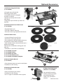
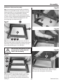
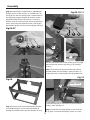
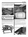
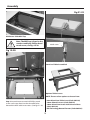
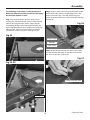
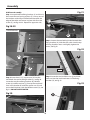
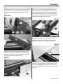
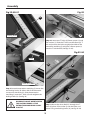
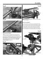
Assembly
Step 5 Locate the fence assembly (H), ‘T’ bolts (d) and
flat washers (i). Insert six ‘T’ bolts into the pre-drilled
holes in the fence (H), place a washer (i) on each ‘T’
bolt and screw on the locking knobs (b). (See figs
34-35)
Fig 34-35
Step 7 Locate the two locking handle knobs (a) and
flat washers (i). Line up the machined slots in the
fence (H) with the two locking Hex nuts (g) in the
fixing bracket (K). Place a washer (i) over the thread
on the locking handle knobs (a), screw the handle
knobs through the fence base clamping the fence
assembly to the table top. (See fig 37).
Fig 37
H
a
b
i
d
H
i
Machined slot
Step 8 Slide the fence assembly forward until
the front face lines up with engraved index line
embedded in the table, (see fig 38) clamp down
Fig 38
Step 6 Locate the two adjustable wood faces (M),
lineup the ‘T’ bolts (d) with the ‘T’ slots in the wood
face (M) and slide on the wood face, lightly tighten.
(See fig 36). Repeat for the other side.
Engraved line
Fig 36
the fence assembly. Loosen the two locking knobs
beneath the fixing brackets (K), slide the two scales
until it reads (ZERO) to the front face of the fence
assembly, lightly tighten the locking knobs. (See figs
39-40-41)
d
M
17
Continues Over...