1
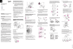
Using ARGUS with alarm systems
KNX ARGUS 220
Operating instructions
Art. no. MTN6325..
|
Movement detectors are not suitable for use as
components of an alarm system.
|
Movement detectors can trigger false alarms if
the installation site has been chosen unfavourably.
Movement detectors switch on as soon as they detect a
moving heat source. This can be a person, but also animals, trees, cars or differences in temperature in windows. In order to avoid false alarms, the chosen
installation site should be such that undesired heat
sources cannot be detected.
Undesired sources of heat could include the following:
• moving trees, shrubbery etc. with a temperature that
differs from that of their surroundings.
• windows where the influence of sunlight and clouds
could cause rapid changes in temperature.
Accessories
• larger heat sources (e.g. cars), that are detected
through windows.
– Mounting bracket (Art. no. MTN565291)
• insects moving across the lens.
– Programming magnet for EMO valve drive (Art. no.
MTN639190)
• small animals.
• rooms flooded with light where the light is reflected on
objects (e.g. the floor), which can be the cause of rapid
changes in temperature.
For your safety
¼
DANGER
Risk of fatal injury from electrical current.
All work carried out on the unit may only be performed by skilled electricians. Observe the regulations valid in the country of use, as well as the
valid KNX guidelines.
The ARGUS 220 (subsequently called ARGUS) is a
KNX movement detector which can be used both indoors and outdoors due to its IP 55 protection rating.
Surface monitoring of 220° for larger house fronts and areas of the house (max. range of 16 m) is combined with
a 360° short-range zone with a radius of approx. 4 m.
The operating elements for setting the brightness, time
and sensitivity (range) as well as the programming area
and a red LED for displaying the programming are located under the cover plate for protection. The physical address is programmed using a programming magnet (e.g.
art. no. MTN639190).
The ARGUS can be mounted on the wall or ceiling and
also on to corners or fixed pipes with the mounting
bracket (art. no. MTN5652 ..) which is available as an accessory.
B
G
F
∞
C
E
D
D
A Sensitivity controller
D Select a mounting height between 2 m and 3 m. For
optimum monitoring, we recommend a height of 2.5
m on a solid and even base.
B Time controller
C Brightness controller
D Functional display, lights up each time movement is
detected
E Brightness sensor
F Programming area for magnet
G Programming LED
Selecting the installation site
Explanation of the symbols used
3 Feed in the bus line.
– To feed the bus line into the back of the device
from above, attach the spacers supplied to the
wall connection box.
To avoid the connected load being switched on due to
environmental influences, the ARGUS should be installed so that it is protected against rain and direct sunlight. A raindrop running over the lens, for example, can
activate the movement detector.
E
E
CAUTION
The device can become damaged.
If installation is not carried out correctly, water can
penetrate the movement detector and damage it.
Always mount it with the spherical head pointing
downwards.
– Feeding in the bus line from behind: slide the rubber grommet A supplied over the stripped bus
line.
E Maintain a distance of at least 5 m from sources of
optical interference. Use the masking segments
provided if necessary.
– Feeding in the bus line from below: cut the rubber
insert B supplied according to the cable thickness. Insert the rubber insert into the wall connection box. Push the bus line through.
In principle, you should not mount the luminaire underneath the ARGUS. The radiated heat from the luminaire
can influence the function of the movement detector and
lead to a permanent lighting circuit under certain conditions.
A
OK
OK
Correct
Connections, displays and operating
elements
Not optimal
F
Incorrect
A
B
C
H
ARGUS introduction
½
A
G
B
When selecting a suitable installation site, you should
take a number of factors into account so that the movement detector operates optimally.
The following diagram shows the ranges of the ARGUS.
They are based on average temperature conditions at a
mounting height of 2.5 m. The range of a movement detector can fluctuate considerably at variable temperatures.
F A minimum distance of 5 m should be maintained
between the luminaire and the movement detector.
If this distance cannot be achieved, you can use the
segments provided to "mask" the light source from
the area of detection.
If you wish to attach several movement detectors, install
them so that the detection areas of the individual movement detectors intersect each other.
4 Mount the wall connection box.
If possible, install the movement detector sideways to the
direction of movement.
m
F
E
2,5
D
0
A Wall connection box
12
B Top section
10
C Cover plate
8
0,8 m
4
0
2
4
6
14
8
B
A
10 12 14 16 m
C
OK
6
D Sensor head
ARGUS installation
1 Undo both screws and remove the wall connection
box from the device.
4
E Contact pins
F Cable routing for bus line from underneath
2
0
G Cable routing for bus line from behind
2
H Terminal block for connecting the bus line and for locating the contact pins
6
The integrated functional display lights up when movement is detected and thus simplifies the alignment of the
device at the installation site. You can also optionally
switch off the functional display via a parameter setting.
In order to install the ARGUS on the ceiling, you must rotate the sensor head. Change the direction of rotation
once you have reached the end stops.
1 Turn the sensor head upwards as far as it will go.
OK
4
Installing the ARGUS on the ceiling
2 Turn the sensor head clockwise as far as it will go.
3 Align the sensor head.
8
10
12
14
4
2
0
2
4
6
8
10 12 14 16 m
The area of detection can be adapted to the local conditions due to the horizontally, vertically and axially adjustable sensor head. You can also block unwanted zones or
sources of interference (e.g. trees) from the area of detection using the masking segments provided.
A Inner security zone with an angle of detection of
360° and a radius of approx. 4 m.
The device is fitted with a light sensor whose brightness
threshold can be set from approx. 3 to 1000 lux. Depending on the application, it is also possible to use the device
as a light-sensitive switch or to link the brightness threshold with the detection of movement. Several movement
detectors can be combined together in a system.
C Outer security zone with an angle of detection of
220° and a detection area of approx. 16 m x 28 m.
OK
2 Mark drill holes on the mounting surface.
B Central security zone with an angle of detection of
220° and an area of detection of approx.
9 m x 18 m.
The power is supplied via the bus line. No additional
mains connection is required. As the bus line is connected directly to the terminal block in the wall connection
box, a bus connecting terminal is not required.
1
1
2
3
Bus
V6325-561-00 03/08
GB
Using ARGUS with alarm systems
KNX ARGUS 220
Operating instructions
Art. no. MTN6325..
|
Movement detectors are not suitable for use as
components of an alarm system.
|
Movement detectors can trigger false alarms if
the installation site has been chosen unfavourably.
Movement detectors switch on as soon as they detect a
moving heat source. This can be a person, but also animals, trees, cars or differences in temperature in windows. In order to avoid false alarms, the chosen
installation site should be such that undesired heat
sources cannot be detected.
Undesired sources of heat could include the following:
• moving trees, shrubbery etc. with a temperature that
differs from that of their surroundings.
• windows where the influence of sunlight and clouds
could cause rapid changes in temperature.
Accessories
• larger heat sources (e.g. cars), that are detected
through windows.
– Mounting bracket (Art. no. MTN565291)
• insects moving across the lens.
– Programming magnet for EMO valve drive (Art. no.
MTN639190)
• small animals.
• rooms flooded with light where the light is reflected on
objects (e.g. the floor), which can be the cause of rapid
changes in temperature.
For your safety
¼
DANGER
Risk of fatal injury from electrical current.
All work carried out on the unit may only be performed by skilled electricians. Observe the regulations valid in the country of use, as well as the
valid KNX guidelines.
The ARGUS 220 (subsequently called ARGUS) is a
KNX movement detector which can be used both indoors and outdoors due to its IP 55 protection rating.
Surface monitoring of 220° for larger house fronts and areas of the house (max. range of 16 m) is combined with
a 360° short-range zone with a radius of approx. 4 m.
The operating elements for setting the brightness, time
and sensitivity (range) as well as the programming area
and a red LED for displaying the programming are located under the cover plate for protection. The physical address is programmed using a programming magnet (e.g.
art. no. MTN639190).
The ARGUS can be mounted on the wall or ceiling and
also on to corners or fixed pipes with the mounting
bracket (art. no. MTN5652 ..) which is available as an accessory.
The integrated functional display lights up when movement is detected and thus simplifies the alignment of the
device at the installation site. You can also optionally
switch off the functional display via a parameter setting.
B
G
F
∞
C
E
D
D
A Sensitivity controller
D Select a mounting height between 2 m and 3 m. For
optimum monitoring, we recommend a height of 2.5
m on a solid and even base.
B Time controller
C Brightness controller
D Functional display, lights up each time movement is
detected
E Brightness sensor
F Programming area for magnet
G Programming LED
Selecting the installation site
Explanation of the symbols used
3 Feed in the bus line.
– To feed the bus line into the back of the device
from above, attach the spacers supplied to the
wall connection box.
To avoid the connected load being switched on due to
environmental influences, the ARGUS should be installed so that it is protected against rain and direct sunlight. A raindrop running over the lens, for example, can
activate the movement detector.
E
E
CAUTION
The device can become damaged.
If installation is not carried out correctly, water can
penetrate the movement detector and damage it.
Always mount it with the spherical head pointing
downwards.
– Feeding in the bus line from behind: slide the rubber grommet A supplied over the stripped bus
line.
E Maintain a distance of at least 5 m from sources of
optical interference. Use the masking segments
provided if necessary.
– Feeding in the bus line from below: cut the rubber
insert B supplied according to the cable thickness. Insert the rubber insert into the wall connection box. Push the bus line through.
In principle, you should not mount the luminaire underneath the ARGUS. The radiated heat from the luminaire
can influence the function of the movement detector and
lead to a permanent lighting circuit under certain conditions.
A
OK
OK
Correct
Connections, displays and operating
elements
Not optimal
F
Incorrect
A
B
C
H
ARGUS introduction
½
A
G
B
When selecting a suitable installation site, you should
take a number of factors into account so that the movement detector operates optimally.
The following diagram shows the ranges of the ARGUS.
They are based on average temperature conditions at a
mounting height of 2.5 m. The range of a movement detector can fluctuate considerably at variable temperatures.
F A minimum distance of 5 m should be maintained
between the luminaire and the movement detector.
If this distance cannot be achieved, you can use the
segments provided to "mask" the light source from
the area of detection.
If you wish to attach several movement detectors, install
them so that the detection areas of the individual movement detectors intersect each other.
4 Mount the wall connection box.
If possible, install the movement detector sideways to the
direction of movement.
m
F
E
2,5
D
0
A Wall connection box
12
B Top section
10
C Cover plate
8
D Sensor head
E Contact pins
F Cable routing for bus line from underneath
0,8 m
4
0
2
4
6
14
8
B
A
10 12 14 16 m
C
OK
ARGUS installation
1 Undo both screws and remove the wall connection
box from the device.
6
4
2
0
G Cable routing for bus line from behind
2
H Terminal block for connecting the bus line and for locating the contact pins
6
In order to install the ARGUS on the ceiling, you must rotate the sensor head. Change the direction of rotation
once you have reached the end stops.
1 Turn the sensor head upwards as far as it will go.
OK
4
Installing the ARGUS on the ceiling
2 Turn the sensor head clockwise as far as it will go.
3 Align the sensor head.
8
10
12
14
4
2
0
2
4
6
8
10 12 14 16 m
The area of detection can be adapted to the local conditions due to the horizontally, vertically and axially adjustable sensor head. You can also block unwanted zones or
sources of interference (e.g. trees) from the area of detection using the masking segments provided.
A Inner security zone with an angle of detection of
360° and a radius of approx. 4 m.
The device is fitted with a light sensor whose brightness
threshold can be set from approx. 3 to 1000 lux. Depending on the application, it is also possible to use the device
as a light-sensitive switch or to link the brightness threshold with the detection of movement. Several movement
detectors can be combined together in a system.
C Outer security zone with an angle of detection of
220° and a detection area of approx. 16 m x 28 m.
OK
2 Mark drill holes on the mounting surface.
B Central security zone with an angle of detection of
220° and an area of detection of approx.
9 m x 18 m.
1
2
3
Bus
The power is supplied via the bus line. No additional
mains connection is required. As the bus line is connected directly to the terminal block in the wall connection
box, a bus connecting terminal is not required.
2
V6325-561-00 03/08
GB
Setting the sensitivity
Putting ARGUS into operation
½
|
CAUTION
If not installed correctly, the device can be
damaged by condensation.
In the case of sloping ceilings, install the device
so that spherical head is pointing down and always at an angle of 15° - 90°. When the spherical
head points downwards, any water from condensation could run down the device.
The ARGUS operating elements are protected under a
cover plate. The arrow's position on the controllers
shows you the set values.
1 Push up the cover plate until you feel it hit the stop
(approx. 5 mm) and pull it off.
Type of protection IP 55 cannot be guaranteed if
the mounting bracket is not 15° - 90°.
15° - 90°
Setting the brightness threshold
2 Guide a programming magnet (e.g. art. no.
MTN639190) over the programming area.
The programming LED lights up.
3 Load the physical address and application into the
device from the ETS.
The programming LED goes out when the application
has been loaded successfully. This device is ready for
operation.
Installing the ARGUS on corners and fixed pipes
You can attach the ARGUS to inner/outer corners or fixed
pipes using the Merten mounting bracket (art. no.
MTN5652..). You can feed the bus line to the device from
behind through the mounting bracket.
The brightness sensor must not be covered up.
KNX
+-
3 LUX
1000 LUX
∞
2 Set the brightness controller to daytime operation
(infinity symbol/right-hand stop) or select the setting
"independent of brightness" in ETS.
½
CAUTION
The device could become damaged.
The sensor head should only be rotated until it
reaches the stop and no further. To achieve an
angle "above" the stop, change the direction of
rotation.
1 Align the sensor head in the direction of the area
that is to be monitored.
Setting the time
This makes it possible to set the overshoot time of the
connected loads. This is the time period from the last detected movement until the load is switched off. Depending on the ETS application, the overshoot time is either
set in the ETS program (infinitely variable between
3 seconds and 152 hours) or directly on the ARGUS (six
steps of approx. 1 second to approx. 8 minutes).
|
Once the load has been switched on, the set
brightness threshold is ignored. Depending on
the settings in ETS, each registered movement
can reset the overshoot time. If the movement detector no longer switches off, it is probably because it is continually detecting new movement
and is thus always extending the overshoot time.
9°
24°
12° 12°
12°
Nominal voltage:
KNX connection:
Power consumption:
Angle of detection:
Range:
Number of levels:
Number of zones:
Minimum
mounting height:
Recommended
mounting height:
Sensitivity:
Light sensor:
Time:
Programming:
Display elements:
DC 24 V (+6 V / -4 V)
via terminal block
approx. 7 mA
220°
max. 16 m
7
112 with 448 switching segments
1.7 m
2.5 m
infinitely adjustable externally
infinitely adjustable externally,
from approx. 3 lux to approx.
1000 lux
infinitely adjustable in the software from 3 seconds to 152 hours
or adjustable externally in 6
steps from approx. 1 second to
approx. 8 minutes.
magnet-sensitive sensor for assigning the physical address.
1 red LED: Programming check,
1 red LED: Functional display
Possible settings for
the sensor head:
Wall mounting:
9° up, 24° down, 12° left/right,
± 12° axial
Ceiling mounting: 4° up, 29° down, 25° left/right,
± 8.5° axial
Type of protection:
IP 55 at an angle of inclination
from 15° to 90°
Ambient temperature: -25 °C to +55 °C
EC guidelines:
Low Voltage guideline 73/23/
EEC,
EMC guideline 89/336/EEC
Initialisation:
Due to the limitation of the telegram rate, a telegram cannot be
generated until at least 17 s after
the initialisation.
Schneider Electric Industries SAS
If you have technical questions, please contact the Customer Care Center in your country.
www.schneider-electric.com
Blocking out individual areas
Using the four segments supplied, you can block out unwanted zones and sources of interference from the area
of detection.
You can wire the bus line through the two terminals (+) and (–) without encountering problems.
Technical data
– Sun symbol: The ARGUS detects movements up to
approx. 1000 lux.
Depending on the application program, you can either
set the time in the software or on the device.
Setting ARGUS
14 mm
– Moon symbol (left stop) The ARGUS will only detect
movements during the hours of darkness (approx. 3
lux).
1 Set the time controller to 1 second (left-hand stop).
The functional display lights up each time movement is
detected.
Connecting KNX
Here you can infinitely set the ambient brightness level at
which the ARGUS detects movements and triggers a
switching procedure.
– Infinity symbol (right-hand stop): The ARGUS detects
movements regardless of the ambient brightness.
Conducting a functional test
3 Set the sensitivity controller to maximum (righthand stop).
|
Here you can infinitely set the distance up to which ARGUS detects movements (any distance up to max.
16 m).
This product must be installed, connected and used in
compliance with prevailing standards and/or installation
regulations. As standards, specifications and designs
develop from time to time, always ask for confirmation of
the information given in this publication.
A
12°
Installation of the top section of the ARGUS
1 Place the top section on the wall connection box
from the front.
2 Fasten the top section with the screws provided.
The electrical connection from the terminal box to the
contact pins is established automatically when the
screws are tightened.
3 Position the cover plate at the markings on the side,
and guide it upwards.
1
2
25°
25°
8,5° 8,5°
2 From its edge step into the area of detection to see
whether the ARGUS switches the load and the functional display as required.
|
Ensure that the brightness sensor A is not covered, as the sensitivity to light is otherwise reduced.
3
3
V6325-561-00 03/08
2
1
4° 29°
Setting the sensitivity
Putting ARGUS into operation
½
|
CAUTION
If not installed correctly, the device can be
damaged by condensation.
In the case of sloping ceilings, install the device
so that spherical head is pointing down and always at an angle of 15° - 90°. When the spherical
head points downwards, any water from condensation could run down the device.
The ARGUS operating elements are protected under a
cover plate. The arrow's position on the controllers
shows you the set values.
1 Push up the cover plate until you feel it hit the stop
(approx. 5 mm) and pull it off.
Type of protection IP 55 cannot be guaranteed if
the mounting bracket is not 15° - 90°.
15° - 90°
Setting the brightness threshold
2 Guide a programming magnet (e.g. art. no.
MTN639190) over the programming area.
The programming LED lights up.
3 Load the physical address and application into the
device from the ETS.
The programming LED goes out when the application
has been loaded successfully. This device is ready for
operation.
Installing the ARGUS on corners and fixed pipes
You can attach the ARGUS to inner/outer corners or fixed
pipes using the Merten mounting bracket (art. no.
MTN5652..). You can feed the bus line to the device from
behind through the mounting bracket.
The brightness sensor must not be covered up.
KNX
+-
3 LUX
1000 LUX
∞
2 Set the brightness controller to daytime operation
(infinity symbol/right-hand stop) or select the setting
"independent of brightness" in ETS.
½
CAUTION
The device could become damaged.
The sensor head should only be rotated until it
reaches the stop and no further. To achieve an
angle "above" the stop, change the direction of
rotation.
1 Align the sensor head in the direction of the area
that is to be monitored.
Technical data
Nominal voltage:
KNX connection:
Power consumption:
Angle of detection:
Range:
Number of levels:
Number of zones:
Minimum
mounting height:
Recommended
mounting height:
Sensitivity:
Light sensor:
Time:
– Sun symbol: The ARGUS detects movements up to
approx. 1000 lux.
Depending on the application program, you can either
set the time in the software or on the device.
Setting ARGUS
14 mm
– Moon symbol (left stop) The ARGUS will only detect
movements during the hours of darkness (approx. 3
lux).
1 Set the time controller to 1 second (left-hand stop).
The functional display lights up each time movement is
detected.
Connecting KNX
Here you can infinitely set the ambient brightness level at
which the ARGUS detects movements and triggers a
switching procedure.
– Infinity symbol (right-hand stop): The ARGUS detects
movements regardless of the ambient brightness.
Conducting a functional test
3 Set the sensitivity controller to maximum (righthand stop).
|
Here you can infinitely set the distance up to which ARGUS detects movements (any distance up to max.
16 m).
Setting the time
This makes it possible to set the overshoot time of the
connected loads. This is the time period from the last detected movement until the load is switched off. Depending on the ETS application, the overshoot time is either
set in the ETS program (infinitely variable between
3 seconds and 152 hours) or directly on the ARGUS (six
steps of approx. 1 second to approx. 8 minutes).
|
Once the load has been switched on, the set
brightness threshold is ignored. Depending on
the settings in ETS, each registered movement
can reset the overshoot time. If the movement detector no longer switches off, it is probably because it is continually detecting new movement
and is thus always extending the overshoot time.
Programming:
Display elements:
DC 24 V (+6 V / -4 V)
via terminal block
approx. 7 mA
220°
max. 16 m
7
112 with 448 switching segments
1.7 m
2.5 m
infinitely adjustable externally
infinitely adjustable externally,
from approx. 3 lux to approx.
1000 lux
infinitely adjustable in the software from 3 seconds to 152 hours
or adjustable externally in 6
steps from approx. 1 second to
approx. 8 minutes.
magnet-sensitive sensor for assigning the physical address.
1 red LED: Programming check,
1 red LED: Functional display
Possible settings for
the sensor head:
Wall mounting:
9° up, 24° down, 12° left/right,
± 12° axial
Ceiling mounting: 4° up, 29° down, 25° left/right,
± 8.5° axial
Type of protection:
IP 55 at an angle of inclination
from 15° to 90°
Ambient temperature: -25 °C to +55 °C
EC guidelines:
Low Voltage guideline 73/23/
EEC,
EMC guideline 89/336/EEC
Initialisation:
Due to the limitation of the telegram rate, a telegram cannot be
generated until at least 17 s after
the initialisation.
Blocking out individual areas
Using the four segments supplied, you can block out unwanted zones and sources of interference from the area
of detection.
You can wire the bus line through the two terminals (+) and (–) without encountering problems.
9°
24°
12° 12°
12°
A
12°
Installation of the top section of the ARGUS
1 Place the top section on the wall connection box
from the front.
The electrical connection from the terminal box to the
contact pins is established automatically when the
screws are tightened.
3 Position the cover plate at the markings on the side,
and guide it upwards.
1
2
1
2
4° 29°
25°
25°
8,5° 8,5°
2 From its edge step into the area of detection to see
whether the ARGUS switches the load and the functional display as required.
Schneider Electric Industries SAS
|
Ensure that the brightness sensor A is not covered, as the sensitivity to light is otherwise reduced.
If you have technical questions, please contact the Customer Care Center in your country.
www.schneider-electric.com
This product must be installed, connected and used in
compliance with prevailing standards and/or installation
regulations. As standards, specifications and designs
develop from time to time, always ask for confirmation of
the information given in this publication.
3
4
V6325-561-00 03/08
2 Fasten the top section with the screws provided.
suit requirements. Check the "Brightness" and "Times"
tabs.
In this way the corresponding objects are connected
to a KNX switch actuator.
Movement/monitoring 1307/1.0
● General
In the following the device will be referred to as the
movement detector.
The movement block will only switch off when there is
no more movement in front of the device - in other
words, independently of the brightness.
The ETS application includes 5 independent
movement blocks, each with 4 output objects.
|
Switch
Actuator
Status feedback obj.
Safety pause
Note:
All of the settings described refer to ETS version
3, but you can also use all the settings and
functions with ETS version 2.
The application files (vd2 and vd3) are
configured in such a way that the application
loading time is considerably reduced. When you
convert an ETS 2 project to ETS 3, you lose this
time saving. If you are working with ETS 3, use
the vd3 files.
Total possible addresses and connections:
254 addresses; 255 connections
1/1/2
Status feedback obj.
To familiarise yourself with the extended and more
complex parameters see the following pages.
● General functions
The common safety pause
The application has a common safety pause system in other words, a safety pause triggered by the
movement detector will affect all blocks in the
application. As specified in a parameter the safety
pause can be triggered at the status feedback object
(safety pause) when there is an OFF telegram or when
there is an OFF and ON telegram.
The status feedback object of the switching/dimming
actuator must be connected to the feedback safety
pause object of the movement detector.
Once a safety pause has been started, signals from
the movement sensor will no longer be evaluated for
this period of time. An elapsed staircase timer cannot
be started by a movement during an active safety
pause and an ongoing staircase timer cannot be
retriggered by a movement.
An ongoing staircase timer is not affected by a safety
pause being activated. In other words, the staircase
timer will run through in the usual way.
Note:
ETS 2 or ETS 3 (by clicking "Standard"), all the
values that you have changed so far will be
deleted. Any group addresses which have been
parametrised will be lost.
Note:
Due to the fact that various functions depend
on other functions, these dependent functions
will not be visible and selectable in the ETS
unless the preceding function has been
enabled. If you de-select functions or change
parameters, group addresses that have already
been connected may be removed.
● Getting started quickly
| Optical feedback can only be avoided by
Note:
When you insert the application in the ETS or click on
the "Standard" button, the ETS application will switch
automatically to minimum configuration.
In minimum configuration, it is possible to put the
presence detector into operation. For some
application cases, the minimum configuration is even
adequate for practical use. We also recommend
opening minimum configuration as a way of
familiarising yourself with the application software for
the presence detector. Here all of the extended or
more complex parameters are disabled. In "Block
configuration" only the first "Movement" block is
enabled for use. In the "Telegrams" tab only output
object 1 is enabled. This is a 1-bit output object. At the
start of movement this object sends a 1 telegram and
when the internal staircase timer has elapsed it sends
a 0 telegram. Each parameter can always be tuned to
its individual requirements. The brightness threshold
and the staircase timer always need to be adjusted to
© 2008 Schneider Electric
Switch object
Movement
Detector
| If you switch back to the preset values in either
|
1/1/1
Switch object
selecting the right installation location for the
movement detector and the lighting. The safety
pause system and the safety pause object of
the application cannot compensate for all
planning mistakes.
Communication objects
You can select the following communication objects:
General:
5
Function
Object name
Type
Prio
Flags Behaviour
Safety
pause
Status feedback
object
1 bit
Low
WC
Receive
an ON telegram to the bus. When no further
movement is detected the staircase timer starts. An
OFF telegram is transmitted to the bus after a
parametrised time.
Brightness is measured only at the moment when
the first movement is detected. If further movement is
detected, an OFF telegram is not transmitted,
irrespective of brightness changes. The staircase
timer starts only when movement is no longer
detected, and an OFF telegram is transmitted after the
parametrised time period.
Parameter
| The parameter settings include various
Note:
functions which depend on other functions.
Depending on the parameter setting, some
functions or objects may or may not be
displayed in the ETS.
General
Parameter
Setting
Safety pause via status feedback Disabled
object
For OFF telegram
Block configuration
For ON and OFF telegram
Safety pause (1 - 20) seconds
Up to five movement blocks are available. In the
default setting, block 1 is enabled.
1-20, preset: 2
● General brightness evaluation:
Parameter
The current brightness can be determined by the
internal brightness sensor, by an external
communication object or by both dependencies. The
relationship between internal and external values can
be parametrised while doing this.
Block configuration
Parameter
Setting
Movement block X
Enabled
Disabled
Communication objects
Movement detection
You can select the following communication objects:
The device has a detection angle of 220°.
General:
To suppress disturbance variables or if delayed
activation is required, a dead time for the start of
movement can be activated. The dead time is started
after movement has been detected (start of
movement). The start of movement action
(transmitting a telegram to the bus) can take place if a
movement is still detected within the movement time
after the dead time has elapsed.
Function
Object name
Type
Prio
Flags Behaviour
External
sensor
Actual value input 2
bytes
Low
WCT Transmit/
U
receive/
update
Parameter
From internal sensor
From object, actual value input
From internal sensor and object
0% - 100%, in 5% steps;
preconfiguration 50%
Movement
Taking the separately measured
lux value (0% - 100%) into
account
For actual value correction you will need a luxmeter.
The measured values are then input into the
application software of the presence detector.
When intense sunlight is shining onto the reference
area or the installation location, the measurements
should not be taken. Under certain circumstances
darkening the room may improve the measurement
results.
Dead
Time
Movement
Time
Movement
Time
Movement
Time
Dead Movement
Time Time
OFF
Setting
Actual value (brightness)
ON
Parameter
Switch object
General
Time
Time
● Movement block
In master mode or normal mode the movement time
corresponds to the staircase timer in the diagram
above. In slave mode or monitoring mode the
movement time corresponds to the cycle time. In
practice a large number of applications can be
implemented by means of the various blocks.
Basic function of a movement block
Block diagram of movement block
A staircase timer is "integrated" into a movement
block. When the ambient brightness is too low and a
movement is detected, the movement block transmits
A block diagram clarifies the relationships between the
individual dependencies.
© 2008 Schneider Electric
6
Communication objects
Move
Sensor
You can select the following communication objects:
Movement
detection
Master
Trigger
Block X, general movement sensors:
Brightness
sensor
Brightness obj.
Brightness
evaluation
Function
Object name
Type
Block X
Range
1 byte Low
Prio
Flags Behaviour
WC
Receive
Parameter
Alwaysdark obj.
Times
Telegrams
Note:
| The parameter settings include various
Trigger obj.
Disable obj.
Disable
function
functions which depend on other functions.
Depending on the parameter setting, some
functions or objects may or may not be
displayed in the ETS.
Output obj.
1-4
Movement evaluation
Block X, general - movement
sensors
As has already been stated above, the movement
sensor input into movement detection.
The master trigger object is brightness-dependent and
with an ON telegram simulates a movement; an OFF
telegram is ignored.
The trigger object is brightness-independent and also
simulates a movement for an ON telegram . Whether
the trigger object can switch the lighting off early
when there is an OFF telegram can be parametrised.
Parameter
Advanced settings
Enabled
Disabled
The following settings are only
visible when "Disabled".
Sensitivity (for all sensors)
High
Medium
Low
Range adjustable
Potentiometer
Parameter
| The master trigger object and the trigger object
Note:
Range
(only visible by "Parameter")
do not appear in the ETS until the device
operating mode has been set to "Master mode".
See "Block X, general" tab, parameter:
"Operating mode". The master/trigger object
ignores the dead time (for Dead time, see
above) and reacts without a delay. More
detailed information about the master/trigger
object may be found later on.
© 2008 Schneider Electric
Setting
10% - 100% (in 10% steps)
preconfiguration: 100%
The following settings are only
visible when "Enabled".
Range object (for all sensors)
Disabled
Enabled
Dead time, start of movement (for Disabled
all sensors)
Enabled
7
Time base
1 min, 1s
Time factor (1 - 255)
3, (1-255)
Brightness object 1 bit
Block X, general movement
sensors sector X
Parameter
Setting
Sensitivity
High
The brightness object sends a 1-bit value on the bus. If
the parametrised brightness threshold is not reached,
an ON telegram can be transmitted. If the
parametrised brightness threshold is exceeded, an
OFF telegram can be transmitted. Inverted
transmission can also be set.
Medium
Low
Range adjustable
Via parameters
Via Potentiometer
Overwrite range during download Enabled
Too bright
Brightness threshold
Brightness
Disabled
Range
10% - 100% (in 10% steps)
preconfiguration: 100%
Change range via object
Disabled
Too dark
t
ON
ON
Enabled
OFF
Brightness
object
t
● Brightness evaluation
Always-dark object
Brightness evaluation of a movement detector:
Brightness
In the case of an enabled "always-dark object",
darkness can be simulated internally in the movement
detector depending on the object value. The "alwaysdark object" is used with master/slave circuits.
Planning master/slave circuits is described further
below.
Staircase timer
Staircase timer
Staircase timer
Staircase timer
Staircase timer
Brightness
threshold
Time
Switch object
Movement
OFF
ON
Communication objects
You can select the following communication objects:
Time
Block X, general brightness:
Time
The movement detector changes to non-brightnessdependent mode once the start of movement action
(sending an ON telegram) has been carried out. Here
freshly detected movements can retrigger the
staircase timer. The movement detector cannot
process the brightness jump and there is not even any
setting of a hysteresis.
Object name
Type
Prio
Flags Behaviour
Block X
Brightness
threshold
2
bytes
Low
WC
Receive
Block X
Brightness object 1 bit
Low
CT
Transmit
Block X
Always-dark
object
Low
WC
Receive
1 bit
Note:
| The parameter settings include various
functions which depend on other functions.
Depending on the parameter setting, some
functions or objects may or may not be
displayed in the ETS.
Brightness
The brightness threshold can be parametrised
separately for each of the five movement blocks. Each
block has its own "Brightness" tab. A staircase timer be
started (depending on parametrisation of the device)
and an ON telegram transmitted to the bus only after
the value is below the parametrised brightness
threshold and the movement detector detects a
movement. The brightness threshold can be set
between 3 and 1000 lux.
Via the "Brightness threshold object" "Enabled" or
"Disabled" you can select whether the brightness
threshold should be changed via the bus. This can be
useful when several movement detectors are installed
in a building. The brightness threshold can be changed
using the "Brightness threshold - Block X" object via
the ETS or an IP touch panel, for example. The
brightness threshold is set to the same level in all parts
of the building.
© 2008 Schneider Electric
Function
8
Parameter
Master mode
Block X, general brightness
With master mode all of the possible parameters and
communication objects of the movement detector are
available. A master-slave system can be set up with
the aid of the master trigger object or the trigger
object. In the default setting, the movement detector
transmits an ON telegram at the start of movement
and transmits an OFF telegram when the movement
time (staircase timer) has expired.
Parameter
Setting
Movement detection is
brightness-dependent
independent of brightness
Brightness threshold adjustable
via
Parameters
Potentiometer
Overwrite brightness threshold
during download
Enabled
Slave mode
Disabled
Brightness threshold (3 - 1000 lux) 3 - 1000 lux; preconfiguration:
see "General" tab
130
Brightness threshold object
In slave mode the default setting is that ON telegrams
are sent cyclically when a movement is detected.
These telegrams are intended for the master trigger
object or for the trigger object of the master.
Disabled
Enabled
Brightness object 1 bit
Do not send
Transmit
Monitoring mode
Transmit inverted
Always-dark object (= not
brightness-dependent)
In monitoring mode the default setting is that ON
telegrams are sent cyclically when a movement is
detected. At the end of the movement time (cycle
time with movement) OFF telegrams are transmitted
cyclically.
Disabled
Enabled
Switch on at movment
Enabled
Disabled
Note:
| Use the "Monitoring mode" setting when the
● Operating modes
movementmovement detector is being used for
room monitoring and telegrams are to be sent
cyclically on the bus.
The operating mode in which this block operates is
specified in the application software for each block
(movement blocks 1 - 5). The following operating
modes are available:
– Normal operation
– Master mode
– Slave mode
– Monitoring mode
Depending on the operating mode different
parameters and communication objects will be
displayed. Each operating mode can operate
brightness-dependently or non-brightnessdependently.
Normal operation
In this operating mode the movement detector does
not have any external trigger objects (master trigger
object, trigger object). Telegrams cannot be sent
cyclically and this means a master-slave system
cannot be set up. In the default setting, the movement
detector transmits an ON telegram at the start of
movement and transmits an OFF telegram when the
movement time (staircase timer) has expired.
Note:
| Use the "Normal operation" setting when the
movement detector is working for itself alone.
In other words, one movement detector is used
for each room and it switches one light or one
light panel.
© 2008 Schneider Electric
9
Master mode:
– "Send after staircase timer/remaining time has
elapsed"
– "Send after staircase timer has elapsed and then
cyclically"
– "Do not send"
Slave mode:
– "Do not send" (is permanent setting in the
background of the application software, is not
displayed in the parameters)
Monitoring mode:
– "Send at end of cycle time when there is movement
and then cyclically" (is permanent setting in the
background of the application software, is not
displayed in the parameters)
Communication objects
You can select the following communication objects:
Block X, general:
Function
Object name
Type
Prio
Flags Behaviour
Block X
Master trigger
object
1 bit
Low
WC
Receive
Block X
Trigger object
1 bit
Low
WC
Receive
The
objects
are only
visible in
"Master
mode"
operating
mode.
Parameter
Four output objects are available for each of the five
movement blocks and they can be enabled via the
application software. A transmission pause between
the individual output objects can be set for each block.
Block X, general
Parameter
Setting
Operating mode
Normal operation
Master mode
Slave mode
Note:
| Five movement blocks and four output objects
Monitoring mode
per movement detector means that 20
switching/value objects in all are available.
Note:
| When toggling between operating modes the
"Brightness" and "Times" tabs change.
● Telegrams
For each movement block the "Action at start of
movement" can be set as a function of the operating
mode.
Normal operation:
– "Send immediately"
– "Do not send"
Master mode:
– "Send immediately"
– "Send immediately and then cyclically"
– "Do not send"
Slave mode:
– "Send immediately and then cyclically" (is
permanent setting in the background of the
application software, is not displayed in the
parameters)
Monitoring mode:
– "Send immediately and then cyclically" (is
permanent setting in the background of the
application software, is not displayed in the
parameters)
The behaviour after the "End of movement time" can
also be set as a function of the operating mode.
Normal operation:
– "Send after staircase timer/remaining time has
elapsed"
– "Do not send"
© 2008 Schneider Electric
10
parameters will not be displayed!
The parameter settings include various
functions which depend on other functions.
Depending on the parameter setting, some
functions or objects may or may not be
displayed in the ETS.
Parameter
| The parameter settings include various
Note:
functions which depend on other functions.
Depending on the parameter setting, some
functions or objects may or may not be
displayed in the ETS.
Block X general telegrams
output switching/value object
X
Block X, general telegrams
Parameter
Setting
Action at start of movement
Send immediately
Parameter
Setting
Object
1 bit
1 byte 0% - 100%
Do not send
1 byte 0 - 255
Send immediately and then
cyclically
When movement time elapsed
2 bytes
Send after staircase timer/
remaining time has elapsed
At start of movement
Do not send
Value
Transmits its value
ON telegram
"Send after staircase timer/
remaining time has elapsed and
then cyclically"
Output object X (1 - 4)
Transmits defined value
OFF telegram
0% - 100%
0 - 255
Enabled
Disabled
When movement time elapsed
Transmits defined value
Value
ON telegram
Transmits its value
Pause between two telegrams (3 3 - 255; preconfiguration: 5
- 255) x 100 ms
OFF telegram
Output for switching/value object X
0% - 100%
For each output object you can select between a 1-bit,
1-byte (0% - 100%), 1-byte (0 - 255) and 2-byte object.
The telegram values should be parametrised for the
start of movement and for the end of the movement
time. Here an object can transmit its current value or a
defined value to the bus.
0 - 255
Note regarding 2-byte parameter settings:
| Depending on the setting of the object type
value there will be new parameters; depending
on the parametrisation the values can be input
immediately or are determined via sign x basic
value x factor.
| The current value can be transmitted by a time
Note:
switch, for example. During the night a lower
byte value is transmitted to the output object of
the movement detector than in daytime hours.
Communication objects
You can select the following communication objects:
Block X general - telegrams - output for switching/
value object X:
Function
Object name
Type
Prio
Flags Behaviour
Block X
Switch object X
1 bit
Low
WCT Transmit/
receive
Block X
Value object X
1 byte Low
WCT Transmit/
receive
Block X
Value object X
2
bytes
WCT Transmit/
receive
Low
Parameter
| The parameter settings shown below are
Note:
dependent on the operating mode and the
object settings (1 bit, 1 byte or 2 bytes).
Depending on the parametrisation some
© 2008 Schneider Electric
11
● Staircase timer
Parameter
Operating mode: Normal operation
The staircase timer or cycle time can be parametrised
via a time base x factor. With "Normal operation" and
"Master mode" operating modes the "Staircase timer"
is parametrised. With "Slave mode" and "Monitoring
mode" operating modes the "Cycle time" is
parametrised.
| The parameter settings include various
Note:
functions which depend on other functions.
Depending on the parameter setting, some
functions or objects may or may not be
displayed in the ETS.
The "Times" tab has some parameter displays
| and selectable objects which are dependent on
Block X, general times
the operating mode set.
|
Note:
In "Slave mode" and "Monitoring mode"
operating modes no further objects are
displayed by modification on the "Times" tab.
Parameter
Setting
Via movement, time is
Retriggerable
Not retriggerable
Staircase timer adjustable via
Parameters
Potentiometer
Overwriting staircase timer
during download
Enabled
Self-adjusting staircase timer
Disabled
Self-adjusting staircase timer
(always retriggerable)
The movementmovement detector is equipped with a
"Self-adjusting staircase timer". When the "Selfadjusting staircase timer" is enabled, the movement
detector can start a brief overshoot time when
someone is in the room for a short time. If they remain
in the room longer, a long overshoot time is started.
The parameters "Time base", "Minimum time factor",
"Time factor for learning step", "Maximum time factor"
and "Sensitivity of the learning step" are available for
the "Self-adjusting staircase timer." If there is only a
brief movement in front of the movement detector,
the overshoot time (until switch-off) will be close to the
"Minimum time factor" x "Time basis". If movements
last longer, a "Time factor for learning step" will be
added to the staircase timer up to the maximum,
depending on what learning sensitivity has been set.
Once the time set on the staircase timer has elapsed,
a restart takes place with "Minimum time factor".
Disabled
Enabled
The following settings are only
visible when "Self-adjusting
staircase timer" is "disabled".
Time factor staircase timer object Disabled
Enabled
Time base, staircase timer
1 min
1s
1 hr
Time factor for staircase timer (1 - 1 - 255; preconfiguration: 25
255)
The following settings are only
visible when "Self-adjusting
staircase timer" is "enabled".
Minimum time factor (1 - 255)
Staircase timer
1 - 255; preconfiguration: 5
Time factor for learning step (1 255) Staircase timer
1 - 255; preconfiguration: 1
Maximum time factor (1 - 255)
Staircase timer
1 - 255; preconfiguration: 25
Operating mode: Normal operation
You can select the following communication objects:
Sensitivity of learning step
1 - 5; preconfiguration: 4
1 = slow
5 = sensitive
Block X, general times:
Communication objects
Communication objects
Function
Object name
Type
Prio
Block X
Time factor,
staircase timer
1 byte Low
Operating mode: Master mode
You can select the following communication objects:
Flags Behaviour
WC
Transmit
Block X, general times:
Function
Object name
Type
Prio
Flags Behaviour
Block X
Master trigger
object
1 bit
Low
WC
Transmit
Block X
Trigger object
1 bit
Low
WC
Transmit
Block X
Time factor,
staircase timer
1 byte Low
WC
Transmit
Parameter
Operating mode: Master mode
Note:
| The parameter settings include various
functions which depend on other functions.
© 2008 Schneider Electric
12
Parameter
Operating mode: Slave mode
Depending on the parameter setting, some
functions or objects may or may not be
displayed in the ETS.
Block X, general times
Block X, general times
Parameter
Parameter
Setting
Cyclic interval during movement
Master triggering is (brightnessdependent)
Enabled
Time base
Via movement/master trigger
object, time is
Retriggerable
Disabled
1 hr
Time factor (1 - 255)
Master trigger object includes the Enabled
safety pause
Operating mode: Monitoring mode
Enabled
Note:
| No objects for "Time factor" or objects for
Disabled
Enabled
"Triggering" are displayed.
Disabled
Via trigger object, time is
Parameter
Operating mode: Monitoring mode
Retriggerable
Not retriggerable
Trigger object includes the safety Enabled
pause
Block X, general times
Parameter
Disabled
Staircase timer adjustable via
Self-adjusting staircase timer
(always retriggerable)
Parameters
Time base
1 hr
Disabled
Time factor (1 - 255)
Disabled
Cyclic interval when movement
time has elapsed
Enabled
Time base
1 - 255; preconfiguration: 5
1s
1 min
1 hr
Time factor (1 - 255)
Time factor staircase timer object Disabled
Enabled
1 min
1s
1 hr
Time factor for staircase timer (1 - 1 - 255; preconfiguration: 25
255)
The following settings are only
visible when "Self-adjusting
staircase timer" is "enabled".
Minimum time factor (1 - 255)
Staircase timer
1 - 255; preconfiguration: 5
Time factor for learning step (1 255) Staircase timer
1 - 255; preconfiguration: 1
Maximum time factor (1 - 255)
Staircase timer
1 - 255; preconfiguration: 25
Sensitivity of learning step
1 - 5; preconfiguration: 4
1 = slow
5 = sensitive
Communication objects
Operating mode: Slave mode
Note:
| No objects for "Time factor" or objects for
"Triggering" are displayed.
© 2008 Schneider Electric
1s
1 min
Enabled
The following settings are only
visible when "Self-adjusting
staircase timer" is "disabled".
Time base, staircase timer
Setting
Cyclic interval during movement
Potentiometer
Overwriting staircase timer
during download
1 - 255; preconfiguration: 5
Communication objects
Disabled
Switch off staircase timer via
trigger object
1 min
1s
Not retriggerable
Triggering is (not brightnessdependent)
Setting
13
1 - 255; preconfiguration: 5
● Disable function
Block X general telegrams
output switching/value object
X
The movement detector can be disabled with the aid
of the disable object; here the activation time point can
be download / bus voltage recovery or reception of a
disable telegram. The activation telegram for the
disable function can be an ON telegram or an OFF
telegram. At the start of disablement (if enabled via
parameter) a telegram can be sent via the
corresponding output object. Cyclic transmission
makes sense with, for example, monitoring since
certain bus devices require a cyclically transmitted
OFF telegram. When the disable function is disabled,
the current status of the movement detector is
restored (an ongoing staircase timer is not stopped/
start of movement actions or action when movement
time elapses is transmitted).
Parameter
Setting
At start of block
OFF telegram
ON telegram
1 byte 0% - 100%
1 byte 0 - 255
2 bytes floating point or value
Note regarding 2-byte parameter settings:
| Depending on the setting of the object type
value there will be new parameters; depending
on the parametrisation the values can be input
immediately or are ascertained via sign x basic
value x factor.
Communication objects
You can select the following communication objects:
● Changing specific parameters via the bus
The following parameters can be modified via the bus:
– "Time factor, staircase timer"
– "Range"
– "Brightness threshold"
Block X, general:
Function
Object name
Type
Prio
Flags Behaviour
Block X
Disable object
1 bit
Low
WC
Receive
Parameter
| Following bus voltage failure and recovery the
Note:
Block X, general
Parameter
Setting
Disable function
Disabled
modified values will be retained.
Communication objects
Enabled
You can select the following communication objects:
Block X, general - disable
function
Parameter
Setting
Activation time point of disable
function
Active during telegram
reception
Block X, general times:
After download / bus voltage
recovery
Block
For object value "1"
Function
Object name
Type
Block X
Time factor,
staircase timer
1 byte Low
Prio
Flags Behaviour
WC
Receive
Block X, general movement sensors:
For object value "0"
Behaviour at the start of
Do not transmit a telegram
Telegrams block on Output object
1-4 tab
Function
Object name
Type
Block X
Range
1 byte Low
Prio
Flags Behaviour
WC
Receive
Transmit telegram
Block X, general brightness:
Behaviour at the start of
Transmit cyclic telegram
Telegrams block on Output object
1-4 tab (only visible at master- or
monitoring mode)
Time base
1s
Function
Object name
Type
Prio
Flags Behaviour
Block X
Brightness
threshold
2
bytes
Low
WC
1 min
1 hr
Time factor (1 - 255)
Parameter
1 - 255; preconfiguration: 30
Block X, general times
Parameter
Setting
Time factor staircase timer object Disabled
Enabled
© 2008 Schneider Electric
14
Receive
– Master retriggers staircase timer when movement
detected or trigger
– Master switches off when staircase timer elapses
– Cycle time slave maximum staircase timer / 2
– Staircase timer retriggerable via movement / master
trigger / trigger
Block X, general movement
sensors
Parameter
Setting
Range object (for all sensors)
Disabled
Enabled
Block X, general brightness
Parameter
Setting
Brightness threshold object
Disabled
Application example 2:
Slave as movement detector (not brightnessdependent) and master as movement detector
(brightness-dependent)
Enabled
● Master/slave planning via the trigger object or
master trigger object
Switch object
Movement slave
Not
brightness-dep.
General information regarding the trigger object
and master trigger object
1 to n slaves
The trigger object acts on the staircase timer without
brightness measurement. Object value "1" starts the
staircase timer (start of movement action) while
further "1" telegrams retrigger the staircase timer, if
enabled.
Object value "0" can switch the staircase timer off (end
of movement time action), if enabled.
The master trigger object acts on the staircase timer
with brightness measurement. Object value "1" starts
the staircase timer (start of movement action) while
further "1" telegrams retrigger the staircase timer, if
enabled.
Object value "0" has no meaning as regards the master
trigger object.
The parameters "Trigger object observes the safety
pause" (enabled/disabled) and "Master trigger object
observes the safety pause" (enabled/disabled)
determine the effect of the safety pause on the two
external trigger objects.
Movement slave
Not
brightness-dep.
1 to n slaves
Switch obj.
Movement master
Not
brightness-dep.
Status feedback obj.
Switch obj.
Alwaysdark
obj.
Switch obj.
Switch actuator
Status feedback obj.
Status feedback obj.
Trigger obj.
Switch obj.
Movement master
Brightness-dep.
Status feedback obj.
Switch obj.
Switch actuator
Status feedback obj.
Switch actuator
– Master and slave evaluate the brightness
– Slave sends ON telegrams cyclically upon
movement detection if it is too dark or "Always-dark
object" is "1".
– Master switches on actuator upon movement
detection, if it is too dark
– Master switches on actuator upon trigger
– Master retriggers staircase timer upon movement
detection or trigger, if previously switched on
– Master switches off when staircase timer elapses
(always-dark object again "0")
Status feedback obj.
– System not brightness-dependent
– Slave transmits ON telegrams cyclically after
movement
– Master switches on actuator when movement
detected or trigger
© 2008 Schneider Electric
Movement master
Brightness-dep.
Application example 3:
Slave as movement detector (brightnessdependent) and master as movement detector
(brightness-dependent)
Movement slave
Brightness-dep.
1 to n slaves
Trigger obj.
or master
trigger obj.
Switch obj.
– Master evaluates brightness locally
– Slave transmits ON telegrams cyclically after
movement
– Master switches on actuator upon movement
detection or master trigger if it is too dark
– Master retriggers staircase timer upon movement
detection or trigger, if previously switched on
– Master switches off when staircase timer elapses
– Cycle time slave maximum staircase timer / 2
– Staircase timer retriggerable via movement / master
trigger / trigger
Application example 1:
Slave as movement detector (not brightnessdependent) and master as movement detector
(not brightness-dependent)
Switch obj.
Master trig. obj. Switch obj.
15
– Cycle time slave maximum staircase timer / 2
– Staircase timer retriggerable via movement / master
trigger / trigger
Behaviour on application/recovery of the bus
voltage
The actual value input (external sensor), the status
feedback object (brightness value dimming actuator)
can transmit read requests depending on the
parametrisation.
The operating mode status feedback message and the
brightness object can be transmitted depending on the
parametrisation.
© 2008 Schneider Electric
16