1
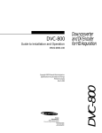
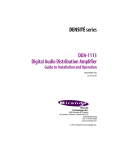
HDC-1801 HD Downconverter & DA Guide to Installation and Operation M760-9800-103 February 2010 (DENSITÉ) SERIES HDC-1801 FEATURES DESCRIPTION The HDC-1801 is an HD downconverter as well as a distribution amplifier. The HDC series cards are dual rate for hybrid HD/SD facilities. The DA section provides up to 4 HD re-clocked outputs, and the HD downconverter supports multiple formats of signals, such as 1080i, 720p, 23.98 psf. All Metadata (TC, CC) and audio (2 groups) are processed in HD and SD. When SD is set at the input, the card offers ARC functionality with five presets. The SDI output can add on-screen display of Time code and input format as well as graticules and markers. This card operates with the MSB-1121 Monitoring Switching Bridge which allows the output of any module in the Densité frame to be monitored. Multiple MSB equipped frames may be cascaded to form a large monitoring bus, eliminating the need for dedicated monitoring routers FUNCTIONAL BLOCK DIAGRAM 1 2 HD/SD 3 SDI OUT 4 Reclocked DA Outputs Thumbnail HD/SD SDI IN Demux Down-convert & ARC SD MUX SDI Out MSB ANC (CC, TC) Process & Delay • HD/SD dual rate auto-detect input with up to 4 re-clocked outputs • Up to 3 SDI down-converted/ARC outputs • Two AES digital audio outputs • HD 10-bit down-converter processing • SD 10-bit ARC process with 5 presets • Time Code processing and delay • Selectable OSD for input format and SD output Time Code • Selectable Graticules and Markers insertion • Audio de-embedding/embedding of 2 groups in HD to SD (option) • VBI by-pass in SD to SD mode • Thumbnails and audio level meters (ALM) (with audio option) • Signal presence detection and remote reporting • Provides output to Monitoring Switching Bridge option (MSB-1121) 1 2 SDI OUT 3 Burn-in generator ALM Audio Process & Delay Group select AES Out L AES OUT R Audio option HDC-1801 Page 1 of 17 HDC-1801 HD Downconverter & DA with Analog Monitoring Output Guide to Installation and Operation SPECIFICATIONS INPUT Signal: Formats: SMPTE 292M (1.485, 1.485/1.001 Gbps) SMPTE 259M (143, 177, 270 & 360 Mbps) HD: 1080i 59.94, 50, 23.98psf, 720p 59.94, 50 SD: 525, 625 Cable Length HD: 110 m (350’) for Belden 1694A SD: 250 m (850’) Return Loss: > 15 dB up to 1.5 GHz DA OUTPUTS (4) Signal: SMPTE 292M (1.485,1.485/1.001 Gbps) SMPTE 259M (143, 177, 270 & 360 Mbps) Return loss: > 15 dB up to 1.5 GHz Added Jitter: < 0.2 UI p-p (wideband) 10 bits Processing delay: < 6 ns SMPTE 259M-C (270 Mbps) Return Loss: > 15 dB up to 270 MHz Added Jitter: <0.2 UI p-p (WIDEBAND) (with HDC-1801-75-DRP rear panel) Signal: AES-3id (SMPTE 276M) Level: 1.0 Vp-p Max level: + 24 dBu / 600 Ω Impedance: 75 Ω unbalanced Jitter: 0.008 UI Peak (50Hz to 100 KHz) Signal path: 10 bits Processing delay: HD input to HD SDI output: HD input to SD SDI outputs: Frame rate of 59.94Hz Frame rate of 50Hz Frame rate of 23.98Hz SDI OUTPUTS Signal (3): (with HDC-1801-110-DRP rear panel) Signal: AES-3 Level: 3.8 Vp-p Max level: + 24 dBu / 600 Ω Impedance: 110 Ω Jitter: 0.008 UI Peak (50Hz to 100 KHz) DIGITAL VIDEO PROCESSING PERFORMANCE DA PROCESSING PERFORMANCE Signal path: AES OUTPUTS Power: < 2uS 34ms 41ms 83ms 10 W Select Status SDA-1101 - SD DIGITAL VIDEO D HDC-1801 Select button Status LED Page 2 of 17 HDC-1801 Rear panel modules HDC-1801 HD Downconverter & DA with Analog Monitoring Output Guide to Installation and Operation UNPACKING Make sure the following items have been shipped with your HDC-1801. If any of the following items are missing, contact your distributor or Miranda Technologies Inc. * HDC-1801 HD Downconverter & DA w/ audio mon. * HDC-1801-DRP or HDC-1801-A-DRP rear panel Detailed instructions for installing cards and their associated rear panels in the Densité frame are given in the Densité Frame manual. Rear panel installation Note that the HDC-1801 has ten input & output connectors, and making these available at the rear of the frame requires a double-width rear panel. When a double–width rear panel is used, the module must be installed in the right-most of the two slots associated with the rear panel in order to mate with the rear-panel connectors. If it is placed in the wrong slot, the front panel LED will flash red. Move the card to other slot for correct operation. No damage will result to the card should this occur. INSTALLATION The HDC-1801 must be mounted in a DENSITÉ frame. The installation includes both the HDC-1801 module, and the rear panel module. It is not necessary to switch off the frame’s power when installing or removing the HDC-1801. reporting for this card on the DENSITÉ frame’s serial and GPI interfaces. OPERATION Overview Status Indicator The HDC-1801 is equipped with an on-board LED status indicator, mounted on the front edge of the card so as to be visible from the front of the card frame, even when the frame door is closed. The functionality of this status monitor is described below.The DENSITÉ frame incorporates a central controller card, located in the center of the frame, which is equipped with an LCD display. The card handles error reporting and remote control for all cards installed in the frame. The display shows the error status of any card in the frame whose SELECT button has been pushed. REPORT SERIAL GPI The HDC-1801 is also equipped with the remote reporting and control capabilities of the DENSITÉ series. Fault reporting is carried out on a frame-wide basis. There is no individual rear-panel access to the fault and status reporting port of the HDC-1801. Interfacing to the outside world is handled by the frame’s controller card. The fault reporting protocol is standardized across the DENSITÉ series of modules. Status Monitor LED The status monitor LED is located on the front cardedge of the HDC-1801 module, and is visible through the front access door of the DENSITÉ frame. This multi-color LED indicates module status by color, and by flashing/steady illumination, according to the following chart. The chart also indicates fault No errors No input signal or input signal error DA only mode No audio group 1 No audio group 2 No audio group 3 No audio group 4 No CC (HD/525) or WSS (625) No timecode Test pattern COLOR (F=flashing) G Y R FR : Factory default. NOTE: A “Flashing Yellow” Status LED indicates that the SELECT button on the front panel has been pushed, and the card is being accessed by the controller. The LED color assignments for the various error conditions can be reconfigured by the user. HDC-1801 Page 3 of 17 HDC-1801 HD Downconverter & DA with Analog Monitoring Output Guide to Installation and Operation The HDC-1801 has operating parameters which may be adjusted using menus operated at the controller card interface. After pressing the SELECT button on the HDC-1801 card, use the keys on the local control panel to step through the menu and adjust these parameters. Local User Interface Push the SELECT button on the front edge of the HDC-1801 to see a report of the current error status on the DENSITÉ frame’s controller card display. The display will cycle through these four status messages: STATUS The use of the local control panel is described in more detail in the controller card manual. NO REAR; NO SIGNAL; DA ONLY; 720p50; 720p59.94; 1080p23.98sF; 1080i50; 1080i59.94; 625; 525 The menus, including the parameters which can be adjusted, and the options which are available, are shown in the following figure. NO REAR; NO AUDIO GROUP; GROUP:1234 NO REAR; NO TIMECODE; TIMECODE PRESENT NO REAR; NO CC/ WSS; CC/ WSS PRESENT For a complete explanation of the parameters and values shown in the menus, see the section on the iControl Interface for the HDC-1801 which follows the menu chart. The STATUS LED will revert to its normal state upon a second push of the button, or after a short delay otherwise. HDC-1801 Menus NO REAR; NO SIGNAL; DA ONLY; 720p50; 720p59.94; 1080p23.98sF; 1080i50; 1080i59.94; 625; 525 STATUS** NO REAR; NO AUDIO GROUP; GROUP:1234 [only on cards with Audio option] NO REAR; NO TIMECODE; TIMECODE PRESENT NO REAR; NO CC/ WSS; CC/ WSS PRESENT USER PRESETS** ARC** PRESET LOAD [USER1/ USER2/ USER3/ USER4/ USER5] SAVE [USER1/ USER2/ USER3/ USER4/ USER5] if IN = OUT SD ratios [BYPASS] if IN ≠ OUT and OUT = 4:3 [ANAMORPHIC/ LETTER BOX/ HORIZONTAL CROP/ 14:9] if IN ≠ OUT and OUT = 16:9 [ANAMORPHIC/ SIDE PANEL/ VERTICAL CROP/ 14:9] if HD in and OUT = 16:9 [BYPASS] if HD in and OUT = 4:3 [ANAMORPHIC/ LETTER BOX/ HORIZONTAL CROP/ 14:9] INPUT ASPECT [4:3 / 16:9] Available with SD input only, always 16:9 in HD OUTPUT ASPECT [4:3 / 16:9] In SD, the default value is 4:3; in HD, the default value is 16:9 (continued) Page 4 of 17 HDC-1801 HDC-1801 HD Downconverter & DA with Analog Monitoring Output Guide to Installation and Operation DE-EMBED [GROUP 1&2 / GROUP 3&4] Available only on HDC-1801 with the audio option AES OUT if Group 1&2 if Group 1&2 OSD/SAFETY ZONE** SDI OUT AUDIO** ANALOG VIDEO OUT SAFETY ZONE CC/ WSS** [GROUP 1 / GROUP 2] [GROUP 3 / GROUP 4] TIME CODE [OFF / ON] INPUT FORMAT [OFF / TEMP 3S / ON] SAFETY ZONE [OFF / ON] TIME CODE [OFF / ON] INPUT FORMAT [OFF/ TEMP 3S / ON] SAFETY ZONE [OFF / ON] GRATICULE [OFF/ 80% / 90% / 92.5% / 95% / 4:3] MARKER RATIO [OFF/ 4:3 / 13:9 / 14:9 / FILM] [OFF / ON] Not available for 720p50 or 1080i50 input [OFF, 10, 11, …, 14, …, 19, 20] HD in to 525 output, stop at line 18 when DUPLICATE is ON TC** LINE INSERT [OFF, 7, 8, 9, …, 19, 20, 21, 22] HD in for 625 output, stop at line 20 when DUPLICATE is ON [BYPASS] for SD in [OFF / ON] for HD in DUPLICATE [BYPASS] for SD in 720p TRACKING INPUT ERROR** TEST** [OFF / ON] when HD in is 720p50 or 720p59.94 [NOT AVAILABLE] for other input formats [KILL / BLACK] VIDEO [OFF / ON] AUDIO [OFF / ON] Available only on card with audio option (continued) HDC-1801 Page 5 of 17 HDC-1801 HD Downconverter & DA with Analog Monitoring Output Guide to Installation and Operation CONFIG ALARM** NO SIGNAL DA ONLY MODE NO AUDIO GRP 1 Available only on card with Audio option (repeat for Audio Groups 2, 3 and 4) NO CC/ WSS (available for all input formats except 625) NO TC TEST VERSION OPTION** ALARM LEVEL [GREEN / YELLOW / RED / FLASH RED] ALARM REPORT [NONE / GPI] ALARM LEVEL [GREEN / YELLOW / RED / FLASH RED] ALARM REPORT [NONE / GPI] ALARM LEVEL [GREEN / YELLOW / RED / FLASH RED] ALARM REPORT [NONE / GPI] ALARM LEVEL [GREEN / YELLOW / RED / FLASH RED] ALARM REPORT [NONE / GPI] ALARM LEVEL [GREEN / YELLOW / RED / FLASH RED] ALARM REPORT [NONE / GPI] ALARM LEVEL [GREEN / YELLOW / RED / FLASH RED] ALARM REPORT [NONE / GPI] HDC-1801:XXX.XXX AUDIO PROC OFF/ON [XXXXXXXX]** (32 bit value in hexadecimal format for each option license) LINE SCOPE OFF/ON FACTORY DEFAULT** [YYYYYYYY]** RESTORE Returns all parameter values to those underlined in this chart NOTES FOR THE MENU: [ ] List of parameter values to select ** Press Select pushbutton to activate selection. Underlined values are Factory Default values Page 6 of 17 HDC-1801 HDC-1801 HD Downconverter & DA with Analog Monitoring Output Guide to Installation and Operation for information about setting up and operating iControl. iCONTROL INTERFACE In addition to local control through the menus, the HDC-1801 can be remotely controlled using Miranda’s iControl system. This manual describes the control panels associated with the HDC-1801 and their use. Please consult the iControl User’s Guide In iControl Navigator, double-click on the HDC-1801 icon to open the control panel. Click on an entry in the left-hand pane to open the associated control panel. The available controls are described in the following section. ARC (Aspect Ratio) This panel configures the details of aspect ratio conversion between input and output. The two preview windows model the ARC function. • The INPUT window shows the portion of the input that will be sent to the output. The complete input would be a full white screen with a full-height green circle in the center. Any part of the input that will be cropped is shown in black. The circular shape is the full height of the original input. • The OUTPUT window shows the actual format of the video output from the HDC-1801. The white portion with the green shape corresponds to the contents of the INPUT window. Grey areas surrounding it are inserted into the output by the HDC-1801. If anamorphic processing has been applied, the green shape shows the type of distortion that will be introduced. Select input and output aspect ratios using the pulldown in the upper corner of the window. Then select the desired ARC processing using the radio buttons in the Aspect Ratio box beneath the windows. The contents of the box change depending on the aspect ratios selected. The box is disabled when the input and output aspect ratios are the same. The following conversions are possible: 4:3 Æ 16:9 Anamorphic • The input is stretched horizontally to fill the wider output screen. The green circle is distorted into an oval, showing how shapes in the video image will be distorted. 4:3 Æ 16:9 Side Panel 25% • The input image is placed into the centre of the wider output screen, and the remaining space on each side is filled with black. HDC-1801 Page 7 of 17 HDC-1801 HD Downconverter & DA with Analog Monitoring Output Guide to Installation and Operation 4:3 Æ 16:9 Crop 25% • The top and bottom of the input image are cut off so that its cropped aspect ratio is 16:9. The cropped input is then symmetrically resized to fill the entire output screen. 4:3 Æ 16:9 14:9 • The top and bottom of the input image are cut off so that its cropped aspect ratio is 14:9. The cropped input is then symmetrically resized to the full height of the output screen. Because its aspect ratio is 14:9, the resized picture does not completely fill the width of the screen. The remaining space on each side is filled with black. • This option is approximately midway between the Side Panel and Crop options. 16:9 Æ 4:3 Anamorphic • The input is squeezed horizontally to fill the narrower output screen. The green circle is distorted into an oval, showing how shapes in the video image will be distorted. 16:9 Æ 4:3 Letter Box 25% • The input image is symmetrically resized to fit into the width of the narrower output screen and the remaining space on top and bottom is filled with black. 16:9 Æ 4:3 Crop 25% • The sides of the input image are cropped so that its aspect ratio is 4:3. The cropped input is then placed to fill up the output screen. 16:9 Æ 4:3 14:9 • The sides of the input image are cut off so that its cropped aspect ratio is 14:9. The cropped input is then symmetrically resized to the full width of the output screen. Because its aspect ratio is 14:9, the resized picture does not completely fill the height of the screen. The remaining space on top and bottom is filled with black. • This option is approximately midway between the Letter Box and Crop options. Page 8 of 17 HDC-1801 HDC-1801 HD Downconverter & DA with Analog Monitoring Output Guide to Installation and Operation TC / CC / WSS The current ARC status is shown in the two preview windows at the top of the panel. Click on the ARC (Aspect Ratio) option to make changes Time Code Time Code Presence: the icon is Green if time code is currently being detected in the input signal, and grey if not. Insertion: use the pulldown list to select whether time code will be inserted in the output. Insert Line: use the pull-down list to select the line into which time code will be inserted when insertion in ON. Duplicate: from the pulldown list, select whether Duplication is ON or OFF. DUPLICATION inserts a second copy of the time code two lines after the Insert Line, when possible. For example, if the Insert Line is 16 and duplication is ON, lines 16 and 18 will both contain the same time code. 720p Tracking: from the pulldown list, select whether 720p tracking is ON or OFF (available only when input is 720p50 or 720p59.94). 720p tracking is a way to lock the field sequence of the downconverted interlaced video output with the input time code. Since there is no “field” in a progressive format such as 720p, enabling this option is the only way to ensure that the output video will follow a specific field sequence. Note that a discontinuity in the input time code sequence can cause a break in the output video signal, so this option should only be used when tracking a field sequence is a major issue. CC / WSS CC / WSS Presence: the icon is Green if Closed Captioning (for 59.94 Hz signals) or Wide Screen Signaling (for 625 line 50 Hz signals) is currently being detected in the input signal, and grey if not. CC / WSS Enable: click in the checkbox to enable the insertion of the CC / WSS information into the HDC-1801 output. HDC-1801 Page 9 of 17 HDC-1801 HD Downconverter & DA with Analog Monitoring Output Guide to Installation and Operation Audio [This panel is only available if the Audio Option has been activated. See the Options panel] The current ARC status is shown in the two preview windows at the top of the panel. Click on the ARC (Aspect Ratio) option to make changes. Group Detected: If an embedded audio group is detected on the input signal, its icon is green. Audio De-embed: Select whether to de-embed either Groups 1 & 2, or Groups 3 & 4. AES Out: Select which of the two AES audio streams will be XXXX output of the HDC-1801. OSD / Safety Zone The current ARC status is shown in the two preview windows at the top of the panel. Click on the ARC (Aspect Ratio) option to make changes. SDI Output Time Code: Click on the checkbox to display time code on the SDI output. Safety Zone: Click on the checkbox to display the Safety Zone graticule and marker on the SDI output. Input Format: Select whether to display the input format in the SDI output, and whether it should be displayed all the time (ON) or just for three seconds when the format changes (TEMP 3 sec). Safety Zone Graticule: From the pull-down list, choose the size of the Safety Zone to be displayed on the down converted output. Those listed in percentage maintain the aspect ratio of the input. The 4:3 graticule is 90% of a 4:3 screen, and is useful when shooting 16:9 which could be distributed in 4:3. Page 10 of 17 HDC-1801 HDC-1801 HD Downconverter & DA with Analog Monitoring Output Guide to Installation and Operation Graticules are rectangles of the selected size, applied to the input and processed through the downconversion. The appearance of the graticule on the output shows the effect of any cropping and anamorphic distortion that has been applied. Marker: From the pull-down list, select the aspect ratio of the marker that will be shown at the output. Film refers to an aspect ratio of 1.85:1, typical of 35mm film footage. . Markers are pairs of lines that cross the screen to show the boundaries corresponding to the selected aspect ratio (i.e. 100%). They are applied to the input and processed through the downconversion. The appearance of the marker on the output shows the effect of any cropping and anamorphic distortion that has been applied. Streaming Enable: Click on the Video radio button enable the Video streaming function of the HDC-1801. Size: Select the size of image to be sent by the streaming encoder Player: Click on the Thumbnail radio button to enable the display of video thumbnails on this control panel. Quality and Refresh Rate: • Use the left-hand pulldown to select the video quality to be sent by the streaming encoder. The choices are Poor, Normal and HiQ (e.g. high quality). • Use the right-hand pulldown to select the refresh rate for the transmitted thumbnails. The choices are Fast, 1 sec, 2 sec, … 10 sec. Streaming Priority Control: Click the Take control from Slot [##] checkbox to force the Densité Controller for this frame to assign more bandwidth for this card’s streaming output. Only one card in the frame can use this feature. It has no effect unless you have selected Fast for the refresh rate. The actual slot number of this card, as shown in the window title bar, will appear when the checkbox is ticked. HDC-1801 Page 11 of 17 HDC-1801 HD Downconverter & DA with Analog Monitoring Output Guide to Installation and Operation RALM The Remote Audio Level Meter (RALM) displays the sampled audio level data received from the HDC1801 card. RALM Connections tab CH 1&2: Click RALM to connect the left-hand meter to AES channels 1 and 2. CH 3&4: Click RALM to connect the right-hand meter to AES channels 3 and 4. An unconnected meter is dimmed. Reset Counter: Click the Reset Counter button to reset the overload counter for the indicated channels. The counter’s current value appears above the meter scale. Meter Ballistics Config tab Type – select a type of meter from the pull-down list Upper Zone Limits – select the crossover level between the upper and middle zones of the meter (the range of values shown in the pull-down list depends on the type of meter selected) Lower Zone Limits – select the crossover level between the middle and lower zones of the meter (the range of values shown in the pull-down list depends on the type of meter selected) Color samples – the three samples show the current selected color for the upper, middle and lower zones of the meter. • Click on the color sample of a zone to open a color selection panel to choose a different color for that zone Overload Cursor – The overload cursor appears on the meter as an arrowhead in the meter scale. The two pulldown boxes set the position of the overload cursor on the left and right meters. If the audio level on that channel goes above the cursor, the Overload Counter at the top of the meter is incremented. RALM Remote Control Click in a checkbox to connect the meter display on this panel to the indicated channels on the HDC1801 card. Speed – select the meter refresh rate from the pulldown list (fast, medium or slow) Page 12 of 17 HDC-1801 HDC-1801 HD Downconverter & DA with Analog Monitoring Output Guide to Installation and Operation Input Error The current ARC status is shown in the two preview windows at the top of the panel. Click on the ARC (Aspect Ratio) option to make changes. Input Error Select the behavior of the SDI output in the event of an error in the input signal. • If the KILL radio button is selected, the SDI output will be disconnected in case of an input error. The connector will carry no signal. • If the BLACK button is selected, the SDI output connector will carry a signal with BLACK in the active picture area. Test The current ARC status is shown in the two preview windows at the top of the panel. Click on the ARC (Aspect Ratio) option to make changes. Video Click on the Color Bars (75%) checkbox to place a 75% color bar signal on the video output. Audio Click on the Tone checkbox to place audio test tones on the audio outputs (if the Audio option has been enabled). The test tone is a 1 KHz sine wave: • left channel – pulsed 3 seconds ON, 250 ms OFF • right channel – steady tone The test tone will be placed on the AES and embedded outputs. The input groups that were not disembedded are blanked. HDC-1801 Page 13 of 17 HDC-1801 HD Downconverter & DA with Analog Monitoring Output Guide to Installation and Operation Options Audio Option Activate the Audio option on the HDC-1801 card by entering the activation key into the Enter Key data box, and clicking the Enable Option button. The current status of the Audio option is shown in the status box below the Enter Key data box. See the text message at the top of the tab for information about purchasing the Audio option and obtaining the activation key. IP Scope Option The IP Scope option adds a line scope output to the HDC-1801. This output can be viewed on a standard PC using the iControl Streaming Player, which shows waveform monitor and vectorscope displays. Activate the IP Scope option on the HDC-1801 card by entering the activation key into the Enter Key data box, and clicking the Enable Option button. The current status of the IP Scope option is shown in the status box below the Enter Key data box. See the text message at the top of the tab for information about purchasing the IP Scope option and obtaining the activation key. Waveform Monitor and Vectorscope Enable: Click on the checkbox to turn the IP Scope output ON. Line: Use the slider or type in the data box to select the video line that will be used by the line scope. The current selection is shown in the data box. Refresh Rate: choose how often the line scope display will be refreshed. Options are 1 sec to 10 sec, and Fast. Page 14 of 17 HDC-1801 HDC-1801 HD Downconverter & DA with Analog Monitoring Output Guide to Installation and Operation Info The Info panel provides information about the HDC1801, and provides some data entry options. Label: Type a name for this device into the data entry box (e.g. Studio 46 Video FX output) Short Label: Type a shorter version of the name (e.g. ST46VFX) Source ID: Type text identifying the video input to the HDC-1801, if desired. Comments: Type any desired text into this box Details…: click on this button to get information about the manufacturing process and panel version. Advanced…: Click on this button to get the Miranda Long ID of this HDC-1801. The Miranda Long ID is the address of this device in the iControl network, and is required by some devices, e.g. Kaleido, to access it. Remote System Administration…: Click on this button to open the Joining Locators: HDC-1801 data entry box. Factory Click on the Load Factory button to restore all parameter settings on the HDC-1801 to their factory default values. The Menu shown in this manual lists all possible values for these parameters. The Factory Default values are underlined in the Menu. HDC-1801 Page 15 of 17 HDC-1801 HD Downconverter & DA with Analog Monitoring Output Guide to Installation and Operation User Presets The User Presets are a set of five registers, each of which can store a complete set of parameter settings. The User preset registers are accessed from the User Presets controls at the bottom left of the control panel. Select any one of the five presets using the pulldown list. The name of the currently-selected User Preset is shown on the on the pulldown icon (e.g. User1, User2,… User5) Click Load to load the contents of the selected User Preset into the HDC-1801. All parameter settings and values will be replaced by the contents of the selected User Preset. Click Save to store the current parameter settings and values from the HDC-1801 into the selected User Preset. The existing contents of the preset will be overwritten. Error/Warning Configuration In iControl Navigator, right-click on the HDC-1801 icon, and select the Error/Warning Configuration option from the pop-up menu. The Log Config panel opens. For each of the nine Conditions shown in the panel, select: Detection: the checkbox to the immediate right of the condition name enables detection of the condition. If it is unchecked, the other options are disabled and grayed-out in this panel Condition LEVEL: From the pulldown box, assign a level of severity to this condition. The choices are: • YELLOW = warning • RED = error Report GUI: a check in this box enables an error report from this card on the Densité frame’s GUI output. Page 16 of 17 HDC-1801 HDC-1801 HD Downconverter & DA with Analog Monitoring Output Guide to Installation and Operation COMPLIANCE Electromagnetic Compatibility This equipment complies with the requirements of: FCC Part 15 Subpart B (2005) Class A, Conducted emissions FCC Part 15 Subpart B (2005) Class A, Radiated emissions EN 55022 (1998) Class A, Radiated emissions. EN 55022 (1998) Class A, Conducted emissions EN 61000-3-2 (2000) Harmonic current emission limits EN 61000-3-3 (1995/A1-2001) Voltage fluctuation and flicker limitations EN 61000-4-2 (1995/A1-1998/A2-2001) Electrostatic discharge immunity EN 61000-4-3 (1996/A1-1998) Radiated electromagnetic field immunity – radio frequencies EN 61000-4-4 (1995/A1&A2-2001) Electrical fast transient immunity EN 61000-4-5 (1995/A1-2001) Surge immunity EN 61000-4-6 (1996/A1-2001) Conducted immunity EN 61000-4-11 (1994/A1-2001) Voltage dips, short interruptions and voltage variation immunity ENV50204 (1995) Radiated electromagnetic field immunity – 900 MHz pulsed How to contact us: For technical assistance, please contact the Miranda Technical support centre nearest you: Americas Telephone: +1-800-224-7882 e-mail: [email protected] Asia Telephone: +852-2539-6987 e-mail: [email protected] Europe, Middle East, Africa, UK Telephone: +44 (0) 1491 820222 e-mail: [email protected] China Telephone: +86-10-5873-1814 e-mail: [email protected] France (only) Telephone: +33 (0) 1 55 86 87 88 e-mail: [email protected] Visit our web site at www.miranda.com HDC-1801 Page 17 of 17