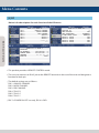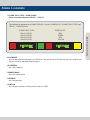
1
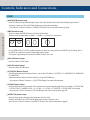
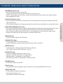
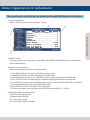
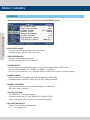
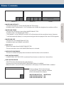
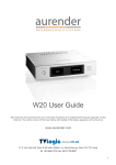
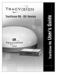
Multi Format
AMOLED Monitors
Operation Manual
LEM Series
LEM-150
multi
Contents
............................................................................................. 4
Caution ........................................................................................... 7
Features .................................................... 9
Controls, Indicators and Connections .......................................................... 15
Menu Organization & Adjustment Menu Contents ..................................................................................
16
Other Functions .................................................................................
39
............................... 43
DVI ANALOG/DVI DIGITAL / HDMI Support Resolution ........................................................................ 44
Product Specifications
.................................................................................. 45
Product Lineup
Optional Accessories ..........................................................................
47
FCC (Federal Communications Commission)
This equipment has been tested and found to comply with the limits for class A digital device, pursuant to part 15 of the
FCC Rules. These limits are designed to provide reasonable protection against harmful interface when the equipment
is operated in a commercial environment.
This equipment generates, uses and can radiate radio frequency energy and if not installed and used in accordance
with the instruction manual, may cause harmful interference to radio communications. Operation of this equipment
in a residential to correct the interference at his own expense
CAUTION: Change or modifications not expressly approved by the manufacturer responsible for compliance could
void the user’s authority to operate the equipment.
Disposal of Old Electrical & Electronic Equipment
(Applicable in the European Union and other European countries with separate collection systems)
This symbol on the product or on its packing indicates that this product shall not be treated as household waste.
Instead it shall be handed over to the applicable collection point for the recycling of electrical and electronic
equipment. By ensuring this product is disposed of correctly, you will help prevent potential negative consequence
for the environment and human health, which could otherwise be caused by inappropriate waste handling of this
product. The recycling of materials will help to conserve natural resources.
Caution
◦ Power Requirements
- AC 100 ~ 240V
- DC 12V/24V
◦ All operating instructions must be read and understood before the product is operated.
◦ These safety and operating instructions must be kept in safe place for future reference.
◦ Do not use attachments not recommended by the manufacturer. Use of inadequate attachments
Multi
Format
LCD
Monitor
Multi
Format
LCD
Monitor
can result in accidents.
◦ This product must be operated on a power source specified on the specification label.
If you are not sure of the type of power supply used in your location, consult your dealer or local
power company.
◦ The power cords must be routed properly to prevent stepping on them or objects from resting on
them. Check the cords at the plugs and product.
◦ Do not overload AC outlets or extension cords. Overloading can cause fire or electric shock.
◦ Never insert an object into the product through vents or openings. High voltage flows in the
product and inserting an object can cause electric shock and/or short internal parts.
For the same reason, do not spill water or liquid on the product.
◦ Do not attempt to service the product yourself. Removing covers can expose you to high voltage
and other dangerous conditions. Utilize a qualified electronics service specialist for all repairs.
◦ If any of the following conditions occurs, unplug the power cord from the AC outlet and request a
qualified service person to perform repairs.
a. When the power cord or plug in damaged.
b. When a liquid was spilled on the product or when objects have fallen into the product.
c. When the product has been exposed to rain or water.
d. When the product does not operate properly as described in the operating instructions.
Do not touch the controls other than those described in the operating instructions.
Improper adjustment of controls not described in the instructions can cause damage,
which often requires extensive adjustment work by a qualified technician.
e. When the product has been dropped or damaged.
f . When the product displays an abnormal condition. Any noticeable abnormality
in the product indicates that the product needs servicing.
Caution
◦ In case the product needs service, consult an authorized TVLogic Reseller.
◦ Unplug the power cord from the AC outlet before cleaning the product. Use a damp cloth to clean
the product. Do not use liquid cleaners or aerosol cleaners.
◦ Keep the product away from direct Sun light.
unstable base can cause the product to fall, resulting in serious personal injuries as well as damage
to the product. Use only a cart, stand, tripod, bracket or table recommended by the manufacturer
or sold with the product. When mounting the product on a wall, be sure to follow the manufacturer's
instruction. Use only the mounting hardware recommended by the manufacturer.
◦ The vents and other openings in the cabinet are designed for ventilation. Do not cover or block
these vents and openings since insufficient ventilation can cause overheating and/or shorten the
life of the product. Do not place the product in an enclosed place such as a bookcase or rack, unless
proper ventilation is provided or the manufacturer's instructions are followed.
◦ The OLED panel used in this product is made of glass. Therefore, it can break when the product is
dropped or exposed to impact.
◦ Keep the product away from heat sources such as radiators, heaters, stoves and other
heat generating products (including amplifiers).
◦ The mains plug, as a disconnection device, shall remain readily accessible by the user.
◦ Use the this unit shall be connected to a mains socket outlet with a protective earthing connection.
◦ The product should not be exposed to liquid of any kind. In addition, no objects filled with liquid
should be placed on the apparatus.
◦ Make sure it has more than 10 cm clearance all around the unit.
Multi Format LCD Monitor ◦ Do not place the product on an unstable cart, stand, tripod or table. Placing the product on an
Caution
WARNING!!
# Warning for the image sticking!!
◦ Persistent image sticking can result from the exposure of the screen to certain types of static element
within the displayed picture and it can be permanent or temporary.
Image sticking of the screen caused by below will not be covered by the warranty.
Multi
Format
LCD
Monitor
Multi
Format
LCD
Monitor
Please avoid watching the static image (30 minutes) or image with fixed logos. Static images can be
remained permanently on the screen.
* Static images : Logos, captions, on screen menu or computer screen. Also, long term use of 4:3 screen
can also result burn in of the screen boundary area. (This condition is similar to the third-party products
and not subject to exchange or refund.)
To prevent the image sticking, this product darkens the screen after watching static image for set
period of time in the menu.
Screen goes back to normal brightness when the unit is operated again or receives moving image.
Features
LEM SERIES MONITORS CONTAIN THE FOLLOWING FEATURES AND ADVANTAGES :
◦ 15” 1366 x 768 OLED (Organic Light Emitting Diode) display.
◦ 100,000:1 contrast ratio.
◦ Ultra-wide 180° viewing angle.
◦ Compatible with varied SDI signals
- The product is compatible with varied SDI signals - 408i, 576i, 1080i, 1080p, 1080psf
◦ Compatible with varied analog signals
- The product is compatible with varied analog signals – Composite, S-Video, Component, RGB and etc.
(LEM-150 supports NTSC, NTSC-J, PAL, PAL-M, SECAM broadcast standards)
◦ All-in-one type system
- Slim and all-in-one type monitor that requires no other accessories and optimized for space utilization.
◦ Wide Screen Support
- This product supports native 16:9 aspect ratio.
◦ AC/DC compatible
- This product may be powered by a normal AC source but is also compatible with 12/24V DC.
◦ Remote control function
- Remote is controlled simply with a cable connection without any additional peripheral equipment
attached to the unit.
◦ RS422/UMD feature support
- This product supports protocols provided by TVLogic or a TSL protocol.
◦ RS232 support
- Supports firmware updates & auto-calibration.
◦ Ethernet & USB support
- Supports ethernet and USB connection for program download.
◦ DVI/HDMI(HDCP) input support
- DVI/HDMI(HDCP) input is available without any other accessory.
Multi Format LCD Monitor ◦ Near-instantaneous signal to image response for lag-free video. (2.8ms)
Features
◦ Dual link support
- Supports Dual link YCbCr/RGB 4:4:4 and YCbCr 4:2:2 formats.
◦ 3G support
- Supports 3G A/B formats.
◦ Additional features
- Loop-through out (SDI), VESA Mounting, user interface and rack-mountable.
◦ Active Format Description (AFD)
Multi
Format
LCD
Monitor
Multi
Format
LCD
Monitor
- Supports meta-data flags to set aspect ratio and active picture characteristics.
Controls, Indicators and Connections
LEM-150 : FRONT
APERTURE
BRIGHT
CHROMA
CONTRAST
VOLUME
INPUT STATUS
POWER
ANALOG
SDI-A
SDI-B
PBP
F1
F2
F3
ENTER
DOWN/UP
MENU
BLUE ONLY/MONO
H/V DELAY
MARKER
SCAN
LEM-150 : REAR
HDMI
RS232
CVBS1/Y/G/S-Y
CVBS2/Pb/B
CVBS3/Pr/R/S-C
DVI-I
SDI IN-A
SDI OUT-A
SDI IN-B
SDI OUT-B
USB
ETHERNET
AC IN
POWER S/W
DC IN
AUDIO OUT
AUDIO IN
REMOTE
RS422 OUT
RS422 IN
Multi Format LCD Monitor ΅ͲͽͽΊ
Controls, Indicators and Connections
FRONT
◦ [ANALOG] Button/Lamp
- Used to select the desired Analog input. Press the button to activate the analog input menuselection, then use UP and DOWN button to select desired input.
* See section “Other Functions [1]ANALOG Button” for more information (pg 39).
Multi
Format
LCD
Monitor
1010
Multi
Format
LCD
Monitor
◦ [PBP] Button/Lamp
- Used to select the PBP (Picture-by-Picture) function.
- Selects order of operation: mode 1 -> mode 2 -> mode 3 in sequence.
MODE1
MODE2
MODE 3
- Use [SCREEN SEL] (F1,F2,F3 modes) button to select a screen and use SOURCE key (Analog, SDI-A
or SDI-B) to switch the screen to desired input signal.
- The input signal lamp for each of the PBP screens turns on.
◦ [SDI-A] Button/Lamp
- Used to select SDI-A input.
◦ [SDI-B] Button/Lamp
- Used to select SDI-B input.
◦ [F1][F2][F3] Button/Lamp
- Used to activate the function which is set in the OSD Menu “SYSTEM-> F1 MAPPING/F2 MAPPING/
F3 MAPPING” .
- After activation, adjust the function by using UP/DOWN key.
* See section “Menu Contents -> [9]SYSTEM Page” for more information.
◦ [SCAN] Button/Lamp
- Used to change the scan mode. Press the button to activate through the scan modes : OVER SCAN
-> ZERO SCAN -> UNDER SCAN -> 2:1 SCAN -> 1:1 SCAN -> FIT WIDTH -> ZOOM (PBP 16:9 mode)
* See section “Other Functions [2]SCAN Button” for more information (pg 40).
◦ [ASPECT] Button/Lamp
- Used to change the display ratio between 4:3 and 16:9.
- Display ratio locks to 16:9 if the display ratio of input signal is 16:9.
- See section “Other Functions [3] ASPECT Button” for more information (pg43).
Controls, Indicators and Connections
◦ [MARKER] Button/Lamp
- Used to activate/deactivate the marker.
- The type of marker at work may be selected on the main menu.
- If AFD is selected on the main menu, marker automatically activates when input signal contains
the embedded AFD data.
◦ [BLUE ONLY/MONO] Button/Lamp
- Used to activate MONO mode or remove red and green from the input signal and display the screen
only under a blue signal. Not available in RGB, DVI ANALOG, DVI DIGITAL and HDMI modes.
- Press the button again to activate the Focus Assist mode which will indicate the edges of the
display in the color that can be selected in the WAVEFORM menu.
◦ [MENU] Button
- Used to activate/ deactivate OSD Menu.
◦ [DOWN]/[UP] Button
- Used to select Main menu and submenu.
- Use UP/DOWN keys to select and proceed through various functions.
◦ [ENTER] Button
- Used to enter to submenu and see the feature selected .
- See “Other Functions[2]SCAN Button” (pg. 35).
◦ [OPERATE] Lamp
- Indicates condition and power status of unit.
- Light turns off when the power is disconnected.
- Standby mode is indicated by a red LED light.
- Normal (active) mode is indicated by a Green LED light.
◦ [POWER] Button
- Used to turn power on and off.
◦ [TALLY] Lamp
- Tally lamp that can be toggled in green, yellow or red using the REMOTE(RJ-45) port.
◦ [APERTURE] knob
- Used to adjust the picture sharpness.
- Control value range : 0 ~ 25
- Unavailable in DVI ANALOG Mode.
Multi Format LCD Monitor 11
◦ [H/V DELAY] Button/Lamp
- Used to check horizontal sync and vertical sync simultaneously by moving the display to the left,
right up and down.
- In this mode, the brightness of image automatically increase for easy verification of synchronized signals.
Controls, Indicators and Connections
◦ [BRIGHT] knob
- Used to adjust the degree of brightness.
- Control value range : -100 ~ 100
Multi
Format
LCD
Monitor
1212
Multi
Format
LCD
Monitor
◦ [CHROMA] knob
- Used to adjust the saturation of the image.
- Control value range : -50 ~ 50
- Unavailable in RGB, DVI ANALOG, DVI DIGITAL and HDMI modes.
◦ [CONTRAST] knob
- Used to adjust the contrast.
- Control value range: -100 ~ 100
◦ [VOLUME] knob
- Used to adjust the volume for internal speaker and external output.
- Control value range : 0 ~ 30
Controls, Indicators and Connections
REAR
◦ [REMOTE] (RJ-45)
- Provides connection to control equipment for external monitor control.
- Features can be changed in the REMOTE(1/2) section of OSD menu.
◦ [RS422 IN/OUT] (RJ-45)
- Used to control the monitor with protocol provided by TVLogic, Image Video and TSL.
- Used to adjust color temperature by using color calibration tool.
◦ [DVI-I] (DVI-I)
- Signal input terminal for DVI ANALOG or DVI DIGITAL signal.
◦ [HDMI(HDCP)] (HDMI)
- Signal input terminal for HDMI signal.
◦ [CVBS1/Y/G/S-Y] (BNC)
- Signal input terminal used to feed the monitor COMPOSITE 1, S-VIDEO Y, COMPONENT Y and RGB
G signals.
◦ [CVSBS2/Pb/B] (BNC)
- Signal input terminal used to feed the monitor COMPOSITE 2, RGB B and COMPONENT Pb signals.
◦ [CVSBS3/Pr/R/S-C] (BNC)
- Signal input terminal used to feed the monitor COMPOSITE 3, S-VIDEO C, COMPONENT Pr and RGB
R signals.
◦ [SDI-IN A] (BNC)
- HD/SD SDI signal input terminal for SDI A.
◦ [SDI-OUT A] (BNC)
- HD/SD-SDI signal output terminal for SDI A signal.
◦ [SDI-IN B] (BNC)
- HD/SD SDI signal input terminal for SDI B.
◦ [SDI-OUT B] (BNC)
- HD/SD SDI signal output terminal for SDI B signal.
◦ [Audio in & out] (PHONE JACK)
- Select the left/right Audio disembedded signal output or HDMI input signal or external stereo
signal is output through the phone jack.
Multi Format LCD Monitor 13
◦ [RS232]
Controls, Indicators and Connections
◦ [Ethernet & USB]
- Ethernet and USB port for easy firmware updates.
◦ ~ AC IN
- 100 ~ 240V AC 50/60Hz
◦ DC 12V/24V IN
Multi
Format
LCD
Monitor
1414
Multi
Format
LCD
Monitor
- 12V/24V DC.
DC IN socket
1,2 : GND
3,4 : +12V/+24V
<Video input>
Video input connection method.
Connector
Composite
Component
S - Video
1
CVBS 1
Y
R
Y
2
CVBS 2
Pb
G
No Con.
3
CVBS 3
Pr
B
C
<Warning!!>
When using the product, make sure to connect the GND first before connecting the input signal line.
The unit may not operate properly if the input line is connected before the GND is connected.
Menu Organization & Adjustment
The product may be controlled and set system-wise through OSD displayed on the screen.
1) Menu Organization
Below is the organization of the product’s menu.
SDI A
③
④
LEM-150
1080/60i
PAGE I >> PAGE II
BRIGHT
0
CONTRAST
0
CHROMA
0
PHASE
0
APERTURE
0
NTSC SETUP
7.5IRE
VGA H POSITION
MIN
VGA V POSITION
MIN
①
2) Menu Control
You may control various functions using MENU, UP/DOWN and ENTER buttons on the bottom
front of the monitor.
3) Menu Control Sequence
Menu control sequence follows the order below :
1. Press MENU button to bring the OSD menu on the screen.
2. Display the desired sub menu with the UP/DOWN button.
3. After selecting a sub menu, press ENTER to select an item with the UP/DOWN button.
4. Press ENTER to select the desired item (verified by highlighted field text turning red).
5. Press ENTER to save the new value after adjusting the value with UP/DOWN button (Verified
by highlighted field returning to default black color).
6. Press MENU to remove OSD menu from the screen.
7. To view next page in the sub menu, press ENTER button at PAGE I >> PAGE II.
4) Main Menu Window Information
① Menu item and page info.
② Model name(LEM-150).
③ Current input signal.
④ Current input signal resolution.
Multi Format LCD Monitor 15
②
Menu Contents
[1] PICTURE
Multi
Format
LCD
Monitor
1616
Multi
Format
LCD
Monitor
Below is the description for each function of the PICTURE menu.
SDI A
LEM-150
1080/60i
PAGE I >> PAGE II
BRIGHT
0
CONTRAST
0
CHROMA
0
PHASE
0
APERTURE
MIN
NTSC SETUP
7.5IRE
VGA H POSITION
MIN
VGA V POSITION
MIN
SDI A
LEM-150
1080/60i
PAGE II >> PAGE I
FOCUS ASSIST LEVEL
MIN
FOCUS ASSIST COLOR
RED
USER ASPECT HORIZONTAL
1920
USER ASPECT VERTICAL
1080
BACK LIGHT
50
NOISE REDUCTION
MIN
◦ BRIGHT
- Controls the degree of brightness between MIN (-100) and MAX (100).
◦ CONTRAST
- Controls the contrast ratio between MIN (-100) and MAX (100).
◦ CHROMA
- Controls saturation between MIN (-50) and MAX (50).
◦ PHASE
- Controls PHASE value (tone) between MIN (-50) and MAX (50).
- Only available in COMPOSITE 1/2/3 and S-VIDEO modes.
- Phase control in DVI ANALOG mode is between MIN (0) and MAX (63).
◦ APERTURE
- This item controls the aperture between MIN(0) and MAX(25).
Menu Contents
◦ NTSC SETUP
- This item sets the IRE value under NTSC mode between 0 IRE and 7.5 IRE.
- Only available in COMPOSITE 1/2/3 and S-VIDEO modes containing a NTSC signal.
◦ VGA H POSITION
- This item controls horizontal position of DVI analog image between MIN (-15) and MAX (15).
◦ VGA V POSITION
◦ FOCUS ASSIST LEVEL
- This item controls focus assist level.
- Available values are between 0 ~ 100. Larger value means greater detail detection.
- Focus assist color is presented when the difference between the border selections exceeds the
selected value.
- This features is only available when FOCUS ASSIST mode is selected. FOCUS ASSIST mode can be
selected by pressing [BLUE ONLY/MONO] button.
◦ FOCUS ASSIST COLOR
- Initialize the displayed color when the value of FOCUS ASSIST is exceeded.
- Available values are red, green and blue.
◦ USER ASPECT HORIZONTAL
- Used to set the horizontal aspect ratio of the screen arbitrarily.
* Value range : 684 ~ 1366
◦ USER ASPECT VERTICAL
- Used to set the vertical aspect ratio of the screen arbitrarily.
* Value range : 384~768
◦ BACK LIGHT
- Controls the backlight level of the LCD panel.
- The values are between MIN (0) and MAX (100). Higher value means brighter screen.
◦ NOISE REDUCTION
- Configure 3D-Noise reduction filter.
- Adjustment range is from 0 to 10
- Turn off 3D-Noise Reduction Filter, when the value is “0”.
Multi Format LCD Monitor 17
- This item controls vertical position of DVI analog image between MIN (-10) and MAX (10).
Menu Contents
[2] VIDEO
Below is the description for each function of the VIDEO menu.
Multi
Format
LCD
Monitor
1818
Multi
Format
LCD
Monitor
SDI A
LEM-150
1080/60i
DITHERING
ON
FILTER
ON
FAST MODE
ON
FORCE psf
OFF
FILM MODE DETECTION
ENABLE
SDI FORMAT
SINGLE
SDI SAMPLING
YCbCr 444
3G FORMAT
NORMAL MODE
OUTPUT MODE SELECT
NORMAL
◦ DITHERING
- Toggles Dithering On/Off (Dither 9bit).
◦ FILTER
- This item toggles the 4:4:4 video processing filter On/Off.
- To eliminate ringing artifacts under 4:2:2 sources, please set this Filter to ON or OFF.
◦ FAST MODE
- This feature minimizes the de-interlacing delays and improves the quality of fast moving and
fine details under interlaced formats.
- Since the function of this feature is to minimize the de-interlacing delay, it will not be effective
under progressive formats.
- Feature bypasses de-interlacer, playing back 2 full fields per frame. Also reduces signal processing
delay for reduced audio/video delay.
◦ FORCE psf
- This item forces psf mode for psf signals, overriding the automatic psf detection.
- If this feature is turned off, the unit checks for the psf signal first, then searches for the remaining
modes.
◦ FILM MODE DETECTION
- This item toggles Film Mode On/Off.
◦ SDI FORMAT
- This item selects the SDI input format between Single Link and Dual Link.
◦ SDI SAMPLING
- Selects SDI sampling mode in Dual Link.
- Available modes are YCbCr 444, RGB 444 and YCbCr 422 P.
Menu Contents
◦ 3G FORMAT
- Selects input format for SDI 3G A/B support (NORMAL MODE, A 444 10BIT_YCbCr, A 444, 10BIT_RGB,
A 444 12BIT_YCbCr, A 444 12BIT_RGB, A 422 12BIT_YCbCr, B 444 10/12BIT_YCbCr, B 444 10/12BIT_
RGB, B 422 12BIT_YCbCr, B 422 10BIT_YCbCr, 60P).
- Automatically detects when Payload signal appears in normal mode.
◦ OUTPUT MODE SELECT
- Selects luminance range in SDI MODE between FULL (255) and NORMAL (235).
- DVI-DIGITAL/HDMI MODE Selects input luminance range.
- Available values are RGB255, RGB235Ex and RGB235.
* RGB 255 : Input : 0 ~ 255, Output : 0 ~ 255
* RGB 235Ex : Input : 16 ~ 235, Output : 0 ~ 255
* RGB 235 : Input : 16 ~ 235, Output : 16 ~ 235
- Only available in DVI DIGITAL and HDMI Modes.
◦ DVI INPUT FORMAT SELECT
- Selects input color formats between RGB and YPbPr.
- Only available in DVI DIGITAL Mode.
Multi Format LCD Monitor 19
◦ RGB INPUT MODE
Menu Contents
[3] COLOR
Below is the description for each function of the COLOR menu.
SDI A
LEM-150
PAGE I >> PAGE II
Multi
Format
LCD
Monitor
2020
Multi
Format
LCD
Monitor
COLOR TEMP
GAIN RED
GAIN GREEN
GAIN BLUE
BIAS RED
BIAS GREEN
BIAS BLUE
COLOR COPY
SDI A
LEM-150
PAGE II >> PAGE I
COLOR SPACE
HD COLOR SPACE
SD COLOR SPACE
GAMMA CURVE
1080/60i
6500K
0
0
0
0
0
0
6500K
1080/60i
LUT D-CINEMA
REC-709(sRGB)
LUT-EBU
2.20
◦ COLOR TEMP
- Controls color temperature and allows instant access to preset color temperature settings.
- Available color temperatures are 3200K, 5000K, 5600K, 6500K, 9300K and Custom 1/2/3.
- In CUSTOM1/2/3 modes, user can define custom RGB GAIN and BIAS values.
- Backlight value is adjustable for each color temperature.
◦ GAIN RED
- Controls red color. The value is selectable between MIN (-256) and MAX (255).
- Adjusts red color of bright section.
- Only available in CUSTOM 1/2/3 mode.
◦ GAIN GREEN
- Controls green color. The value is selectable between MIN (-256) and MAX (255).
- Adjusts green color of bright section.
- Only available in CUSTOM 1/2/3 mode.
◦ GAIN BLUE
- Controls blue color. The value is selectable between MIN (-256) and MAX (255).
- Adjusts blue color of bright section.
- Only available in CUSTOM 1/2/3 mode.
Menu Contents
◦ BIAS RED
- This item adjusts black level to control red color. The value is selectable between MIN (-100) and
MAX (100).
- Adjusts red color of dark section.
- Only available in CUSTOM 1/2/3 mode.
- This item adjusts black level to control green color. The value is selectable between MIN (-100) and
MAX (100).
- Adjusts green color of dark section.
- Only available in CUSTOM 1/2/3 mode.
◦ BIAS BLUE
- This item adjusts black level to control blue color. The value is selectable between MIN (-100) and
MAX (100).
- Adjusts blue color of dark section.
- Only available in CUSTOM 1/2/3 mode.
◦ COLOR COPY
- Used to copy pre-stored color temperature settings into a CUSTOM 1/2/3 mode.
- In CUSTOM mode, find and select the color temperature to be used as a starting point of custom
color temperature.
- Only available in CUSTOM 1/2/3 mode.
◦ COLOR SPACE
- This item is used when user wants to select the color displaying modes between the following modes :
NATIVE COLOR -> LUT REC-709(sRGB) -> LUT SMPTE-C -> LUT EBU -> LUT D-CINEMA -> LUT USER ->
AUTO
◦ HD COLOR SPACE
- Auto Color Space selection mode for HD Signal input.
◦ SD COLOR SPACE
- Auto Color Space selection mode for SD Signal input.
◦ GAMMA CURVEZ
- This item is used when user want to change the Gamma curve as he/she wishes between 1.0
and 3.0.1.0 ……….. 3.0 (0.1 STEP CONTROL).
- If selected over 3.0, User mode displays with option of each R,G,B GAMMA control.
Multi Format LCD Monitor 21
◦ BIAS GREEN
Menu Contents
[4] DISPLAY
Below is the description for each function of the DISPLAY menu.
Multi
Format
LCD
Monitor
2222
Multi
Format
LCD
Monitor
SDI A
LEM-150
HD DISPLAY MODE
TIME CODE ENABLE
SCREEN SELECT
BORDER COLOR
BORDER THICKNESS
CLOSED CAPTION
608 CAPTION SELECT
708 SERVICE SELECT
1080/60i
16:9
VITC
ALL SCREEN
WHITE
1
OFF
CC 1
SERVICE 1
◦ HD DISPLAY MODE
- This item controls the display ratio in HD mode.
- Available values are 16:9, 1.85:1 and 2.35:1.
◦ TIME CODE ENABLE
- This item controls the time code.
- Available modes are OFF, VITC and LTC.
◦ SCREEN SELECT
- Enables control for individual screens (1 or 2) or full screen (both) in PBP mode.
- Screen selection order, ALL SCREEN -> SCREEN 1 -> SCREEN 2.
- For easy screen selection, use [CHROMA/PHASE/SCREEN SEL] button in the front panel.
◦ BORDER COLOR
- Selects the border line color between the displays in PBP Mode.
- Available values are WHITE, GRAY, BLACK, RED, GREEN and BLUE.
◦ BORDER THICKNESS
- Adjusts border line thickness between displays in PBP Mode.
- Set value range in pixel 0 ~ 7.
◦ CLOSED CAPTION
- This ITEM SELECTS Closed Caption.
- Available modes are OFF, 708, 608(LINE21), 608(ANC)OP47.
* 608 : CEA-608-B, 708 : CEA-708-C standard display only.
◦ 608 CAPTION SELECT
- Selects Closed Caption 608 channel.
- CC 1 ~ CC 4 supported.
Menu Contents
◦ 708 SERVICE SELECT
Multi Format LCD Monitor 23
- Selects Closed Caption 708 service.
- SERVICE 1 ~ SERVICE 6 supported.
Menu Contents
[5] GPI
Below is the description for each function of the GPI menu.
Multi
Format
LCD
Monitor
2424
Multi
Format
LCD
Monitor
SDI A
GPI
GPI
GPI
GPI
GPI
GPI
GPI
GPI
SDI A
1
2
3
4
5
6
7
8
LEM-150
1080/60i
PAGE I >> PAGE II
ANALOG CHANNEL
MODE CHANNEL
PBP CHANNEL
TALLY R
TALLY G
TALLY Y
POWER ON
GND
SDI A
LEM-150
1080/60i
PAGE II >> PAGE III
MONITOR ID
0
UMD DISPLAY
OFF
UMD CHARACTER
CHANNEL1
D-UMD TALLY TYPE
DEFAULT
TALLY 1 COLOR
OFF
TALLY 2 COLOR
OFF
TALLY 3 COLOR
OFF
TALLY 4 COLOR
OFF
LEM-150
1080/60i
PAGE III >> PAGE I
PASSWORD
IP ADDRESS
192.168.123. 0
SUBNET MASK
255.255.128. 0
GATEWAY
0. 0. 0. 0
PORT NO
10262
◦ This product provides a REMOTE CONTROL mode.
◦ The user may connect an RJ-45 jack to the REMOTE terminal on the rear of the unit and designate a
function for each pin.
◦ The default settings are as follows :
PIN 1 : ANALOG CHANNEL
PIN 2 : MODE CHANNEL
PIN 3 : PBP CHANNEL
PIN 4 : TALLY R
PIN 5 : TALLY G
PIN 6 : TALLY Y
◦ PIN 7 is POWER ON/OFF use only, PIN 8 is GND.
Menu Contents
◦ The pin positions are as follows :
REMOTE (RJ-45)
1
8
◦ The selectable functions are as follows :
Menu
Classification
PIN 1~6
Settable Values
NONE, ANALOG CHANNEL, DIGITAL A CHANNEL, DIGITAL B CHANNEL,
PBP CHANNEL, TALLY R, TALLY G, TALLY Y, UNDER SCAN, 1:1 SCAN, ASPECT,
H/V DELAY, BLUE ONLY, MONO, 16:9 MARKER, 4:3 MARKER, 4:3 ON AIR MARKER,
15:9 MARKER, 14:9 MARKER, 13:9 MARKER, 1.85:1 MARKER, 2.35:1 MARKER,
1.85:1&4:3 MARKER, CENTER MARKER, SAFETY AREA 80%, SAFETY AREA 85%,
SAFETY AREA 88%, SAFETY AREA 90%, SAFETY AREA 93%, SAFETY AREA 100%,
708, 608(LINE 21), 608(ANC), DYNAMIC-UMD
Multi Format LCD Monitor 25
1: Pin1
2: Pin2
3: Pin3
4: Pin4
5: Pin5
6: Pin6
7: Pin7
8: GND
Menu Contents
◦ MONITOR ID
- Sets the ID of each monitor for the TV Logic control protocol or DYNAMIC UMD using RS-422/485
communication.
- Available values are between 0,2,4 ~ 98.
- Right screen in PBP mode is automatically set to +1 of the monitor ID.
Multi
Format
LCD
Monitor
2626
Multi
Format
LCD
Monitor
◦ UMD DISPLAY
- Sets input source ID mode.
- Available modes are OFF, UMD, ANC, D-UMD(S-8C), D-UMD(S-16C) and D-UMD(D-8C).
- If UMD menu is selected, characters or tally data in the black bar displays on the bottom of the screen.
The vertical aspect ratio of the image changes on the screen as the bar on the bottom of screen
appears.
- In the USER ASPECT mode, the UMD bar displays semi-transparently and the screen keeps its USER
ASPECT ratio.
* UMD : Displays user customized 8 characters on screen.
* ANC : Displays characters embedded in SDI signal.
* D-UMD(S-8C) : Displays incoming data of 8 characters and tally signal from TSL protocol (V3.1).
* D-UMD(S-16C) : Displays incoming data of 16 characters and tally signal from TSL protocol (V3.1).
* D-UMD(D-8C) : Displays incoming data of two pairs of 8 character strings and tally signals from
TSL protocol (V3.1).
- In PBP mode, even if D-UMD(S16C), D-UMD(D-8C) and D-UMD(S-8C) are selected, only D-UMD
(S-8C) activates.
- In PBP mode, each D-UMD(S-8C) for left screen and right screen are activated and adjustment for
each setting is available.
◦ UMD CHARACTER
- Customizes the characters for Under Monitor Display.
- Alphabets, numbers and special symbols are available.
- Maximum of 8 characters are available.
◦ D-UMD TALLY TYPE
- Tally type configuration setting in D-UMD(D-8C), UMD DISPLAY.
- Configuration values are DEFAULT and USER COLOR.
* DEFAULT : Existing TV Logic operating system (VRT).
* USER COLOR : User configuration settings on each TALLY color type.
- TALLY1 COLOR ~ TALLY4 COLOR are activated when USER COLOR is selected.
◦ TALLY1 COLOR ~ TALLY4 COLOR
- This item sets the color of each TALLY1, TALLY2, TALLY3 and TALLY4 .
- Available color settings are Red, Green and Yellow.
Menu Contents
<Dynamic UMD Protocol (TSL V3.1)>
* Transmission (18 Byte) (PC or Device -> Monitor)
HEADER
(1 BYTE)
CONTROL BYTE
(1 BYTE)
DISPLAY DATA
(16 BYTE)
Multi Format LCD Monitor 27
* [HEADER] : Display address (0~126) + 80 hex.
* [CONTROL BYTE]
bit 0 : Tally 1 (1=on, 0=off)
bit 1 : Tally 2 (1=on, 0=off)
bit 2 : Tally 3 (1=on, 0=off)
bit 3 : Tally 4 (1=on, 0=off)
bit 4 : bright data (Not used)
bit 5 : bright data (Not used)
bit 6 : reserved (Not used)
bit 7 : cleared to 0 (Not used)
* [DISPLAY DATA] : 16 displayable ASCII characters.
Tally1
CHANNEL1
Tally2
Tally3
CHANNEL1
Tally4
Menu Contents
* Tally Type – Default
Multi
Format
LCD
Monitor
2828
Multi
Format
LCD
Monitor
- S-8C(Single 8 Character) & S-16C(Single 16 Character)
Bit 1
Bit 0
Operation
(Tally2)
(Tally1)
0
0
CHANNEL1
0
1
CHANNEL1
1
0
CHANNEL1
1
1
CHANNEL1
- D-8C(Dual 8 Character)
Bit 3
(Tally4)
Bit 2
(Tally3)
Operation
0
0
CHANNEL1
0
1
CHANNEL1
1
0
CHANNEL1
1
1
CHANNEL1
Menu Contents
* D-UMD TALLY TPYE – USER COLOR
- Color selections between TALLY1 ~ TALLY4.
D-UMD TALLY TYPE
TALLY1 COLOR
TALLY2 COLOR
TALLY3 COLOR
TALLY4 COLOR
CHANNEL1
USER COLOR
RED
GREEN
RED
YELLOW
CHANNEL1
◦ PASSWORD
- Used to download the program via Ethernet. The password set for the monitor must match with
the password for the download program.
◦ IP ADDRESS
- Sets the IP address.
◦ SUBNET MASK
- Sets the subnet mask.
◦ GATEWAY
- Sets the gateway.
◦ PORT NO
- Sets the port number. Default port number is 10262.
Multi Format LCD Monitor 29
The following appearance of UMD DISPLAY is set as D-UMD(D-8C), D-UMD TALLY TYPE and
TALLY1 ~ TALLY4 COLOR.
Menu Contents
[6] MARKER
Below is the description for each function of the MARKER menu.
Multi
Format
LCD
Monitor
3030
Multi
Format
LCD
Monitor
SDI A
LEM-150
1080/60i
PAGE I >> PAGE II
MARKER
OFF
CENTER MARKER
OFF
SAFETY AREA
OFF
FIT MARKER
OFF
MARKER MAT
OFF
MARKER COLOR
WHITE
MARKER THICKNESS
4
SDI A
USER
USER
USER
USER
LEM-150
1080/60i
PAGE II >> PAGE I
MARKER H1
MIN
MARKER H2
MIN
MARKER V1
MIN
MARKER V1
MIN
◦ MARKER
- Selects the marker type when the MARKER is displayed on the screen.
- Marker may only be activated by pressing the MARKER button on the front of the monitor.
- Available marker types are 16:9, 4:3, 4:3 ON AIR, 15:9, 14:9, 13:9, 1.85:1, 2.35:1, 1.85:1 & 4:3, 4:3 ALT
14:9, 6:9 ALT 14:9, 16:9 ALT 4:3, AFD and USER.
* AFD (Active Format Description) : If this mode is selected, the embedded Aspect ratio signal in
the video signal will be extracted and displayed as a marker.
◦ CENTER MARKER
- This item select the availability of CENTER MARKER on the screen.
- This function operates only after activating the MARKER function by pressing the MARKER button
on the front of the monitor.
◦ SAFETY AREA
- This item used to select to display and controls the size and availability of the SAFETY AREA.
- Available types are 80%, 85%, 88%, 90%, 93%, 100%, EBU ACTION 16:9, EBU GRAPHIC 16:9,
EBU ACTION 14:9, EBU GRAPHIC 14:9, EBU ACTION 4:3 and EBU GRAPHIC 4:3.
- This function operates only after activating the MARKER function and by pressing the MARKER
button on the front of the monitor.
◦ FIT MARKER
- This item activates the FIT MARKER function.
- With FIT MARKER “ON”, the safety area is displayed relative to the marker in use. With FIT MARKER
“OFF”, the safety area is displayed relative to the incoming source.
- FIT MARKER ON/OFF displays as shown below.
MARKER
: 4:3
SAFETY AREA : 90%
FIT MARKER : OFF
MARKER
: 4:3
SAFETY AREA : 90%
FIT MARKER : ON
Menu Contents
◦ MARKER MAT
- This item darkens the area of the outside of MARKER.
- The degree of darkness is between OFF(0) and 7.
◦ MARKER COLOR
- This item controls the color of the MARKER lines.
- Available colors are white, gray, black, red, green and blue.
- This item controls the thickness of the MARKER lines.
- The degrees of thickness are between (1) and (7).
◦ USER MARKER H1
- This item controls the position of the first user defined horizontal marker line.
- Marker option USER needs to be selected.
◦ USER MARKER H2
- This item controls the position of the second user defined horizontal marker line.
- Marker option USER needs to be selected.
◦ USER MARKER V1
- This item controls the position of the first user defined vertical marker line.
- Marker option USER needs to be selected.
◦ USER MARKER V2
- This item controls the position of the second user defined vertical marker line.
- Marker option USER needs to be selected.
Multi Format LCD Monitor 31
◦ MARKER THICKNESS
Menu Contents
[7] WAVEFORM
Below is the description for each function of the WAVEFORM menu.
Multi
Format
LCD
Monitor
3232
Multi
Format
LCD
Monitor
SDI A
LEM-150
1080/60i
PAGE I >> PAGE II
WAVEFORM/VECTOR
OFF
WAVEFORM INTENSITY
OFF
WAVEFORM TRANS
OPAQUE
WAVEFORM SIZE
NORMAL
LINE WAVEFORM ENABLE
OFF
LINE POSITION SELECT
0
LINE POSITION DRAW
OFF
SDI A
LEM-150
1080/60i
PAGE I >> PAGE II
RANGE ERROR
OFF
Y MAX
MAX
Y MIN
MIN
C MAX
MAX
C MIN
MIN
Y PICTURE BLINK
OFF
C PICTURE BLINK
OFF
◦ WAVEFORM/VECTOR
- This function sets the Waveform and Vectorscope.
- This feature is available in SDI, COMPOSITE 1/2/3, S-VIDEO and COMPONENT modes.
- Selectable features :
* Normal mode : OFF, WAVEFORM, VECTOR, YCbCr, RGB, MODE 1(WAVEFORM + VECTOR),
MODE 2(VECTOR + YCbCr) and WIDE.
* PBP mode : OFF, WAVEFORM, VECTOR, MODE 1(WAVEFORM + VECTOR) and WIDE.
- Displays on the bottom right of the screen and moves above the UMD, if UMD feature is selected.
* WAVEFORM : Displays the shape and form of luminance level of a signal.
* VECTOR : Displays the color components B-Y and R-Y of the input signals on the XY axis.
HD and SD inputs are classified into two kinds, depending on the input. 100% and 75% scales
indicated on a display.
* YCbCr : Displays each waveform for elements of the luminance and Cb/Cr of the input signal.
* R/G/B : Displays each waveform for elements of the green, red and blue of the input signal.
* MODE 1 : Displays waveform and vector scope simultaneously.
* MODE 2 : Displays Vector scope and Y/Cb/Cr waveform simultaneously.
* WIDE : Displays waveform in wide mode.
WAVE
FORM
<WAVEFORM>
VEC
TOR
<VECTOR>
Y/R
Cb/G
<YCbCr/RGB>
Cr/B
Menu Contents
VEC WAVE
TOR FORM
VEC
TOR
<MODE 1>
Y
Cb
Cr
<MODE 2>
WAVEFORM
<WIDE>
- Controls the brightness of the WAVEFORM/VECTOR display.
- Available values are between 0 ~ 30. The higher the number the brighter the waveform will be.
◦ WAVEFORM TRANS
- Controls the transparency level of the WAVEFORM/VECTOR.
- Available values are OPAQUE and TRANS.
* If the option is set to OPAQUE, the main OSD will overlap with the waveform/vector. However,
it will automatically display it as transparent and goes back to opaque if the main OSD disappears.
◦ WAVEFORM SIZE
- Controls the size of WAVEFORM/VECTOR.
- Available modes are NORMAL and LARGE.
◦ LINE SELECT
- Selects the output line of WAVEFORM/VECTOR.
- This item activates when LINE WAVEFORM feature is selected.
◦ LINE WAVEFORM ENABLE
- This item is utilized to display the entire data or one line data on the waveform.
◦ LINE POSITION SELECT
- In WAVEFORM / VECTOR SCOPE, use the Up/Down button to select User’s desired line.
◦ LINE POSITION DRAW
- ON/OFF the line indication for line select feature.
- Activates only when the LINE WAVEFORM ENABLE feature is enabled.
- When this item is set to OFF, the Line Waveform still displays if LINE WAVEFORM is enabled.
Position changes if the value changes
in LINE SELECT option and the waveform
of the selected position displays.
WAVE
FORM
WAVEFORM/VECTOR : WAVEFORM
LINE POSITION SELECT : ON
LINE POSITION DRAW : ON
Multi Format LCD Monitor 33
◦ WAVEFORM INTENSITY
Menu Contents
◦ RANGE ERROR
- Used to display the values of Y MAX, Y MIN, C MAX, C MIN, Y PICTURE BLINK and C PICTURE BLINK
on the screen.
- Selected values in Y MAX, Y MIN, C MAX, C MIN are indicated in WAVEFORM/VECTOR or Y/Cb/Cr.
- If Y PICTURE BLINK or C PICTURE BLINK is enabled, the section of image that exceeds the selected
values of Y MAX, Y MIN, C MAX and C MIN blinks.
Multi
Format
LCD
Monitor
3434
Multi
Format
LCD
Monitor
◦ Y MAX
- This item sets the maximum luminance level.
- Available values are between 0 ~ 127. Exceeded selection displays on the top portion of the
waveform or display.
◦ Y MIN
- This item sets the minimum luminance level.
- Available values are between 0 ~ 127. Exceeded selection displays on the top portion of the
waveform or display.
◦ C MAX
- This item sets the maximum chroma level.
- Available values are between 0 ~ 127. Exceeded selection displays on the top portion of the
waveform or display.
◦ C MIN
- This item sets the minimum chroma level.
- Available values are between 0 ~ 127. Exceeded selection displays on the top portion of the
waveform or display.
◦ Y PICTURE BLINK
- This item sets selections of image that exceeds Y MAX and Y MIN to blink.
◦ C PICTURE BLINK
- This item sets selections of image that exceeds C MAX and C MIN to blink.
Menu Contents
[8] AUDIO
SDI A
LEM-150
LEVEL METER SELECT
LEVEL METER DISPLAY
LEVEL METER REFERENCE
LEVEL METER DECAY TIME
LEVEL METER SIZE
LEVEL METER POSITION
VOLUME
Em. AUDIO LEFT
Em. AUDIO RIGHT
1080/60i
OFF
PAIR
-20dB
MIN
SMALL
HOR.
MIN
OFF
OFF
◦ LEVEL METER SELECT
- Controls the audio level meters.
- Available modes are OFF, G1+G2, G2+G3, G3+G4, G1+G3, G1+G4, G2+G4 and 16CH.
- If Main Menu window activates, the level meter displays semi-transparent even if [LEVEL METER
SIZE] menu is set to Normal. It returns to normal when the Main Menu window is deactivated.
◦ LEVEL METER DISPLAY
- Controls display method of audio level meter.
- Available modes are PAIR and GROUP.
◦ LEVEL METER REFERENCE
- This item sets audio level default.
- Available values are -18dB and -20dB.
- Audio within selected value is displayed in green and exceeded audio level is displayed in yellow.
- Audio exceeding -4dB is displayed in red.
◦ LEVEL METER DECAY TIME
- This item sets the reduction time of the maximum indication of audio signals.
- Available values are between MIN (0) ~ MAX (100). Larger values indicate a longer time for it to display.
◦ LEVEL METER SIZE
- Controls the size of the audio level meters.
- Available modes are SMALL, SMALL TRANS, NORMAL, NORMAL TRANS, LARGE and LARGE TRANS.
- In SMALL, NORMAL and LARGE modes, the Level Meter appears opaque.
- In SMALL TRANS, NORMAL TRANS and LARGE TRANS Modes, the Level Meter appears semitransparent.
Multi Format LCD Monitor 35
Below is the description for each function of the AUDIO menu.
Menu Contents
◦ VOLUME
- Controls the embedded audio output volume for the internal speakers of the monitor.
- Available values are between 0 ~ 30.
◦ Em. AUDIO RIGHT
Multi
Format
LCD
Monitor
3636
Multi
Format
LCD
Monitor
- Controls embedded audio channel for right audio out internal speaker of the monitor.
- In HDMI mode, HDMI audio output.
- In COMPOSITE, S-VIDEO, COMPONENT, RGB, DVI ANALOG and DVI DIGITAL modes, the audio signal
that is connected with [AUDIO IN] terminal input on the back of the monitor output.
- Available values are OFF and CH 1 ~ CH 16.
◦ Em. AUDIO LEFT
- Controls embedded audio channel for left audio out of internal speaker of the monitor.
- In HDMI mode, HDMI audio output.
- In COMPOSITE, S-VIDEO, COMPONENT, RGB, DVI ANALOG and DVI DIGITAL modes, the audio signal
that is connected with [AUDIO IN] terminal input on the back of the monitor output.
- Available values are OFF and CH 1 ~ CH 16.
Menu Contents
[9] SYSTEM
SDI A
LEM-150
1080/60i
PAGE I >> PAGE II
USER CONFIG SET
USER1
LOCK NUMBER
12345678
LOCK ENABLE
-------OSD DISPLAY
CONTINUE
OSD POSITION
CENTER
INTERNAL PATTERN
OFF
SET DEFAULT
SDI A
BOARD
BRIG.
CONT.
COLOR
SCAN
ALM
LEM-150
PAGE III >> PAGE
VERSION 0001 01
MAIN
PBP1
:
0
0
:
0
0
: CUSTOM1 CUSTOM1
:
OVER
OVER
:
16 CH
16 CH
SDI A
1080/60i
I
0.01 7
PBP2
0
0
CUSTOM1
OVER
16 CH
LEM-150
1080/60i
PAGE II >> PAGE III
KEY LED
ON
F1 MAPPING
ASPECT
F2 MAPPING
FREEZE
F3 MAPPING
SCREEN SEL
KEY LOCK
DISABLE
FAN CONTROL
ENABLE
IMAGE STICK MIN.(MIN)
OFF
ORBITER CIRCUIT
OFF
KEYPAD VERSION
MCU VERSION
FPGA VERSION
GPU VERSION
◦ USER CONFIG SET
- This item saves and applies in three kinds of user configurations.
- Available modes are USER1, USER2 and USER3.
- Effective items for each USER1, USER2 and USER3 settings are [MARKER] menu of MARKER,
CENTER MARKER, SAFETY AREA, MARKER MAT and MARKER COLOR and [PICTURE] menu of , BRIGHT,
CONTRAST, CHROMA, PHASE, APERTURE and NOISE REDUCTION.
◦ LOCK NUMBER
- Factory serial number of the product.
◦ LOCK ENABLE
- Factory use only.
◦ OSD DISPLAY
- Controls the OSD display time.
- Available values are 3 SEC, 20 SEC and CONTINUE.
◦ OSD POSITION
- Controls the OSD position.
- Available positions are Center, Top-Left(L-T), Bottom-Left(L-B), Top-Right(T-R) and Bottom-Right(R-B).
◦ KEY LED
- Controls key LED On/Off.
- If the button with LED is pressed with the KEY LED Off, LED comes on but goes off after 5 seconds later.
Multi Format LCD Monitor 37
Below is the description for each function of the SYSTEM menu.
Menu Contents
◦ F1 MAPPING
- User can select the function for F1 button.
- Selectable Items : ASPECT, FREEZE, SCREEN SEL, WAVEFORM, TIMECODE, CC SEL, ALM SEL, OUTPUT
MODE, FAST MODE, DITHERING, FILTER,FORCE Psf, UMD and COLOR TEMP.
◦ F2 MAPPING
Multi
Format
LCD
Monitor
3838
Multi
Format
LCD
Monitor
- User can select the function for F2 button.
- Selectable Items : ASPECT, FREEZE, SCREEN SEL, WAVEFORM, TIMECODE, CC SEL, ALM SEL, OUTPUT
MODE, FAST MODE, DITHERING, FILTER,FORCE Psf, UMD and COLOR TEMP.
◦ F3 MAPPING
- User can select the function for F3 button.
- Selectable items : ASPECT, FREEZE, SCREEN SEL, WAVEFORM, TIMECODE, CC SEL, ALM SEL, OUTPUT
MODE, FAST MODE, DITHERING, FILTER,FORCE Psf, UMD and COLOR TEMP.
* F1/F2/F3 set up cannot be duplicated with same function.
◦ FAN CONTROL
- This item controls the cooling fan on the rear of the monitor.
- If set to ENABLE, speed of the fan(RPM) changes variably according the internal temperature.
◦ IMAGE STICK MIN.(MIN)
- This item minimizes the image sticking by reducing the screen brightness by 50% when the video
is stopped based on this set value (in minutes).
- Value Range: Steps of 5 minutes increment from OFF ~ 30 minutes.
◦ ORBITER CIRCUIT
- This item is available to prevent TIR on static images displayed on screen for extended periods of
time. The orbiter value can be set between 1 and 100 (number of pixels image is scaled down). The
image will move onscreen every 10 minutes.
◦ KEY LOCK
- This item locks all buttons except power, input select and menu buttons.
◦ INTERNAL PATTERN
- This item generates internal white pattern. The white level select between 0% and 100%. (Per 5%
increase or decrease)
◦ SET DEFAULT
- User can use the SET DEFAULTS menu to initialize the values to 0 of BRIGHT, CONTRAST, PHASE,
CHROMA and APERTURE of the monitor.
◦ INFOMATION
- Board version and current status information.
Other Functions
[1] ANALOG BUTTON
◦ This product is capable of processing all input signals usable in ANALOG mode.
◦ The Analog input settings are as follows:
COMPOSITE 1
COMPOSITE 2
COMPOSITE 3
S-VIDEO
COMPONENT
RGB
DVI ANALOG
DVI DIGITAL
HDMI
NO VIDEO
2. Use [UP]/[DOWN] buttons to select desired input source, then enter to confirm.
3. Input signal resolution displays on the bottom of OSD menu.
4. Press ANALOG button again to remove the OSD menu from display.
5. OSD menu will be disappeared when time set is over from the screen.
Multi Format LCD Monitor 39
1. Press the ANALOG button on the front of the product and activate the menu below.
Other Functions
[2] SCAN BUTTON
◦ This product supports various scan modes.
◦ Press [SCAN] button on the front of the monitor to activate different scan modes.
Multi
Format
LCD
Monitor
4040
Multi
Format
LCD
Monitor
1. Press [SCAN] button continuously to activate various scan modes:
OVER SCAN -> ZERO SCAN -> UNDER SCAN -> 2:1 SCAN -> 1:1 SCAN -> FIT WIDTH
2. Scan mode types are differed by connected signal.
- SDI, COMPONENT, RGB, DVI ANALOG, COMPOSITE 1/2/3, S-VIDEO :
OVER SCAN -> ZERO SCAN -> UNDER SCAN -> 2:1 SCAN -> 1:1 SCAN -> FIT WIDTH -> USER SCAN
- DVI DIGITAL, HDMI :
OVER SCAN -> ZERO SCAN -> UNDER SCAN -> 2:1 SCAN -> 1:1 SCAN -> USER ASPECT
3. The following represents the different types of scan mode. When a scan mode is selected, display
skips the next mode if its required condition is not met.
- OVER SCAN : Zooms in/out of the image to 96% of its original size without changing the aspect
ratio of.
- ZERO SCAN : Zooms in/out of the image without changing the aspect ratio.
- UNDER SCAN : Zooms in/out of the image without changing the aspect ratio. Also, displays the
data at the top of the horizontal blanking block.
- 2:1 SCAN : Magnifies the original image two times. This feature is available only when the size of
the original image is ½ size or smaller than the screen size.
- 1:1 SCAN : 1:1 pixel mapping of original image. This feature is available only when the size of the
original image is bigger than the screen size. Press [ENTER] button to rotate the position.
CENTER -> MID LEFT -> TOP LEFT -> TOP MID -> TOP RIGHT -> MID RIGHT -> BOT RIGHT -> BOT MID
-> BOT LEFT
- FIT WIDTH : In SD mode, zooms in to fit width of the original image to the width of the screen
without changing the aspect ratio.
- USER ASPECT : Displays in user aspect ratio of HORIZONTAL and VERTICAL value that is selected
under USER ASPECT item in [PICTURE] MENU.
<MID CENTER>
<MID LEFT>
<TOP LEFT>
<TOP MID>
<TOP RIGHT>
<MID RIGHT>
<BOT RIGHT>
<BOT MID>
<BOT LEFT>
<Position change in 1:1 SCAN>
Multi Format LCD Monitor 41
Other Functions
Other Functions
[3] ASPECT BUTTON
Multi
Format
LCD
Monitor
4242
Multi
Format
LCD
Monitor
1. Four different aspect modes are available.
When input signal is SDI -A/B, Composite 1/2/3 and Input Signal Format is SD :
1) 4:3 mode : Cuts left and right of the original image to fit to 4:3 aspect ratio.
2) 16:9 mode : Stretches the image in “1) 4:3 mode” to fit to 16:9 aspect ratio.
3) 4:3Ex : Extends the image vertically without altering the source image.
4) 16:9Ex : Stretches the image in “3) 4:3 mode(extend)” to fit to 16:9 aspect ratio.
* NTSC and PAL signals are known to be 4:3 aspect ratio signals, but their aspect ratio is not
exactly 4:3. Therefore, select “1) 4:3 mode) to display the exact 4:3 aspect ratio, select “3) 4:3
mode (extend)” to display the image without altering the source image.
* ASPECT button lamp status: 1 - 1)/3) Off, 2 - 2)/4) : On.
2. When input signal is COMPOSITE 1/2/3, S-VIDEO, RGB, DVI ANALOG, DVI DIGITAL or HDMI mode,
all “1 – 1),2),3),4)” display the image in 4:3 and 16:9 without altering the source image.
3. For the above aspect modes, ZERO SCAN is the standard scan mode. And, in the other scan modes,
aspect ratio changes using the image in its selected scan mode.
DVI ANALOG/DVI DIGITAL/HDMI Support Resolution
DVI ANALOG / DVI DIGITAL / HDMI SUPPORT RESOLUTION
Resolution
Frequency
640 X 480
60Hz, 75Hz
720 X 400
70Hz
800 X 600
60Hz, 72Hz, 75Hz
1024 X 768
60Hz, 70Hz, 75Hz
1366 X 768
60Hz / 75Hz
◦ DVI DIGITAL / HDMI Graphic mode support the following modes :
Resolution
Frequency
640 X 480
60Hz, 75Hz
800 X 600
60Hz, 72Hz, 75Hz
1024 X 768
60Hz, 70Hz, 75Hz
1366 X 768
60Hz / 75Hz
◦ DVI DIGITAL / HDMI Video mode support the following input signals :
SMPTE-274M
1080i (60 / 59.94)
SMPTE-296M
720i (60 / 59.94)
SMPTE-125M
480i (59.94), 480p (59.94)
◦ DVI DIGITAL mode is separated into Graphic mode and Video mode.
◦ In DVI ANALOG/DIGITAL mode, ZERO scan must be selected for normal function.
◦ If the input image is in non-wide mode, press ASPECT button to change to wide display.
Multi Format LCD Monitor 43
◦ DVI-ANALOG mode supports the following modes :
Product Specifications
LEM-150
Input
Output
Multi
Format
LCD
Monitor
4444
Multi
Format
LCD
Monitor
Input Signal
Analog Input Spec
1 X DVI-I
DVI-I(RGB) IN
3 X BNC
Analog Input
2 X BNC
SDI A/B Channel Input
1 X HDMI
HDMI
3 X BNC
Analog Output
2 X BNC
SDI A/B Channel (Loop Through Out)
Analog
Composite / S-Video / Component / RGB
HD-SDI
1.485Gbps
3G-SDI
2.970 Gb/s
SD-SDI
270 Mbps
DVI
VESA / IBM Modes
HDMI
480i / 480p / 720p / 1080i & VESA / IBM Modes
Composite
1.0Vpp (with Sync)
S-Video
1.0Vpp (Y with Sync), 0.286Vpp(C)
Component
1.0Vpp (Y with Sync), 0.7Vpp (Pb,Pr)
RGB
1.0Vpp (G with Sync), 0.7Vpp (B,R)
SMPTE-425M-A/B
1080p(60/59.94/50/30/29.97/25/24/23.98/30sF/29.97sF/25sF/24sF/23.98sF) 1080i(60/59394/50)
SMPTE-327M
(Dual Link Option)
SDI Input Signal
Formats
SMPTE-274M
Dual HD-SDI YPbPr/RGB (4:4:4)
1080p (50 / 59.94 / 60)
1080p (50 / 59.94 / 60)
1080p/psf (30/29.94/25/24/23.98)
1080i (60/59.94/50)
1080p (30/29.97/25/24/24sF/23.98/23.98sF)
SMPTE-296M
720p (60/59.94/50)
SMPTE-260M
1035i (60/59.94)
SMPTE-125M
480i (59.94)
ITU-R BT.656
576i (50)
2K Format
2048 X 1080 (23.98p/psf, 24p/psf)
Audio In
Analog Stereo (Phone Jack), Embedded Audio
Audio Out
AMOLED
Dual HD-SDI YPbPr (4:2:2)
Analog Stereo (Phone Jack), Internal speaker (stereo)
Size
15”
Resolution
1366 X 768 (16:9)
Pixel Pitch
0.243(H) X 0.243(W) mm
Color
16.7M (True 8bit) , Dithering 9bit processing is possible
Viewing Angle
Viewing Angle Free
Luminance of white
200 cd/ m2 (Center)
Contrast
100,000 : 1
Display Area
331.9(H) X 186.6(V) mm
Power
DV 12V/24V/AC100~240V (50~60Hz)
Power Consumption (Approx.)
42 Watts(Max)
Operating Temperature
0℃ to 40℃ (32℉ to 104℉)
Storage Temperature
-20℃ to 60℃ (-4℉ to 140℉)
Main Body Dimensions (mm/inch)
370 X 264 X 59.9 (14.6 X 10 X 2.3)
Main Body Dimensions (with stand)
417.2 X 288.2 X 134.6 (16.4 X 11.4 X 5.3)
Box Dimensions (mm/inch)
553 X 450 X 280 (21.85 X 17.72 X 11.02)
Weight
3.4Kg / 7.5 lbs
Accessory
AC Power cord, V-Mount, Hood, 19” Rack Mountable Kit(6U), Sun-Hood
* Above specifications may be changed without notice.
Product Lineup
◦ LVM-071W
◦ LVM-084
1. LCD Resolution : 1024 x 768 (4:3)
2. Color : 16.7M(true 24bit)
3. Contrast - 400 :1
4. Viewing Angle : 170 (H) / 170 (V)
5. Weight : 2.25Kg (4.96 lbs)
◦ LVM-091W
1. LCD Resolution : 800 x 480 (15:9)
2. Color : 16.7M(true 24bit)
3. Contrast - 350 :1
4. Viewing Angle : 170 (H) / 170 (V)
5. Weight : 2.5Kg (5.51 lbs)
◦ LVM-172W / LVM-173W-3G
1. LCD Resolution : 1366 x 768 (16:9)
2. Color : 16.7M (true 24bit)
3. Contrast - 900 :1
4. Viewing Angle : 178 (H) / 178 (V)
5. Weight : 7Kg (15.43 lbs)
◦ LVM-242W / LVM-243W-3G
1. LCD Resolution : 1920 x 1200 (16:10)
2. Color : 16.7M(true 24bit)
3. Contrast - 1000 :1
4. Viewing Angle : 178 (H) / 178 (V)
5. Weight : 10.4Kg (22.93 lbs)
Multi Format LCD Monitor 45
1. LCD Resolution : 800 x 480 (15:9)
2. Color : 16.7M (true 24bit)
3. Contrast - 700 :1
4. Viewing Angle : 130 (H) / 110 (V)
5. Weight : 1.35Kg (2.98 lbs)
Product Lineup
◦ LVM-323W-3G
Multi
Format
LCD
Monitor
4646
Multi
Format
LCD
Monitor
1. LCD Resolution : 1920 x 1080 (16:9)
2. Color : 1.06 Billion (10bit, Dither)
3. Contrast - 1300 :1
4. Viewing Angle : 178 (H) / 178 (V)
5. Weight : 21.45Kg (47.29 lbs)
◦ LVM-403W-3G
1. LCD Resolution : 1920 x 1080 (16:9)
2. Color : 16.7M (true 8bit)
3. Contrast - 3000 :1
4. Viewing Angle : 178 (H) / 178 (V)
5. Weight : 30.9Kg (68.12 lbs)
◦ LVM-463W-3G
1. LCD Resolution : 1920 x 1080 (16:9)
2. Color : 16.7M (true 8bit)
3. Contrast - 3000 :1
4. Viewing Angle : 178 (H) / 178 (V)
5. Weight : 43.2Kg (95.24 lbs)
◦ LVM-573W-3G
1. LCD Resolution : 1920 x 1080 (16:9)
2. Color : 16.7M (true 8bit)
3. Contrast - 1200 :1
4. Viewing Angle : 178 (H) / 178 (V)
5. Weight : 67.5Kg (148.81 lbs)
Optional Accessories
X^ˉ
Tripod Head
External Filter
Y[ˉ
^ˉ
_U[ˉ
`ˉ
V-Mount
Carrying Case
^ˉ
Rack Mountable Kit
`ˉ
X\ˉ
^ˉ
X^ˉ
_U[ˉ
Hood
_U[ˉ
`ˉ
X\ˉ
X^ˉ
Y[ˉ
ZYˉ
^ˉ
[Wˉ
RACK MOUNT ANY DISPLAY UP TO 24”
7 inch
15 inch
8.4 inch
17 inch
9 inch
24 inch
[]ˉ
^ˉ
`ˉ
\^ˉ
_U[ˉ
X\ˉ
`ˉ
X^ˉ
X\ˉ
X^ˉ
Y[ˉ
Multi Format LCD Monitor 47
ND Filter
Multi
Format
LCD
Monitor
4848
Multi
Format
LCD
Monitor
Memo
Multi Format LCD Monitor 49
Memo
Multi
Format
LCD
Monitor
5050
Multi
Format
LCD
Monitor
Memo
Developed by
%JHJUBM#SPBEDBTUJOH4ZTUFN
BE
PLEASE VISIT
VISIT::http://www.tvlogic.co.kr
http://www.tvlogic.co.kr
FOR MORE INFORMATION PLEASE
#914 Namsung
Namsung Plaza(Ace
Plaza(Ace Techno Tower 9), 345-30 Gasan-dong,
Gasan-dong,Geumcheon-gu,
Geumcheon-gu, Seoul,
Seoul,
153-782, KOREA
153-782,
KOREA
Tel :: +82-2-2026-1333,
+82-2-2026-1333, Fax
Email
: [email protected]
Tel
Fax: :82-2-2026-1339,
+82-2-2026-1339,
Email:
[email protected]