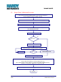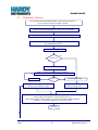
1
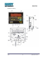
User’s Guide Enviro™ Series Checkweighing Instrument © 2009 by Hardy Instruments, Inc. 12/09 All rights reserved Document Part Number 0596-0315-01 Revision B Enviro™ Series Instrument Document Part Number 0596-0315-01 Revision B Hardy Instruments Inc. 9440 Carroll Park Drive, Suite 150 San Diego, CA 92121 Created 12/09 Created Document Revision B 12/09 Released Manual Disclaimer Every effort has been made to provide complete and accurate information in this manual. However, although this manual may include a specifically identified warranty notice for the product, Hardy Instruments makes no representations or warranties with respect to the contents of this manual, and reserves the right to make changes to this manual without notice when and as improvements are made. Hardy Instruments shall not be liable for any loss, damage, cost of repairs, incidental or consequential damages of any kind, whether or not based on express or implied warranty, contract, negligence, or strict liability arising in connection with the design, development, installation, or use the scale. © Copyright 2009 This document contains proprietary information protected by copyright. All rights are reserved; no part of this manual may be reproduced, copied, translated or transmitted in any form or by any means without prior written permission of the manufacturer. 12/09 i 0596-0315-01 Rev B Section 1: General Information Table of Contents SECTION 1 1.1. 1.2. SECTION 2 2.1. SECTION 3 3.1. 3.2. SECTION 4 4.1. 4.2. 4.3. 4.4. 4.5. SECTION 5 5.1 5.2 5.3 5.4 SECTION 6 6.1 6.2 6.3 SECTION 7 7.1. 7.2. 7.3. SECTION 8 12/09 GENERAL INFORMATION ..............................................................................................1 Introduction .........................................................................................................................1 Specifications .....................................................................................................................1 SERVICE POLICY INFORMATION..................................................................................2 General Service Policy .......................................................................................................2 INSTALLATION ................................................................................................................3 Prior to installation ..............................................................................................................3 3.1.2 Unpacking .........................................................................................................3 Finding the Best Location .................................................................................3 3.1.3 Mounting and Wiring the Indicator .....................................................................................4 3.2.1 Basic Installation Steps .....................................................................................4 Connecting to the Load Cells ............................................................................5 3.2.2 Remote switches ...............................................................................................5 3.2.3 Powering Up the Indicator.................................................................................6 3.2.4 PROGRAMMING CONFIGURATION...............................................................................7 Overall Steps ......................................................................................................................7 Introduction .........................................................................................................................7 Keypad functions, Programming Mode. .............................................................................8 MENU ACCESS .................................................................................................................8 Programming Steps ............................................................................................................9 Setup Menu .......................................................................................................................9 Config Menu ....................................................................................................................11 APP Menu .......................................................................................................................13 CALIBRATING THE INDICATOR ..................................................................................15 Introduction ......................................................................................................................15 Single Point Calibration Procedure .................................................................................16 Multipoint Calibration .......................................................................................................18 Service Sealing ...............................................................................................................20 Commercial Applications.................................................................................................20 SERIAL I/O .....................................................................................................................21 Introduction .......................................................................................................................21 Connections ...................................................................................................................21 Printers ............................................................................................................................21 Remote display................................................................................................................22 Computer output..............................................................................................................22 OPERATIONS.................................................................................................................23 Basic Scale Operations ....................................................................................................23 KEYPAD FUNCTIONS, Weigh mode ..............................................................................23 Instrument Weighing Functions ........................................................................................23 Gross/Tare/Net Weighing................................................................................................24 SERVICE & MAINTENANCE .........................................................................................30 ii 0596-0315-01 Rev B 8.1. 8.2 SECTION 9 Expanded Display Mode ..................................................................................................30 Scale Maintenance ...........................................................................................................30 8.2.1 Cleaning the Scale and Indicator ....................................................................30 PARTS LIST ...................................................................................................................31 APPENDIX I KEYPAD REFERENCE ..................................................................................................33 12/09 iii 0596-0315-01 Rev B Section 1 General Information 1.1. INTRODUCTION The Enviro™ Series instrument is designed for light capacity, general purpose use. It is also designed for use in wash-down Environments. Features The Indicator has a capacity setting of up to six digits, using a six-digit amber LED display. Annunciators include, Net Weight, Units, Under, Accept, Over, and Accumulation. Checkweigh mode can store up to four Checkweigh recipes. 1.2. SPECIFICATIONS FEATURE DESCRIPTION Display 1.25” Segmented LED. ─ 12 amber segments for under-weighments. ─ 12 green segments for correct weighments. ─ 12 red segments for over-weighments. Display Update Rate 0.1 – 1.0 second, selectable Capacity Up to 999990 programmable Resolution 10,000 divisions, commercial. 100,000 divisions, non-commercial. 8,000,000 divisions, internal. Division Sizes 0.0001 – 50, selectable. Load Cell(s) Up to four (4) 350 ohm cells. Electrical 120 VAC or 240 VAC, selectable. Dimensions 9.8” x 7.6” x 3.3” Environment IP69K heavy washdown Operating Temperature Range -10º C to +40º C 14º F – 104º F Communications RS232 or RS485 bidirectional serial communications port Units lbs, oz, kg, g and lbs/oz, or custom Instrument Approvals CC: 09-024 MC: Pending ETL: ETL Listing Pending ─ 12/09 1 0596-0315-01 Rev B Section 2: Service Policy Section 2 Service Policy Information 2.1. GENERAL SERVICE POLICY Customers are responsible to protect the equipment from accidental or malicious damage. Do not install or operate the equipment where the application requirements exceed the design specifications of the equipment. Do not make physical, electrical or program modifications to this equipment. Failure to comply with this policy voids all implied and/or written warranties. The installing technician should verify the equipment's capabilities and limitations as part of the installation process. All electrical assemblies must be returned intact for replacement credit using the standard procedures. At the time of installation, all electronic and mechanical adjustments are considered to be part of the installation, and are included in the installation charge(s). The AC receptacle/outlet shall be located near the Indicator and easily accessible. Make no electrical connections that are not specified in the installation guidelines. The equipment consists of printed circuit assemblies which must be handled using ESD handling procedures, and must be replaced as units. ─ Replacement of individual components is not allowed. ─ The assemblies must be properly packaged in ESD protective material and returned intact for replacement credit per normal procedures. Hardy Instruments appreciates your business. Should you not understand any information in this manual or experience any problem with the product, contact our Customer Service Department at: Phone: (858) 278-2900 FAX: (858) 278-6700 Web Site: www.hardyinst.com Support e-mail address: [email protected] 12/09 2 0596-0315-01 Rev B Section 3: Installation Section 3 Installation 3.1. PRIOR TO INSTALLATION 1. Unpack and Check contents 2. Find best location 3.1.2 Unpacking Follow these guidelines when unpacking all equipment: Check in all components and accessories according to your order. Keep the shipping container and packing material for future use. Remove all components from their packing material, checking against the invoice that they are accounted for and not damaged. If damage has occurred: ─ Advise the shipper immediately, if damage has occurred. ─ Order any parts necessary to replace those which have been damaged. Check the packing list. Collect all necessary installation manuals for the equipment and accessories. Open the equipment and perform an inspection, making certain that all hardware, electrical connections and printed circuit assemblies are secure. Do not reinstall the cover if the final installation is to be performed after the pre-installation Checkout. 3.1.3 Finding the Best Location Position the equipment with these points in mind: Intense direct sunlight can harm the display. Do not locate near magnetic material or equipment/Indicators which use magnets in their design. Avoid areas which have extreme variations in room temperatures. Temperatures outside the Indicator’s specifications will affect the weighing accuracy of this product. Do not open the Indicator if there is evidence of damage to it or any other scale component or supporting structure. When selecting the right location for the Indicator and the scale, keep the components completely away from all high water, such as low-lying areas that may flood, and away from any drain pipes. 12/09 3 0596-0315-01 Rev B Section 3: Installation IMPORTANT INSTALLATION NOTICE All load cells, load cell cables, and interconnecting cables used to connect all scale components shall be located a minimum of thirty-six (36”) inches distance away from all single and multiple phase high energy circuits and electric current carrying conductors. This includes digital weight indicators, junction boxes, sectional controllers, and power supplies. This includes any peripheral devices, such as printers, remote displays, relay boxes, remote terminals, card readers, and auxiliary data entry devices. Also included is the scale components themselves, such as 120 volt AC, 240 volt AC, 480 volt AC and electric supply of higher voltage wiring runs and stations, AC power transformers, overhead or buried cables, electric distribution panels, electric motors, florescent and high intensity lighting which utilize ballast assemblies, electric heating equipment, traffic light wiring and power, and relay boxes. All scale components, including digital weight indicators and peripheral devices are not designed to operate on internal combustion engine driven electric generators and other similar equipment. Electric arc welding can severely damage scale components such as digital weight indicators, junction boxes, sectional controllers, power supplies, and load cells. For additional information, please contact the Hardy Instruments Technical Services Department. 3.2. MOUNTING AND WIRING THE INDICATOR 3.2.1 Basic Installation Steps The Enviro™ Series Indicators arrive fully assembled. The factory default setting for the Enviro™ Series is 110 to 120 VAC. For 220 to 240 VAC operations, change the setting as shown below before powering up the unit. Ensure the AC power cord is disconnected from any power sources. Remove the cover and place the unit face down on a bench. On the main PC board, locate the jumpers at J4 1. 12/09 Remove the jumpers from the 117V positions and replace one of them on the 220V position as shown. 4 0596-0315-01 Rev B Section 3: Installation 2. Remove the 120 VAC plug from the end of the power cord and attach a proper 220-240 VAC plug. Connect the green wire and the shield to the ground lug. Note: The original wiring connects brown to AC hot and blue to neutral. 3. Reattach all cables and replace the front cover assembly. Caution: Improper connections at J4 can cause catastrophic damage to the Indicator 3.2.2 Connecting to the Load Cells Connect the bench scale interface cable wires to the terminal strip TB1 on the small block pcb as follows: TB1 Pin no. FUNCTION 1 () Excitation 2 (+) Excitation 3 (+) Sense 4 (-) Sense 6 Shield 7 (+) Signal 8 () Signal Pin numbers added for clarity Notes: No internal sense jumpers are provided. Jumpers must be installed from +Excitation to +Sense and from –Excitation to –Sense if no sense leads are used. Refer to the appropriate Enviro™ Series Bench Scale Service Manual for the proper interface wiring color code. Reassemble housing and proceed with installation. 3.2.3 Remote switches The Enviro™ Series has three available remote switch inputs. A dry contact normally open switch can be mounted and operated remotely using the connections on TB3. 12/09 5 0596-0315-01 Rev B Section 3: Installation 3.2.4 Powering Up the Indicator The Indicator performs a warm-up cycle. The Indicator initiates a test, displaying numbers 1 to 8, and lights up all LED’s. The Program number and Revision Information displays. The Indicator then displays the current weight on the scale 12/09 6 0596-0315-01 Rev B Section 3: Installation Section 4 Programming Configuration 4.1. OVERALL STEPS Follow these steps to program the Enviro™ Series instrument. 1. Configure the Enviro™ Series Instrument operating parameters. 2. Calibrate the Enviro™ Series Instrument. 3. Set up the Enviro™ Series Instrument options. 4.2. INTRODUCTION The program group is shown and accessed in steps. Each program group may be entered and modified, or skipped to the next group. At each step, a word or abbreviation displays, indicating the parameter to be set. Each step then may be viewed or modified. At the end of programming a SAVE prompt will be displayed. Press Program/Enter to SAVE and exit or scroll to CANCEL to disregard changes made. The following is a rendering of the four programming groups. Pressing Over/Under/Next or tare will scroll through the choices listed. Program/enter will enter the program steps in a particular group. See chart in Sec 4.3 for full details of front panel pushbuttons for programming mode. SEtuP ConFiG APP CAL donE SAvE 12/09 7 CAncEL 0596-0315-01 Rev B Section 6: Serial I/O 4.3. KEYPAD FUNCTIONS, PROGRAMMING MODE. This chart shows what action will be taken when a front panel key is pressed in the programming mode. KEY ACTION 1 No function in programming mode. Exception, decrements selected digit when entering numeric data. 2 No function in programming mode. Exception exits to done prompt when entering numeric data. 3 No function in programming mode. Exception, moves flashing digit to far left position when entering numeric data. 4 No function in programming mode. TARE Scrolls backwards through the choices for each program step. Exception, moves flashing digit left when entering numeric data. ZERO Accepts the displayed value and advances to the next program step like enter. Exception, resets all digits to zeroes when entering numeric data. PROGRAM ENTER Accepts the displayed value and advances to the next program step. OVER/UNDER NEXT Scrolls forward through the choices for each program step. Exception, moves flashing digit right when entering numeric data. UNITS Scrolls forward through the choices for each program step Exception, increments digit when entering numeric data. B/G NET Scrolls backward through programming steps. Returns to the Weigh Mode after multiple pressings. PRINT No function in programming mode. Scrolls decimal point to the right in CAL mode. 4.4. MENU ACCESS This chart shows which menus can be accessed from the front panel based on the security level setting and the internal jumper (JP1) position. SL0 SL0 SL1 SL1 SL2 SL2 SL3 SL3 SL4 SL4 SL5 SL5 JP1 JP1 JP1 JP1 JP1 JP1 JP1 JP1 JP1 JP1 JP1 JP1 MENU Out In Out In Out In Out In Out In Out In SEtUP Y Y Y Y Y Y Y Y N N N N ConFiG Y N Y N Y N N N N N N N APP Y Y Y Y Y Y Y Y N N N N CAL Y N Y N N N N N N N N N 12/09 8 0596-0315-01 Rev B Section 6: Serial I/O 4.5. PROGRAMMING STEPS Setup Menu 1. Press and hold the Program/Enter key or press S1 on the main PCB to display SEtuP. 2. Press the Program/Enter key to enter setup mode. 3. Press Zero to set the desired Programming Menu. Default selections are shown underlined. Programming time format: This will determine whether the clock is displayed and printed in 24 hour (military) or 12 hour (AM/PM) format. The display will indicate either 12 hour or 24 hour. Press Over/Under/Next or tare to change the selection. Press Program/Enter to enter the selection. Set-ti: Programming the Time: Time is set as HH.MM.SS and must be entered in military format. The display will indicate set-ti followed by the current time with the 10s digit of the hour flashing. Press units to increase the digit or the 1 button to decrease the digit. Press Over/Under/Next to move the flashing digit right or press tare to move the flashing digit left. When the time is correct, press Program/Enter to accept the time and go to the next step. Set-da: Programming the date: Date is set as MM.DD.YY format. The display will indicate set-da followed by the current date with the 10s digit of the month flashing. Press units to increase the digit or the 1 button to decrease the digit. Press Over/Under/Next to move the flashing digit right or press tare to move the flashing digit left. When the date is correct, press Program/Enter to accept the date and go to the next step. Id: Scale ID: This step sets the scale ID from 1-32. The display will indicate id xx where xx is the current ID setting. Press Over/Under/Next or units to increase the setting, or press tare to decrease the setting. When the correct ID is displayed, press Program/Enter to enter the value. The default Id is 01. Port 1: Programming Port 1: The display will indicate port 1, then output, then the current setting. Press over/under/next, units or tare to scroll through the available choices. Press Program/Enter to enter the correct selection. Available selections are: OFF PoLL PoLLid Contin button Auto diS Function is not active. Computer demand mode. Computer demand mode with ID. Continuous output. Transmit when print is pressed. Transmit occurs when Autoprint threshold is met or exceeded. Continuous output using remote display format. Baud: Programming Port 1 baud rate: The display will indicate baud then the current setting. Press Over/Under/Next or units to scroll up, or tare to scroll down through the available choices. Press Program/Enter to enter the selection. Available selections are: 300 9600 600 19200 1200 38400 2400 57600 4800 115200 Dbit: Programming Port 1 data bits: The display will indicate dbit x where x is either 7 or 8. Press Over/Under/Next , units , or tare to select proper value. Press Program/Enter to enter proper selection. 12/09 9 0596-0315-01 Rev B Section 6: Serial I/O P: Programming Port 1 Parity setting: The display will indicate p along with the current setting. Press over/under/next, units or tare to change the selection. Press Program/Enter to enter the selection. Available selections are: P nonE P odd P EvEn Busy: Programming Port 1 handshaking: The display will indicate xxbusy, where xx is either no, lo, or hi. Press over/under/next, units or tare to change the selection. Press Program/Enter to enter the selection. Opti: Include time data with transmitted data: This determines whether or not to include the time in the data string for Port 1. Display will indicate opti followed by the current selection of Y for yes to include, or n for no to exclude. Press over/under/next, units or tare to change the selection. Press Program/Enter to enter the selection. Opda: Include date data with transmitted data: This determines whether or not to include the date in the data string for Port 1. Display will indicate opda followed by the current selection of Y for yes to include, or n for no to exclude. Press over/under/next, units or tare to change the selection. Press Program/Enter to enter the selection. Opid: Include ID data with transmitted data: This determines whether or not to include the ID in the data string for Port 1. Display will indicate opid followed by the current selection of Y for yes to include, or n for no to exclude. Press over/under/next, units or tare to change the selection. Press Program/Enter to enter the selection. Port 2: Programming Port 2: The display will indicate port 2, then output, then the current setting. Press over/under/next, units or tare to scroll through the available choices. Press Program/Enter to enter the correct selection. Available selections are: OFF PoLL PoLLid Function is not active. Computer demand mode. Computer demand mode with ID. Note: If b/g / net is pressed after Port 2, the indicator will revert back to ID. Baud: Programming Port 2 baud rate: The display will indicate baud then the current setting. Press Over/Under/Next or units to scroll up, or tare to scroll down through the available choices. Press Program/Enter to enter the selection. Available selections are: 300 9600 600 19200 1200 38400 2400 57600 4800 115200 Dbit: Programming Port 2 data bits: The display will indicate dbit x where x is either 7 or 8. Press over/under/next, units, or tare to select proper value. Press Program/Enter to enter proper selection. P: Programming Port 2 Parity setting: The display will indicate p along with the current setting. Press over/under/next, units or tare to change the selection. Press Program/Enter to enter the selection. Available selections are: P nonE P odd P EvEn Opti: Include time data with transmitted data: This determines whether or not to include the time in the data string for Port 2. Display will indicate opti followed by the current selection of Y for yes to include, or n for no to exclude. Press over/under/next, units or tare to change the selection. Press Program/Enter to enter the selection. Opda: Include date data with transmitted data: This determines whether or not to include the date in the data string for Port 2. Display will indicate opda followed by the current selection of Y for yes to include, or n for no to exclude. Press over/under/next, units or tare to change the selection. Press Program/Enter to enter the selection. 12/09 10 0596-0315-01 Rev B Section 6: Serial I/O Opid: Include ID data with transmitted data: This determines whether or not to include the ID in the data string for Port 2. Display will indicate opid followed by the current selection of Y for yes to include, or n for no to exclude. Press over/under/next, units or tare to change the selection. Press Program/Enter to enter the selection. Int: Display brightness setting: This changes the intensity of the display brightness. The display will indicate int followed by the intensity setting from 1-7, with 7 being the brightest. Press Over/Under/Next or units to scroll up, or tare to scroll down through the available choices. Press Program/Enter to enter the selection. The default setting is 4. The Enviro™ Series indicator will now return to the setup prompt. Navigate to the desired menu heading to continue programming, or to done to finish. Config Menu 1. Press and hold the Program/Enter key or press S1 on the main PCB to display SEtUP. 2. Press Units or Over/Under/Next to display ConFiG. 3. Press the Program/Enter key to enter setup menu. Cap: Programming the scale capacity: The display will indicate cap followed by the current setting with the most significant digit blinking. Press units to scroll up, or the 1 to scroll down to the desired numeric value. The Over/Under/Next key will move the flashing digit to the right, and the tare key will move it left. Press Program/Enter when the display shows the correct capacity setting. Note: Capacity can be up to six displayed digits (999999). Units: Programming the scale units: The display will indicate units, and the current setting by displaying a lit LED symbol next to the printed unit legend beside the display. Press over/under/next, units or tare to scroll through all the possible choices. Press Program/Enter to enter the selection. Available selections are: lb/oz/kg/g lb/kg/g oz/kg/g kg/g lb/oz/kg lb/kg oz/kg kg lb/oz/g lb/g oz/g g lb/oz lb oz Notes: 1. The lb-oz and custom unit settings cannot be used as the Primary Unit in the Enviro™ Series. 2. The lb-oz and custom unit settings are not legal for trade. P-unit: Programming the primary unit: (the unit that the instrument will default to upon power up) The display will indicate p-unit and indicate the current setting by displaying the lit LED next to the printed unit legend beside the display. Press over/under/next, units or tare while observing the LED which will change to indicate the selection. Press Program/Enter to enter the selection. Available selections are: lb g kg oz Note: Selection availability dependant upon programmed units selection. lboz: pounds-ounces mode: The display will indicate lboz and the current selection, either y for enable or n for disable. Press over/under/next, units or tare to change the selection. Press Program/Enter to enter the selection. 12/09 11 0596-0315-01 Rev B Section 6: Serial I/O Cust: Custom units. The display will indicate cust and the current selection, either y for enable or n for disable. Press over/under/next, units or tare to change the selection. Press Program/Enter to enter the selection. Note: When custom units are active, units LED indicators are off in the weigh mode. Azt: Programming the Automatic Zero Tracking band: (this feature will maintain zero when small amounts of material are placed on the scale, such as rain, snow, debris, etc.) The display will indicate azt x where x is the current setting. Press over/under/next, units or tare to change the selection. Press Program/Enter to enter the selection. Available selections are: OFF 0.5 1 3 Function is not active. half of a division / increment / graduation one division / increment / graduation three divisions / increments / graduations Bal: Programming the motion band (the range in divisions/increments/graduations that weight must be stable before a print, zero, or tare function will be allowed). The display will indicate bal x where x is the current setting. Press over/under/next, units or tare to change the selection. Press Program/Enter to enter the selection. Available selections are: OFF 0.5 1 3 Function is not active. half of a division / increment / graduation one division / increment / graduation three divisions / increments / graduations O.r: Programming the zero range: (the percentage of scale capacity that may be removed by pressing the Zero Key). The display will indicate o.r x where x is the current setting. Press over/under/next, units or tare to change the selection. Press Program/Enter to enter the selection. Available selections are: 100 percent zero range 2 percent zero range 100 2 D: Programming the division size: The display will indicate d followed by the current division size setting. Press Over/Under/Next or units to scroll up, or tare to scroll down through the available choices. Press Program/Enter to enter the selection. Available selections are: 50 0.5 0.005 20 0.2 0.002 10 0.1 0.001 5 0.05 0.0005 2 0.02 0.0002 1 0.01 0.0001 Filter: Programming the filter setting: (intended to minimize the effects of motion, vibration, and wind currents) The display will indicate filter followed by the current filter setting. Press Over/Under/Next or units to scroll up, or tare to scroll down through the available choices. Press Program/Enter to enter the selection. Available selections are: 1 3 5 11 15 20 30 50 Flf: Flush filter factor: Allows indicator to switch to fast filter rate if weight change exceeds the number of divisions in setting. The display will indicate flf followed by the current setting. Press Over/Under/Next or units to scroll up, or tare to scroll down through the available choices. Press Program/Enter to enter the selection. Available selections are: oFF 1 2 5 10 20 50 100 Tare: Programming the tare setting: (the means by which a container’s weight may be removed, to set the indicator to display the net weight only) The display will indicate tare followed by the current tare setting. 12/09 12 0596-0315-01 Rev B Section 6: Serial I/O Press over/under/next, units or tare to change the selection. Press Program/Enter to enter the selection. Available selections are: OFF Tare is disabled. ON Tare is active. On-CLr Tare automatically clears when Gross weight returns to Zero Hl: Overload limit: The actual value at which the display goes to ol (represented as a percentage of capacity). The display will indicate hl followed by the current setting. Press Over/Under/Next or units to scroll up, or tare to scroll down through the available choices. Press Program/Enter to enter the selection. Available selections are: 103 102.5 105 110 300 Ul: Underload limit: The actual value at which the display goes to ul (represented as a percentage of capacity behind zero). The display will indicate ul followed by the current setting. Press Over/Under/Next or units to scroll up, or tare to scroll down through the available choices. Press Program/Enter to enter the selection. Available selections are: 5.5 10 25 50 100 D rate: Programming the display update rate: The times between display updates in seconds. The display will indicate d rate and then the current setting. Press Over/Under/Next or units to scroll up, or tare to scroll down through the available choices. Press Program/Enter to enter the selection. Available selections are: 0.1 0.2 0.3 0.4 0.5 0.6 0.7 0.8 0.9 1.0 P1: Output format of Port1, GTN or net only: This determines whether the output from Port1 will be transmitted as a net weight only or a gross/tare/net weighment. The display will indicate p1 followed by the current setting. Press over/under/next, units or tare to change the selection. Press Program/Enter to enter the selection. Available choices are: Gtn nEt P2: Output format of Port2, GTN or net only: This determines whether the output from Port2 will be transmitted as a net weight only or a gross/tare/net weighment. The display will indicate p1 followed by the current setting. Press over/under/next, units or tare to change the selection. Press Program/Enter to enter the selection. Available choices are: Gtn nEt The Enviro™ Series indicator will now return to the config prompt. Navigate to the desired menu heading to continue programming, or to done to finish. APP Menu 1. Press and hold the Program/Enter key or press S1 on the main PCB to display SEtUP. 2. Press Units or Over/Under/Next twice to display APP. 3. Press the Program/Enter key to enter APP menu. 12/09 13 0596-0315-01 Rev B Section 6: Serial I/O X.xxupd: Display microvolts per division: This is a reference to display the current microvolts per division. The display will indicate x.xxupd where x.xx is a numeric value of the microvolts per division. Press any front panel pushbutton other than b/g / net to continue. Acc: Accumulate feature enabled: Enables or disables the accumulate feature. The display will indicate acc followed by the current setting of y for enable and n for disable. Press over/under/next, units or tare to change the selection. Press Program/Enter to enter the selection. A thld: Autoprint and accumulate threshold: This is the number of divisions the indicator must meet or exceed for an autoprint or an auto-accumulation to occur. The display will indicate a thld, followed by the current setting in divisions with the left digit flashing. Press units to increase the digit, press the 1 key to decrease the flashing digit. Press Over/Under/Next to move the flashing digit to the right or press the tare to move it to the left. Press Program/Enter when the display shows the correct threshold setting. The acceptable range is 1 to 1000 and default value is 10 divisions. Aout: Autoprint and autoaccumulate output: This setting will determine whether the indicator will autoprint during an automatic accumulation. This setting is only active if port 1 is set to auto and accumulation is enabled. The display will indicate aout followed by a y for enable or an n for disable. Press over/under/next, units or tare to change the selection. Press Program/Enter to enter the selection. Beep: Audible tone when key is pressed: This will enable or disable the audible tone to acknowledge pressing a front panel key. The display will indicate beep followed by a Y for enable or an n for disable. Press over/under/next, units or tare to change the selection. Press Program/Enter to enter the selection. C-fact: Conversion factor for custom units: The primary units divided by this value will determine the custom units if it is enabled. The display will indicate c-fact followed by a value with the left digit flashing. Press units to increase the digit, press the 1 key to decrease the flashing digit. Press Over/Under/Next to move the flashing digit to the right or press the tare to move it to the left. Press print to move the decimal point to the right. Press Program/Enter when the display shows the correct conversion factor. Note: An example of custom units might be to display the weight in tons. In this case the conversion factor is 2000.0 if the primary unit is lb. The default conversion factor is 8.3333. The Enviro™ Series indicator will now return to the setup prompt. Navigate to the desired menu heading to continue programming, or to done to finish. 12/09 14 0596-0315-01 Rev B Section 6: Serial I/O Section 5 Calibrating the Indicator 5.1 Introduction Calibration can be performed entirely from the front panel or locked out with security levels 2-5 or internal jumper JP1. Calibration can be performed with a single calibration point, or using up to four calibration points. SL0 SL0 SL1 SL1 SL2 SL2 SL3 SL3 SL4 SL4 SL5 SL5 JP1 JP1 JP1 JP1 JP1 JP1 JP1 JP1 JP1 JP1 JP1 JP1 MENU Out In Out In Out In Out In Out In Out In SEtUP Y Y Y Y Y Y Y Y N N N N COnFIG Y N Y N Y N N N N N N N APP Y Y Y Y Y Y Y Y N N N N CAL Y N Y N N N N N N N N N Menu access based on security level (SL) and internal calibration jumper (JP1) The following flow charts show step by step instructions for a single point calibration, and a multipoint calibration. 12/09 15 0596-0315-01 Rev B Section 6: Serial I/O 5.2 Single Point Calibration Procedure Press and hold the PROGRAM/ENTER key until “SEtUP is displayed. Or press internal switch S1 to display “SEtUP” Press the OVER/UNDER/NEXT key until “CAL” is displayed Press the PROGRAM/ENTER key to display security level “SL” Press OVER/UNDER/NEXT to select proper security level Press PROGRAM/ENTER Raw counts displayed No New Zero? Yes Press the ZERO key Scale zero’d. Raw counts become zero reference ZERO Press PROGRAM/ENTER Displays a calibration weight Enter test weight value. Most Significant digit blinks. Increase digit with UNITS key. Decrease digit with 1 key. Move flashing digit left using TARE key, or right using OVER/UNDER/NEXT key. ZERO key clears display, PRINT moves decimal to right. When display shows correct test weight press PROGRAM/ENTER Next page 12/09 16 0596-0315-01 Rev B Section 6: Serial I/O Displays “LOAd1”, then raw counts Apply test weights to scale. Press PROGRAM/ENTER key Displays correct weight. Note: UNITS LED blinking Press the 2 key or internal S1 Displays microvolts per division (x.xxuPd)* Press any front panel key to return to “CAL” prompt Press OVER/UNDER/NEXT to display “donE” Press PROGRAM/ENTER to display “SAvE” Press PROGRAM/ENTER to display “SAvEd” Scale returns to weigh mode *The “uPd” (microvolts per division) must be one (1.0) or greater for proper operation. 12/09 17 0596-0315-01 Rev B Section 6: Serial I/O 5.3 Multipoint Calibration Press and hold the PROGRAM/ENTER key until “SEtUP is displayed. Or press internal switch S1 to display “SEtUP” Press the OVER/UNDER/NEXT key until “CAL” is displayed Press the PROGRAM/ENTER key to display security level “SL” Press OVER/UNDER/NEXT to select proper security level Press PROGRAM/ENTER Raw counts displayed No New Zero? Yes Press the ZERO key Scale zero’d. Raw counts become zero reference ZERO Press Displays “CALAt2”, “CALAt3”, or “CALAt4”, then calibration weight PROGRAM/ENTER Displays “CALAt1”, then a calibration weight value Enter test weight value. Most Significant digit blinks. Increase digit with UNITS key. Decrease digit with 1 key. Move flashing digit left using TARE key, or right using OVER/UNDER/NEXT key. ZERO key clears display, PRINT moves decimal to right. Next page 12/09 18 0596-0315-01 Rev B Section 6: Serial I/O When display shows correct test weight press PROGRAM/ENTER Displays “LOAd1”, “LOAd2”, “LOAd3”, or “LOAd4” then raw counts Apply test weights to scale. Press PROGRAM/ENTER key Fourth span point entered Displays correct weight. Note: UNITS LED blinking PROGRAM/ENTER Press 2 key or internal switch S1 Displays microvolts per division (x.xxuPd)* Press any front panel key to return to “CAL” prompt Press OVER/UNDER/NEXT to display “donE” Press PROGRAM/ENTER to display “SAvE” Press PROGRAM/ENTER to display “SAvEd” Scale returns to weigh mode *The “uPd” (microvolts per division) must be one (1.0) or greater for proper operation. 12/09 19 0596-0315-01 Rev B Section 6: Serial I/O 5.4 Service Sealing Commercial Applications Scales used in a commercial application must be “placed in service” in accordance to local weights and measures guidelines. Four sealing screws are provided on the back cover to allow a lead seal to be installed if required. An audit trail is provided to track changes in programming and calibration. Access to the audit trail is as follows: 1. Press and hold b/g / net for approximately 10 seconds. 2. Indicator will display cfgctr. This is for the configuration audit. 3. Press Over/Under/Next to toggle to calctr. This is for the calibration audit. Repeated pressing of this button will toggle between the two choices. 4. At either prompt, cfgctr or calctr, press program/enter. This will display the audit counter for that particular audit trail. 5. If connected to a printer, print may be pressed at this time to print both audit trail counters. 6. Press Program/Enter again to return to cfgctr or calctr. Both audit trails can be viewed without returning to the weigh mode. 7. When finished viewing audit trails, press units to return to normal weighing. 12/09 20 0596-0315-01 Rev B Section 6: Serial I/O Section 6 Serial I/O 6.1 INTRODUCTION The Enviro™ Series Indicator is equipped with 2 serial output ports. Port 1 is a bidirectional rs232 port, and Port 2 is a bidirectional rs485 port. Port 1 can be configured to operate with a variety of printers, computer applications, and remote displays. 6.2 CONNECTIONS Port 1 designation Tb1 pin Tb2 pin Port 2 designation 1 Chassis ground 1 RS485+ 2 Receive data (RX) 2 RS485- 3 Transmit data (TX) 3 Signal ground 4 Clear to send (CTS) 5 Signal ground (GND) 6 Request to send (RTS) 6.3 PRINTERS Printers Please see the Enviro™ Series Printer Addendum for a list of suggested 3rd party printers and how to configure the Enviro™ Series check weighing instrument to work with them. 12/09 21 0596-0315-01 Rev B Section 6: Serial I/O Remote display Please see the Enviro™ Series Printer Addendum for a list of suggested 3rd party remote displays and how to configure the Enviro™ Series check weighing instrument to work with them. Computer output The Enviro™ Series can be connected to a variety of computer systems utilizing the continuous or polled outputs. Connections to computers are done using the wiring chart provided earlier in this section. Ensure that all protocol (baud rate, parity, etc) matches at both devices connected. Up to 6 data items are available for transmission; Gross, Tare, Net, Time, Date, and ID in that order. Each item is separated by a carriage return (CR) and a line feed (LF). All items enabled in the setup menu will be sent. If the indicator is in Gross mode, only gross weight will be sent. If the indicator is in Net mode, gross, tare and net will be sent if GTN is selected in config menu, or net only if NET is selected. The table below shows a typical wiring diagram to a computer equipped with a db9 connector. Enviro™ Series tb1 Computer 2 RX 3 TX 3 TX 2 RX 5 Gnd 5 Gnd 12/09 22 0596-0315-01 Rev B Section 7: Operations Section 7 Operations 7.1. BASIC SCALE OPERATIONS Upon power up the Indicator performs a warm-up cycle. The Indicator initiates a test, displaying numbers 1 to 8, and lights up all LED’s. The Program number and Revision Information displays. The Indicator then displays the current weight on the scale 7.2. KEYPAD FUNCTIONS, WEIGH MODE KEY ACTION Recipe 1-4 Enables or disables programmed recipe in Checkweigh mode. In peak weigh mode, 1 enables peak, 2 disables, and 3 resets peak. TARE Automatically tares off the displayed weight. If held for 3 seconds, enables or disables accumulate function. ZERO Resets gross weight to center of zero. PROGRAM/ENTER Captures weight and adds to accumulation if enabled. OVER/UNDER/NEXT Displays accumulated weight and number of weighments if enabled. If held for 3 seconds, enters Checkweigh or peak weight setup. UNITS Switches between selected weighting units. B/G – NET Toggles between gross and net weights. If held for 10 seconds, displays audit trail functions. PRINT Transmits transaction data out com port 1 if button is selected. 7.3. INSTRUMENT WEIGHING FUNCTIONS Basic Weighing Ensure that the bench scale is empty, power on the indicator, press the zero key and the display indicates “0” and is ready for use. Gross Weighing 1. Press the b/g / net key, if required, to set the display to GR (gross). 2. Press the zero key, if required, to set scale to “0.” 3. Place container/object on the scale platform. 4. Read the gross weight on the display. Net Weighing 12/09 1. Press the b/g / net key, if required, to set display to GR (gross). 2. Press the zero key, if required, to set scale to “0.” 23 0596-0315-01 Rev B Section 7: Operations 3. Place container/object on scale (Tare weight). 4. Press the tare key. 5. Place material in container or add objects (Net weight). 6. Read the net weight on the display. Gross/Tare/Net Weighing 1. Press the B/G / Net key, if required, to set display to GR (gross). 2. Press the Zero key, if required, to set scale to “0.” 3. Place container/object on scale (Tare weight). 4. Press the Tare key. 5. Place material in container or add objects (Net weight). 6. Read the net weight on the display. 7. Press the B/G / Net key to switch to Gross and view Gross weight. Weight Accumulation Starting accumulation mode 1. If indicator is not in accumulate mode, press and hold tare to enable accumulate mode. Indicator will display acc on briefly. Note: If Accumulate function is not enabled in setup menu, display will flash and return to displaying current weight without showing acc-on. 2. Press zero, if required, to set scale to “0.” 3. If accumulation is using a container, apply container and press tare to place scale in net mode. 4. Put the product to be accumulated on the bench scale. There are four possibilities of configuring the accumulation function. Each one will be addressed separately as follows: Port 1 set to auto and aout set to yes. 1. After weight is applied, and if the weight is greater than the accumulate threshold, the indicator will flash all the green ACCEPT LEDs for one second showing that the weight has been stored as an accumulation and then transmit the following data string: “Weight nn = wwwwww uu GR/NT” nn is the number of the current accumulated weight in numerical order. wwwwww is the last accumulated weight. uu is the unit of weight accumulated. GR or NT represent whether accumulated weight is gross or net respectively. 2. Weight on the scale must now be removed to less than .5 grads before the next accumulation can occur. 3. If a reprint of the last accumulated weight is required, press print and port 1 will retransmit the string indicated above. 4. Repeat steps 1-3 to continue accumulations (up to 99). 12/09 24 0596-0315-01 Rev B Section 7: Operations Port 1 set to Auto and Aout set to no. 1. After weight is applied, and if the weight is greater than the accumulate threshold, the indicator will flash all the green ACCEPT LEDs for one second showing that the weight has been stored as an accumulation. 2. If a print is to occur, press print and port 1 will transmit the following: “Weight nn = wwwwww uu GR/NT” nn is the number of the current accumulated weight in numerical order. wwwwww is the last accumulated weight. uu is the unit of weight accumulated. GR or NT represent whether accumulated weight is gross or net respectively. 3. Weight on the scale must now be removed to less than .5 grads before the next accumulation can occur. 4. Repeat steps 1-3 to continue accumulations (up to 99). Port 1 set to button and Aout set to yes. 1. After weight is applied, and if the weight is greater than the accumulate threshold press program/enter. The indicator will check to ensure there is no motion. If scale is in motion, the indicator will wait up to 10 seconds for motion to stop. If the weight is not stable after 10 seconds, the scale will disregard the request for accumulation. If stability occurs, the green ACCEPT LEDs will flash for 1 second showing that the weight has been stored as an accumulation. 2. If a print is to occur, press print and port 1 will transmit the following: “Weight nn = wwwwww uu GR/NT” nn is the number of the current accumulated weight in numerical order. wwwwww is the last accumulated weight. uu is the unit of weight accumulated. GR or NT represent whether accumulated weight is gross or net respectively. 3. Weight on the scale must now be removed to less than .5 grads before the next accumulation can occur. 4. Repeat steps 1-3 to continue accumulations (up to 99). Port 1 set to button and Aout set to no. After weight is applied, and if the weight is greater than the accumulate threshold press program/enter. The indicator will check to ensure there is no motion. If scale is in motion, the indicator will wait up to 10 seconds for motion to stop. If the weight is not stable after 10 seconds, the scale will disregard the request for accumulation. If stability occurs, the green ACCEPT LEDs will flash for 1 second showing that the weight has been stored as an accumulation. 1. If a print is to occur, press print and port 1 will transmit the following: “Weight nn = wwwwww uu GR/NT” nn is the number of the current accumulated weight in numerical order. wwwwww is the last accumulated weight. uu is the unit of weight accumulated. GR or NT represent whether accumulated weight is gross or net respectively. 12/09 25 0596-0315-01 Rev B Section 7: Operations 2. Weight on the scale must now be removed to less than .5 grads before the next accumulation can occur. 3. Repeat steps 1-3 to continue accumulations (up to 99). Displaying Accumulated Weight and Count. 1. Press and release Over/Under/Next The indicator will alternately display the total accumulated weight and the number of accumulations for two seconds each. The count is left justified followed by Acc, and the total weight is right justified. 2. The indicator will continue to alternately display the weight and count for 30 seconds or until Over/Under/Next is pressed again Note: The indicator must be displaying gross zero to display totals. An error of “not 00” will display if weight is not removed. Clearing accumulated weight and total. 1. With total/count displayed (see Displaying accumulated weight and count above), Press zero. 2. The indicator will display Clr N prompting the operator to not cleat total count and accumulation. If the totals are to be cleared, toggle to display Clr Y by pressing Over/Under/Next. With the correct choice displayed, press Program/Enter. 3. The indicator will briefly display Cleared when the accumulator is cleared. Printing accumulated weight and total. 4. With total/count displayed (see Displaying accumulated weight and count above), press Print. 5. Indicator will display All Y, prompting the operator to print all the individual weighments and the total accumulation. If only the totals are desired, toggle to display All N by pressing Over/Under/Next. With the correct choice displayed, press Program/Enter. 6. The indicator will print the accumulated weighments, if selected, followed by the total. 7. After the print has occurred, the indicator will display Clr N prompting the operator to not cleat total count and accumulation. If the totals are to be cleared, toggle to display Clr Y by pressing Over/Under/Next. With the correct choice displayed, press Program/Enter. 8. The indicator will briefly display Cleared when the accumulator is cleared. Deactivating accumulation To deactivate the accumulation mode, press and hold Tare for 3 seconds. The indicator will display Accoff briefly to indicate accumulation function has been deactivated. Accumulation Notes 1. No units switching is allowed if Accumulation is currently activated, or if an accumulation has been stored and not cleared. The message Nounts will be displayed if Units is pressed. 2. On power up or return from Program mode or Checkweigh Setup mode, if an accumulation has been stored in units other than Primary Units (PU in config menu), the accumulation units will be automatically selected. 3. If the accumulation units are no longer enabled on power up or return from Program mode or Checkweigh Setup mode, the accumulated values will be cleared and Primary Units will be selected. Peak Hold Weighing To enable peak hold: 1. Press and hold Over/Under/Next until display indicates Chec. 2. Press Over/Under/Next to display hold. 12/09 26 0596-0315-01 Rev B Section 7: Operations 3. Press Program/Enter to display Hold X, where X is either Y or N. 4. Press Over/Under/Next to display Hold Y if necessary. o 5. Note: Peak Hold function must not be used with Checkweighing. Press Program/Enter to display CSaved, and returns to weigh mode. Indicator is now in Peak Hold mode. To operate peak hold: 1. Press the 1 button to activate Peak Hold mode. The first three indicators for UNDER, ACCEPT and OVER will flash indicating Peak Hold is active. Also the indicators on the 1, 2, and 3 buttons will be on. 2. The display will now freeze on the largest weight applied to the bench scale. It will remain there even after weight is removed. 3. To deactivate the Peak Hold function while retaining the current peak weight, press the 2 button. Indicator will now return to normal weigh mode. Any weight applied now will not affect the stored peak weight. 4. To deactivate Peak Hold and clear the current peak weight, press the 3 button. Indicator now returns to normal weigh mode. 5. To reactivate Peak Hold after pressing either 2 or 3, press 1. Check Weighing The Enviro™ Series indicator uses a three color bar graph to indicate an item’s weight within three bands, Under, Accept, and Over. It is capable of storing four “recipes” or different Checkweigh configurations for four different products. Default selections are underlined. Configuring Checkweigh mode: 1. Press and hold Over/Under/Next until display indicates Chec. 2. Press Program/Enter to display rec 1. This indicates that the indicator is ready to accept configuration of recipe 1. 3. If another recipe is to be configured, press Over/Under/Next to scroll through to rec 2, rec 3, or rec 4. 4. With the desired recipe displayed, press Program/Enter to display EnA Y, or ENA N. o Note: If ENA N is selected in this step, the indicator will advance to the next enabled recipe, or return to the Chec prompt if none are enabled. 5. To toggle between choices press over/under/next. Selecting Y will enable the current recipe, and selecting N will disable it. 6. Press Program/Enter to advance to nEt n, or net y. 7. Press Over/Under/Next to toggle between nEt n, (Checkweigh in gross mode) or net y, (Checkweigh in net mode). 8. Press Program/Enter to display diS Y, or dis n. This will determine whether the numeric display is active or not while Checkweighing is active. 9. Press Over/Under/Next to toggle between diS Y, and dis n. o 12/09 Note: If weighing in net mode and numeric display is active, the indicator can accidentally be placed in the GROSS mode and the display then might not match the Checkweigh indication. 27 0596-0315-01 Rev B Section 7: Operations 10. With the desired selection displayed, press Program/Enter to display units. With units displayed, one of the units legends will be lit. This is the weigh units the Checkweigh limits will be defined by in the following steps. 11. Press Over/Under/Next to scroll through the choices, including custom units. 12. With the desired units legend lit, press Program/Enter to display hand y, or hAnd n. This determines the method for defining the acceptance band. Using hand y provides the user the ability to enter all ranges manually, whereby hAnd n provides the user the ability to use a sample weight for the accept target range. 13. Press Over/Under/Next to toggle between the two choices. 14. With the desired selection displayed, press program/enter. If hand y is selected, go to step 21. 15. If hand n is selected, the indicator will display live weight along with scrolling under, accept, and over indicators. The indicator is waiting for an acceptance range weight to be applied. Apply a sample weight of an acceptable value and press program/enter. This weight will be used to assist defining the start of accept and end of accept values. 16. The entire under bar graph and the first segment of the accept bar graph will be illuminated. The captured weight value is displayed with the leftmost digit flashing. This is the start of accept point. If the weight displayed needs to be altered, press units to increase the digit, or press 1 to decrease it. Press Over/Under/Next to move flashing digit to the right, or press tare to move it to the left. Press print to move the decimal point to the right. Press zero to display all zeroes on the display. When the correct start of accept value is displayed, press program/enter. 17. The first segment of the under will be illuminated along with a number with the leftmost digit flashing. This is the start of under point. Using the same procedure as identified in step 16 above, enter the correct value for the beginning of the under range, this could be 0. When the correct start of under value is displayed, press program/enter. 18. The entire under bar graph, the entire accept, and the first segment of the over bar graph will be illuminated. The captured weight value is displayed with the leftmost digit flashing. This is the end of accept point. If required using the same procedure as identified in step 16 above, enter the correct value for the end of the accept range. When the correct end of accept value is displayed, press program/enter. 19. The entire under bar graph, the entire accept, and the entire over bar graph will be illuminated. The last weight value is displayed with the leftmost digit flashing. This is the end of over point. Using the same procedure as identified in step 16 above, enter the correct value for the end of the accept range. When the correct end of over value is displayed, press program/enter. 20. The indicator will briefly display CSaved, then return to the weigh mode with the most recently configured recipe active. 21. If h and y is selected, the first segment of the under bar graph will be illuminated. A previously programmed weight value is displayed with the leftmost digit flashing. This is the start of under point. If the weight displayed needs to be altered, press units to increase the digit, or press 1 to decrease it. Press Over/Under/Next to move flashing digit to the right, or press tare to move it to the left. Press print to move the decimal point to the right. Press zero to display all zeroes on the display. When the correct start of under value is displayed, press program/enter. 22. The entire under bar graph and the first segment of the accept bar graph will be illuminated. A previously programmed weight value is displayed with the leftmost digit flashing. This is the start of accept point. If required using the same procedure as identified in step 21 above, enter the correct value for the start of the accept range. When the correct start of accept value is displayed, press program/enter. 12/09 28 0596-0315-01 Rev B Section 7: Operations 23. The entire under bar graph, the entire accept, and the first segment of the over bar graph will be illuminated. A previously programmed weight value is displayed with the leftmost digit flashing. This is the end of accept point. If required using the same procedure as identified in step 21 above, enter the correct value for the end of the accept range. When the correct end of accept value is displayed, press program/enter. 24. The entire under bar graph, the entire accept, and the entire over bar graph will be illuminated. A previously programmed weight value is displayed with the leftmost digit flashing. This is the end of over point. Using the same procedure as identified in step 21 above, enter the correct value for the end of the accept range. When the correct end of over value is displayed, press program/enter. 25. The indicator will briefly display CSaved; then return to the weigh mode with the most recently configured recipe active. Checkweigh mode operation: 1. With the scale empty, press zero to zero the display if required. 2. Press the appropriate recipe button to enable the Checkweigh mode and that recipe. If recipe is enabled, the indicator above that button will illuminate. 3. Place object to be weighed on the bench scale. The appropriate LED’s in the bar graph will illuminate to show the weight of the object relative to its target acceptance range. If no green LED’s are lit up, the object is under the target weight. If some of the green LED’s are lit, the object is within the acceptance range. If one or more red LED’s light up, the object is above the acceptance range. 4. When finished Checkweighing, simply press the recipe button that was enabled to exit Checkweigh mode, or press a different recipe button to use a different programmed recipe. 12/09 29 0596-0315-01 Rev B Section 8: Service and Maintenance Section 8 Service & Maintenance 8.1. EXPANDED DISPLAY MODE The Enviro™ Series can be placed in expanded resolution mode to assist in troubleshooting and maintenance. Simply press S2 on the main PCB and the display indicator will immediately display the weight in 10X resolution. For example if the division size is programmed at 1lb, pressing S2 will display the weight in 0.1lb divisions. 8.2 SCALE MAINTENANCE 8.2.1 Cleaning the Scale and Indicator Use a moist cotton cloth to clean the scale. ─ If spray cleaner is needed for shoe sole marks, squirt it into the cloth, and not directly onto the scale. ─ Use only tap water in the cloth to wipe off the indicator’s clear plastic display. 12/09 30 0596-0315-01 Rev B Section 9: Parts Section 9 Parts List IP 69k Model ITEM PART # 1 29006 2 28117 3 29146 7 15131 8 11926 9 29008 10 30298 12 29007 16 11998 17 17545 18 15851 19 17534 20 12342 21 17503 22 17496 23 20963 24 20965 26 11495 28 14083 30 11191 31 11102 32 11124 35 11150 37 24366 39 29081 40 12609 42 25355 43 25356 44 12189 52 052-0086-01-0 12/09 QTY 1 1 1 1 AR 4 1 1 9 3 3 1 1 1 1 1 1 4 4 10 3 1 4 1 1 2 1 1 2 1 DESCRIPTION FRONT PANEL ASSY PCB ASSY, DISPLAY I/O CONTROLLER A1 PCB ASSY, SMALL BLOCK (NON-POTTED) A2 POWER CORD ASSY W1 ADHESIVE, STUD LOCK SPACER, ROUND #10-32 X 2.75 LG KEYBOARD GASKET SPACER, HEX #6-32 X .50 LG CONNECTOR, LIQUID TIGHT RING, “0” .375 I.D. CONNECTOR, LIQUID TIGHT RING, “0” .625 I.D. BLOCK, TERMINAL, PLUG 3 TERM .295 CC (XTB4 FOR A1-TB4) BLOCK, TERMINAL, PLUG 8 TERM .197 CC (XTB1 FOR A2-TB1) BLOCK, TERMINAL, PLUG 6 TERM .150 CC (XTB1 FOR A1-TB1) BLOCK, TERMINAL, PLUG 3 TERM .150 CC (XTB2 FOR A1-TB2) WASHER, NYLON No. 10 SCREW, SEALING 10-32 X .50 WASHER-LOCK-EXT. TOOTH #6 NUT-HEX 6-32 WASHER, PLAIN #6 SCREW-MACH-PH-PHIL 6-32 X .31 LABEL, GROUND SYMBOL ETL MARK LABEL ROD .25 OD X 1” VENT, MEMBRANE NUT, VENT SEAL, HEAVY METER MANUAL. CD 31 0596-0315-01 Rev B Section 9: Parts IP 69k Reference Drawing 12/09 32 0596-0315-01 Rev B Appendix I Keypad Reference Tb3 connections to keypad shown below. 01/10 33 0596-0315-01 Rev. B Enviro Series Instrument USER’S GUIDE Document Part Number 0596-0315-01 B