1
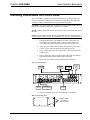
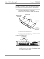
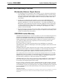
Crestron CNX-ASBK Audio Switcher Bussing Kit Operations & Installation Guide Crestron CNX-ASBK Audio Switcher Bussing Kit Contents Audio Switcher Bussing Kit: CNX-ASBK Description Functional Description Physical Description Identity Codes of the CNX-PAD8s Installing CNX-ASBKs into CNX-PAD8s Industry Compliance Programming Daisy-Chained CNX-PAD8s Problem Solving Troubleshooting Further Inquiries Future Updates Return and Warranty Policies Merchandise Returns / Repair Service CRESTRON Limited Warranty Operations & Installation Guide - DOC. 8143 1 1 1 1 2 3 7 7 8 8 8 8 9 9 9 Contents • i Crestron CNX-ASBK Audio Switcher Bussing Kit Audio Switcher Bussing Kit: CNX-ASBK Description Functional Description The Audio Switcher Bussing Kit, CNX-ASBK, is used to daisy-chain CNX-PAD8s to expand the number of room outputs. Each CNX-PAD8 controls up to eight audio sources and distributes the audio to up to eight room amplifiers (not supplied). A maximum of four CNX-PAD8s may be daisy-chained together to provide up to 32 room outputs. The CNX-ASBK provides for the additional outputs by bussing up to eight inputs while preventing extreme impedance loading. One kit is needed for each CNX-PAD8 that is to be daisy-chained. Physical Description Each CNX-ASBK consists of one Point Cross Loop Printed Circuit Board (PCB) Assembly, eight 4-conductor Cross Point PCB to Processor PCB Cable Assemblies, and four 12-conductor Bussing Cable Assemblies. Refer to the physical views shown after this paragraph. PCB Assembly (Front and Rear View) 8.59" 1.48" 4-PIN CONNECTORS (FRONT VIEW) 12-PIN CONNECTORS (REAR VIEW) PCB MOUNTED STAND-OFFS Operations & Installation Guide - DOC. 8143 Audio Switcher Bussing Kit: CNX-ASBK • 1 Audio Switcher Bussing Kit Crestron CNX-ASBK PCB to PCB Cable (2-inch, 4-conductor) (SIDE VIEW) (BOTTOM VIEW) Bussing Cable (6-inch, 12-conductor) (SIDE VIEW) KEY (BOTTOM VIEW) KEY Identity Codes of the CNX-PAD8s Every equipment and user interface within the network requires a unique identity code (Net ID). These codes are recognized by a two-digit hexadecimal number from 03 to FE. The Net ID of the unit must match an ID code specified in the SIMPL Windows program. The Net ID of CNX-PAD8s is factory set to 44. The Net IDs of each of the daisy-chained CNX-PAD8s must be unique and changed from a PC via VisionToolsTM Pro-e (VT Pro-e) or SIMPL Windows. The method for changing the unit’s Net ID is identical regardless of the software chosen. Verify that the control system software is running and complete the following steps to change the Net ID: 1. Disconnect all network devices from the control system. 2. Attach one of the CNX-PAD8s that needs to have its Net ID changed to the control system. 3. Select Tools | Viewport to open “Crestron Viewport” dialog box. 4. Select Functions | Set Network ID. The software checks the baud rate and then opens the “Set Network ID” dialog box. 5. The list of current network devices is normally shown in the dialog box. Highlight the CNX-PAD8. 6. The Net ID of the CNX-PAD8 (default is 44) appears in the box below the list. Use the scroll arrow to assign another Net ID. 7. When the newly assigned Net ID appears, select the Set ID button to initiate the change. 8. The software responds with a successful message to confirm the new Net ID. 9. To verify this procedure, select Diagnostics | Report Network Devices. Confirm that the CNX-PAD8 has a new Net ID code. 10. Repeat steps 2 - 10 of this procedure for each CNX-PAD8 that needs its Net ID changed. 11. Reconnect other network devices that were disconnected in step 1. 2 • Audio Switcher Bussing Kit: CNX-ASBK Operations & Installation Guide - DOC. 8143 Crestron CNX-ASBK Audio Switcher Bussing Kit Installing CNX-ASBKs into CNX-PAD8s One CNX-ASBK is required for each CNX-PAD8 that is to be daisy-chained. The only tools required are a Phillips tip screwdriver and a grounding strap. Follow the assembly procedure and illustrations that begin after this paragraph. CAUTION: The CNX-PAD8s must be opened to install the CNX-ASBK. Observe precautions for handling electrostatic sensitive devices (ESDs). NOTE: To daisy-chain CNX-PAD8s, all of the units must be stacked directly above the other. NOTE: This procedure assumes that one CNX-PAD8 is already rack mounted in a network system. If this is a totally new installation, start on step 7 of this procedure. 1. If the back panel of the CNX-PAD8 is accessible, remove the rack mounting screws. If the back panel is NOT accessible, remove the screws and pull CNX-PAD8 partially out of the rack to gain access. 2. At the rear of the CNX-PAD8, disconnect the electrical power (4-pin Cresnet power connector and/or the external power pack). 3. Note (or label) the position of each 6-pin RJ-11 network device cable and disconnect. 4. Note (or label) the position of audio output, audio input loop-through, and audio input RCA cables and disconnect each cable. 5. Remove the ground wire from the CNX-PAD8 ground screw. Rear View of CNX-PAD8 CRESNET POWER GROUND SCREW CRESNET G 24 Y 1 - 2 3 - 4 5 - 6 EXTERNAL POWER PACK NETWORK DEVICES Z 24VDC 1A G 7 - 8 SOURCES ROOMS 1 2 3 4 5 6 7 1 8 LEFT LEFT RIGHT RIGHT 2 3 4 5 6 7 8 CRESTRON ELECTRONICS INC. ROCKLEIGH, N.J. 07647 AUDIO INPUT 6. AUDIO INPUT LOOP-THROUGH AUDIO OUTPUT Remove the mounting ears from each side of the CNX-PAD8. Remove the Mounting Ears REMOVE THESE (3) SCREWS FROM EACH SIDE Operations & Installation Guide - DOC. 8143 Audio Switcher Bussing Kit: CNX-ASBK • 3 Audio Switcher Bussing Kit Crestron CNX-ASBK NOTE: The remaining steps of this procedure describe the installation of one CNX-ASBK into one CNX-PAD8. The steps apply to all of the CNX-PAD8s to be daisy-chained and may be performed in an “assembly line” fashion on all of the CNX-PAD8s at the same time. 7. Place the CNX-PAD8 right-side-up on a flat surface. 8. Remove the cover screws from the top and sides of the CNX-PAD8. Remove the Cover Screws REMOVE THREE (3) SIDE SCREWS IF NOT RACK MOUNTED, REMOVE THESE (3) SIDE SCREWS ALSO REMOVE FOUR (4) TOP SCREWS REMOVE THREE (3) SIDE SCREWS IF NOT RACK MOUNTED, REMOVE THESE (3) SIDE SCREWS ALSO 9. Lift and remove the CNX-PAD8 top cover. 10. From the rear of the CNX-PAD8, remove the 10 back panel cover plate mounting screws and remove the cover plate. Back Panel Cover Plate Mounting Screws 10 COVER PLATE MOUNTING SCREWS CRESNET G 24 Y 1 - 2 3 - 4 5 - 6 Z 24VDC 1A G 7 - 8 SOURCES ROOMS 1 2 3 4 5 6 7 1 8 LEFT LEFT RIGHT RIGHT 2 3 4 5 6 7 8 CRESTRON ELECTRONICS INC. ROCKLEIGH, N.J. 07647 11. Making sure that the rear of the PCB assembly faces the rear of the CNX-PAD8, insert the PCB into the position that was occupied by the back panel cover plate as shown after this step. Install the PCB with the 10 cover plate screws that were removed. 4 • Audio Switcher Bussing Kit: CNX-ASBK Operations & Installation Guide - DOC. 8143 Crestron CNX-ASBK Audio Switcher Bussing Kit Install the PCB Assembly 10 COVER PLATE SCREWS NOTE: DO NOT twist the cables during installation. The cables are custom designed and will fit perfectly. If the cable does not fit correctly, switch the cable ends from the PCB to the CNX-PAD8 processor PCB. DO NOT force the connector onto pins. 12. Hold one end of the PCB to PCB cable (2-inch, 4-pin) toward the front of the CNX-PAD8. Carefully align and insert the other connector onto the connector on CNX-PAD8 processor PCB. 13. Curl the cable directly above and insert the other connector onto the pins of the PCB as shown. Install the PCB to PCB Cables Operations & Installation Guide - DOC. 8143 Audio Switcher Bussing Kit: CNX-ASBK • 5 Audio Switcher Bussing Kit Crestron CNX-ASBK 14. Repeat the previous two steps for all of the remaining PCB to PCB cables. 15. Install the rack mounting ears and then the remaining cover screws to 11-inch/pounds. Install the CNX-PAD8 Cover INSTALL THREE (3) SIDE SCREWS IF NOT RACK MOUNTED, INSTALL THESE (3) SIDE SCREWS ALSO INSTALL FOUR (4) TOP SCREWS INSTALL THREE (3) SIDE SCREWS IF NOT RACK MOUNTED, INSTALL THESE (3) SIDE SCREWS ALSO 16. If this procedure has been performed on only one CNX-PAD8, repeat this procedure from step 7 for all of the CNX-PAD8s to be daisychained. 17. If the back panels of the CNX-PAD8s will be accessible when mounted in the rack, install the CNX-PAD8s. If the back panels will NOT be accessible, hookup all cables before installing into rack. NOTE: DO NOT twist the cables during installation. The cables are custom designed and will fit perfectly. If the cable does not fit correctly, switch the cable ends from one CNX-PAD8 to another. DO NOT force the connector onto pins. 18. Note the position of the connector keys and install the bussing cables (6-inch, 12-conductor) from CNX-PAD8 to CNX-PAD8. Shown below are the bussing cables for audio sources 1 – 2. Connect the cables as required per custom installation. Install the Bussing Cables 12-PIN, 6-INCH CABLE TO CNX-PAD8 ABOVE, IF APPLICABLE CRESNET G 24 Y 1 - 2 3 - 4 5 - 6 Z 24VDC 1A G 7 - 8 SOURCES ROOMS 1 2 3 4 5 6 7 LEFT 2 3 4 5 6 7 8 LEFT RIGHT CRESTRON ELEC 1 8 RIGHT S INC. ROCKLEIGH, N.J. 07647 12-PIN, 6-INCH CABLE TO CNX-PAD8 BELOW, IF APPLICABLE NOTE POSITION OF CONNECTOR KEY 6 • Audio Switcher Bussing Kit: CNX-ASBK Operations & Installation Guide - DOC. 8143 Crestron CNX-ASBK Audio Switcher Bussing Kit 19. Daisy-chain the ground wire to each CNX-PAD8. NOTE: Additional audio patch cords are not required. The bussing cables provide parallel audio inputs to all of the CNX-PAD8s. 20. Connect the audio RCA cables to the audio inputs and/or audio input loop-through into their original positions of the original or “primary” CNX-PAD8. 21. If the configuration of the original CNX-PAD room outputs is to be kept, reconnect the audio output cables to their original positions. Connect the audio outputs of the each CNX-PAD8 to their designated room amplifiers. 22. Connect each 6-pin RJ-11 network device cable to its original position. 23. Using network device cables (not supplied), daisy-chain each CNX-PAD8 to each other or the control system. 24. At the rear of the CNX-PAD8s, connect the electrical power (4-pin Cresnet power connectors and/or the external power packs). Industry Compliance As of the date of manufacture, this unit has been tested and found to comply with specifications for CE marking and standards per EMC and Radiocommunications Compliance Labelling. Programming Daisy-Chained CNX-PAD8s The CNX-PAD8s can be programmed to fit any customized installation. Daisychained CNX-PAD8s are programmed individually by using their unique Net IDs. Refer to the CNX-PAD8 Operations Guide (latest revision of Doc. 8137) for further information. Operations & Installation Guide - DOC. 8143 Audio Switcher Bussing Kit: CNX-ASBK • 7 Audio Switcher Bussing Kit Crestron CNX-ASBK Problem Solving Troubleshooting The table below provides corrective action for possible trouble situations of the daisy-chained CNX-PAD8s. If further assistance is required, refer to the CNX-PAD8 Operations Guide or please contact a Crestron customer service representative. Daisy-Chained CNX-PAD8 Troubleshooting TROUBLE POSSIBLE CAUSE(S) CORRECTIVE ACTION No audio at all CNX- Audio source cables PAD8s. not connected. Verify that audio source cables plugged into original or "primary" CNXPAD8 are secure. One or more (but not Bussing cable(s) or Check pins and temporarily swap all) CNX-PAD8s not pin(s) damaged or not bussing cable(s). Replace cable(s) if distributing audio. connected properly. damaged. PCB to PCB cable(s) or Check pins and temporarily swap PCB pin(s) damaged or not to PCB cable(s). Replace cable(s) if connected properly. damaged. Yellow NET LED on Improper NET ID. Verify that CNX-PAD8 NET ID the front panel of a matches NET ID software program. daisy-chained CNXRefer to "Identity Codes of the CNXPAD8 does not PAD8s". illuminate. Further Inquiries If you cannot locate specific information or have questions after reviewing this guide, please take advantage of Crestron's award winning customer service team by calling the Crestron corporate headquarters at 1-888-CRESTRON [1-888-273-7876]. For assistance in your local time zone, refer to the Crestron website (www.crestron.com) for a listing of Crestron worldwide offices. You can also log onto the online section of the Crestron website (www.crestron.com) to ask questions about Crestron products. First-time users will need to establish a user account to fully benefit from all available features. Future Updates As Crestron adds improvements to the CNX-ASBK, additional information may be made available as manual updates. These updates are solely electronic and serve as intermediary supplements prior to the release of a complete technical documentation revision. Check the Crestron website (www.crestron.com) periodically for manual update availability and its relevance. Updates are available from the Download | Product Manuals section and are identified as an “Addendum” in the Download column. 8 • Audio Switcher Bussing Kit: CNX-ASBK Operations & Installation Guide - DOC. 8143 Crestron CNX-ASBK Audio Switcher Bussing Kit Return and Warranty Policies Merchandise Returns / Repair Service 1. No merchandise may be returned for credit, exchange, or service without prior authorization from CRESTRON. To obtain warranty service for CRESTRON products, contact the factory and request an RMA (Return Merchandise Authorization) number. Enclose a note specifying the nature of the problem, name and phone number of contact person, RMA number, and return address. 2. Products may be returned for credit, exchange, or service with a CRESTRON Return Merchandise Authorization (RMA) number. Authorized returns must be shipped freight prepaid to CRESTRON, 6 Volvo Drive, Rockleigh, N.J., or its authorized subsidiaries, with RMA number clearly marked on the outside of all cartons. Shipments arriving freight collect or without an RMA number shall be subject to refusal. CRESTRON reserves the right in its sole and absolute discretion to charge a 15% restocking fee, plus shipping costs, on any products returned with an RMA. 3. Return freight charges following repair of items under warranty shall be paid by CRESTRON, shipping by standard ground carrier. In the event repairs are found to be non-warranty, return freight costs shall be paid by the purchaser. CRESTRON Limited Warranty CRESTRON ELECTRONICS, Inc. warrants its products to be free from manufacturing defects in materials and workmanship under normal use for a period of three (3) years from the date of purchase from CRESTRON, with the following exceptions: disk drives and any other moving or rotating mechanical parts, pan/tilt heads and power supplies are covered for a period of one (1) year; touchscreen display and overlay components are covered for 90 days; batteries and incandescent lamps are not covered. This warranty extends to products purchased directly from CRESTRON or an authorized CRESTRON dealer. Purchasers should inquire of the dealer regarding the nature and extent of the dealer's warranty, if any. CRESTRON shall not be liable to honor the terms of this warranty if the product has been used in any application other than that for which it was intended, or if it has been subjected to misuse, accidental damage, modification, or improper installation procedures. Furthermore, this warranty does not cover any product that has had the serial number altered, defaced, or removed. This warranty shall be the sole and exclusive remedy to the original purchaser. In no event shall CRESTRON be liable for incidental or consequential damages of any kind (property or economic damages inclusive) arising from the sale or use of this equipment. CRESTRON is not liable for any claim made by a third party or made by the purchaser for a third party. CRESTRON shall, at its option, repair or replace any product found defective, without charge for parts or labor. Repaired or replaced equipment and parts supplied under this warranty shall be covered only by the unexpired portion of the warranty. Except as expressly set forth in this warranty, CRESTRON makes no other warranties, expressed or implied, nor authorizes any other party to offer any warranty, including any implied warranties of merchantability or fitness for a particular purpose. Any implied warranties that may be imposed by law are limited to the terms of this limited warranty. This warranty statement supercedes all previous warranties. Trademark Information All brand names, product names, and trademarks are the sole property of their respective owners. Windows is a registered trademark of Microsoft Corporation. Windows95/98/Me/XP and WindowsNT/2000 are trademarks of Microsoft Corporation. Operations & Installation Guide - DOC. 8143 Audio Switcher Bussing Kit: CNX-ASBK • 9 Crestron Electronics, Inc. 15 Volvo Drive Rockleigh, NJ 07647 Tel: 888.CRESTRON Fax: 201.767.7576 www.crestron.com Operations & Installation Guide – DOC. 8143 07.99 Specifications subject to change without notice.