1
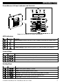
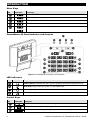
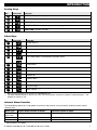
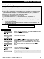
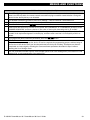
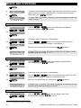
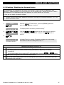
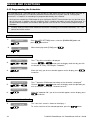
REVIEWING TROUBLES AND ALARM MEMORY
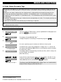
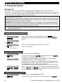
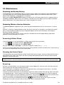
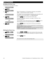
IMPORTANT! If the trouble beeps bother you, disarm the system again (even though it is already disarmed).
This will cancel the trouble beeps for 4 hours.
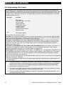
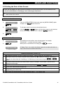
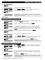
C. Reviewing Memory & Troubles at the Same Time
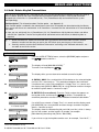
If alarms / tamper events are retained in the alarm memory and at the same time a state of trouble exists, the
display will first read the alarm memory followed by trouble events, as described in sections A & B above.
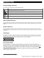
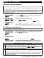
General Indications
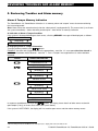
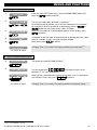
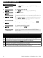
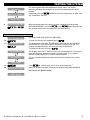
After all trouble messages have been reviewed and if a SIM card is installed in the control panel, the
PowerMaster-10/PowerMaster-30 displays the GSM signal strength indication, as follows: "GSM RSSI
STRONG" / "GSM RSSI GOOD" / "GSM RSSI POOR".
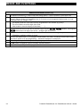
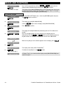
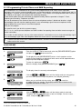
If a PIR camera is enrolled in the system, the control panel will read "GPRS initialize" to indicate that the modem
is undergoing initialization. This message appears at the end of all trouble messages and immediately following
the GSM signal strength indication (if a SIM card is installed).
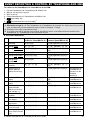
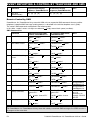
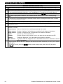
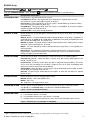
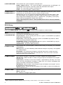
Correcting Trouble Situations
The trouble indications (illuminated TROUBLE indicator and flashing TRBL message) are cleared once you
eliminate the cause of trouble. The table below describes the system faults and respective corrective actions. If
you do not know how to correct a trouble situation, report it to your installer and seek his advice.
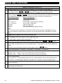
Fault
What it means
1-WAY
The device functions but cannot "hear" the panel. The control panel cannot configure
or control the device. Battery consumption increases.
AC FAILURE
There is no power supplied to the device.
CLEAN ME
The fire detector must be cleaned
COMM. FAILURE
A message could not be sent to the monitoring station or to a private telephone (or a
message was sent but was not acknowledged)
CPU LOW BATTERY
The backup battery within the control panel is weak and must be replaced (see
Chapter 10. Maintenance, "Replacing Backup Battery").
CPU TAMPER
The control panel was physically tampered with or its cover was opened, or it was
removed from wall.
FUSE TROUBLE
The PGM fuse is burnt out or overloaded.
GAS TROUBLE
Gas detector failure
GSM NET FAIL
The GSM communicator is not able to connect to the cellular network.
JAMMING
A radio-frequency signal which is blocking all communication frequency channels
between the sensors and control panel is detected.
LOW BATTERY
The battery of the indicated device is near the end of its useful life.
MISSING
A device or detector has not reported for some time to the control panel.
NOT NETWORKED
A device was not installed or not installed correctly, or, cannot establish
communication with the control panel after installation.
RSSI LOW
The GSM communicator has detected that GSM network signal is weak
SIREN AC FAILURE
There is no power to the siren
LINE FAILURE
There is a problem with the telephone line
24
D-303223 PowerMaster-10 / PowerMaster-30 User's Guide