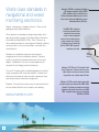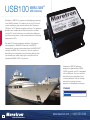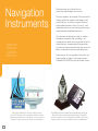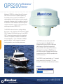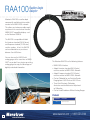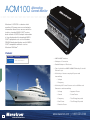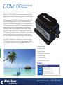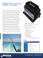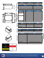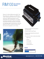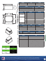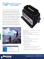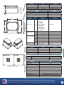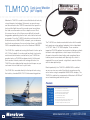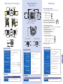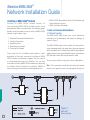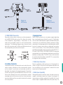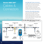
1
PRODUCT CATALOG 2010
2010
www.maretron.com
Contents
2010
PRODUCT
PC Software/Interfacing
Displays & Alarms
CATALOG
Maretron designs, manufactures and markets leadingedge networked electronics for the marine marketplace.
Maretron’s products are designed to the open industry
NMEA 2000® standard, which allows electronic equipment
from diverse manufacturers to be networked together for
sharing information throughout the vessel. Maretron’s
corporate philosophy is to provide premium quality,
state-of-the-art marine electronics that work in conjunction
with traditional navigation techniques for the highest level of
safety and performance while boating.
Navigation Instruments
Engine/Vessel Monitoring
Cables and Connectors
Network Installation Guide
866-550-9100
World-class standards in
navigational and vessel
monitoring electronics.
Simpler, safer boating. Freedom of choice. Those are the
guiding principles behind Maretron.
All the products we develop are designed to perform in the
open plug-and-play network, the National Marine Electronics
Association standard (NMEA 2000®). Why? Because no
other network provides the same degree of flexibility, allowing
you to buy best-in-class instrumentation – no matter who
manufactures it.
Maretron was founded by engineers who designed
integrated circuits for the automotive industry. No other
industry has perfected networked electronics to the same
degree. Avid boaters, they saw a unique opportunity to
transport this technology to marine electronics.
The result? A growing line of networked products that install
simply and perform with increased reliability. Products that
allow you the freedom of choice to select components from
your favorite brands of electronic components.
Maretron. We may be the newest name in marine electronics,
but we intend to lead the way to simpler, safer boating.
www.maretron.com
4
Maretron’s USB100 is a gateway for bridging
USB equipped computers with the NMEA
2000® network so you can continue to use
PC-based navigation software or you can view
critical vessel systems using Maretron’s vessel
monitoring software (N2KView).
The NMEA 2000 standard is
a serial data communications
network for interconnecting
marine electronic equipment
where all data is transferred over
a single network cable. Maretron
is leading the way by introducing
the first “NMEA 2000® Approved”
connectors and cables.
®
Trunk
Termination
Resistor
Maretron’s DST100 Smart™ Retractable Depth/
Speed/Temperature Transducer delivers precise
digital depth, accurate speed and exact water
temperature even at speeds above 40 knots.
Maretron’s TLA100 is used to adapt commercially
available resistive tank senders to the NMEA 2000®
network. This allows you to observe tank levels
anywhere on the vessel where there is an NMEA
2000® compatible display such as the Maretron
DSM200 or DSM250.
Maretron’s SSC200 is a solid state
rate gyro compass with no moving
parts and, unlike a flux gate compass
that sloshes around during turns
or pitching seaways, the SSC200
continues to provide accurate heading
information. The result is increased
fuel economy and reduced wear and
tear on your autopilot since S-turning
about the desired course is reduced.
Maretron’s color
(DSM250) display is a 5.7”
easy to use display
for monitoring any or all
NMEA 2000 network data
including engine gauges,
navigational information,
environmental data, tank
levels, and much more.
®
Maretron’s WSO100 is an
ultrasonic wind and weather
station that measures wind speed
and direction, air temperature,
barometric pressure, and relative
humidity. The wind measurement
is performed using ultrasonic
sensors, which means there are
no moving parts to wear out or to
get caught in the rigging.
Wind
Transducer
Maretron’s GPS200 is a global
positioning system antenna/
receiver that incorporates the
latest WAAS technology for
accurate position fixes. The
GPS200 connects directly to
an NMEA 2000® network and
communicates with navigational
software, chart plotters,
autopilots and dedicated
instrument displays and its
compact, waterproof housing
provides years of reliable
performance.
Display
Radar
NMEA 2000
to/from
USB
Gateway
Maretron products include
engine monitors for
converting newer digital
engine data as well as
analog engine data to an
NMEA 2000® format so
the data can be observed
anywhere on the vessel with
any NMEA 2000® compatible
display.
GPS
Computer
Compass
Depth/Speed/Temperature
Transducer
Engine
Monitoring
Trunk
Termination
Resistor
Tank Level
Adapter
Battery
Rudder Angle
Adapter
Network topology includes
simple tee connections (or
drops) where devices can be
connected or disconnected
from the trunk line under
power without disturbing the
rest of the network.
Single network cable
provides power as well
as communication
signals which eliminates
the need for separate
power connections.
Maretron’s RAA100 is used to adapt
commercially available resistive rudder
angle senders to the NMEA 2000®
network. This allows you to observe rudder
angle anywhere on the vessel where there
is an NMEA 2000® compatible display
such as the Maretron DSM200 or DSM250.
Cable connector ends are
nickel-plated brass to withstand
the harsh marine environment
and are keyed for error-free
connections. Screw thread
connector ends reduce chances
of accidental disconnects
of essential equipment. All
connections are waterproof and
continue to work even while
they are submerged in the bilge.
PC Software/
Interfacing
• N2KView®
• USB100
6
Maretron brings world-class vessel
monitoring systems to the PC using state of
the art networking technology. Now you can
monitor all critical vessel systems including
engines, gensets, tanks, rudder, navigation
instruments, local weather, electrical systems
and more, all using an open industry standard
for true plug-and-play compatibility.
Maretron’s vessel monitoring and control* software
(N2KView®) provides unprecedented access to all your
vessel’s systems through multiple configurable screens.
*Control refers to specific electrical distributed power
systems that are based on NMEA 2000® networking.
Maretron’s USB gateway (USB100) bridges the gap between an
NMEA 2000® network and a PC using one simple USB connection.
7
N2KView
®
N2KView® is completely user-configurable and you are free
to design different screens to your exact needs while easily
switching from screen to screen for monitoring all your
systems. Digital displays, analog gauges, graphic displays,
warning lights, bar graphs, all can be configured exactly
how you want them to be. You can even set the operating
limits and color bands for analog gauges so you know
when things are within limits and when they are not.
Vessel Monitoring
and Control Software
Whether you are interested in monitoring your
vessel’s systems while underway or remotely from
your home or office, Maretron’s N2KView® software
displays the information you need including
engines, gensets, tanks, rudders, navigation
instruments, local weather, electrical
systems and more.
Once you connect a PC to the NMEA 2000® network
using the Maretron USB100 gateway, you can connect
other PCs or handhelds using conventional technology
like Ethernet or Wi-Fi for remote viewing of things like
tank levels up on deck while fueling, or for monitoring the
vessel’s location anywhere in the world using an Internet
connection back to the boat.
Engine
View
8
Electrical
Systems View
www.maretron.com 1-866-550-9100
Navigation
View
Environmental
View
Windows PC Server/Client System Requirements
Parameter
Operating System
CPU Minimum
CPU Recommended
Memory Minimum
Memory Recommended
Hard Drive Space
CD-ROM or DVD Drive
Value
Latest Service Pack may be Required for Support
Vista
Latest Service Pack may be Required for Support
Pentium® 4 or Equivalent
Pentium® 4, (3.0 GHz)
512 MB RAM
1 GB RAM
40 MB
Single
Video Card Minimum
128 MB
Video Card Recommended
256 MB
USB Ports
Two USB Ports – 1.1 or 2.0 Compatible
Ethernet Port
Required to Load Software
Products
One Port for Software License Key, One for Maretron Gateway
10BASE-T or 100BASE-TX, or 802.11a/b/g Only Required for Remote Monitoring
Display
1024x768 Resolution, 32-bit Color Video
Multiple Monitor Support
Dedicated Video Cards 64 MB RAM per
Certification
Comment
Windows XP Home Edition/Professional
NMEA 2000® Standard
Approved
PART NUMBER
N2KView-SC
N2KView-C
N2KView-SCP
N2KView-CP
DESCRIPTION
N2KView Basic Software
N2KView Basic Software (Additional Station)
N2KView Platinum Software
N2KView Platinum Software (Additional Station)
Copyright 2009 Maretron, LLP. All rights reserved. As Maretron is constantly improving its products, all specifications are subject to change without notice. Maretron’s products are designed to
be accurate and reliable; however, they should be used only as aids to navigation and vessel monitoring, and not as a replacement for traditional navigation and vessel monitoring techniques. A
prudent captain or navigator never relies on a single source for navigation or system monitoring information. “NMEA 2000” is a registered trademark of the National Marine Electronics Association.
9
USB100
NMEA 2000 ®
USB Gateway
Maretron’s USB100 is a gateway for bridging computers
to an NMEA network. This allows you to use PC based
vessel monitoring and control software like Maretron’s
N2KView® or PC based navigation software. The gateway
provides one simple connection between the network
and the PC, which eliminates conventional multiplexers
and the maze of wires usually associated with interfacing
equipment to PCs.
For older PC based navigation software that requires
receiving data in NMEA 0183 format, the USB100
automatically converts information from the NMEA 2000®
network to NMEA 0183 sentences. You can continue
benefiting from navigational and charting software that
you already own while enjoying the many benefits of
networked NMEA 2000® instruments.
Maretron’s USB100 gateway
bridges the gap between NMEA
2000® networks and PCs equipped
with a USB port. You can continue
benefiting from navigational and
charting software that you already
own while enjoying the many
benefits of networked instruments.
Products
10
PART NUMBER
USB100-01
DESCRIPTION
Gateway NMEA 2000® / USB
www.maretron.com 1-866-550-9100
Specifications
35mm
1.38”
Parameter
Value
NMEA 2000® Connector
NMEA 2000® / USB Isolation
Translated Data Types
Electrical (NMEA 2000® to NMEA 0183) Certifications
79mm
3.11”
USB Connector
USB Type B
USB Supported Signals
D+, D-, +5V, GND
USB Auxiliary Power
+5 Volts < 50 mA
Mechanical
Bi-directional Gateway
Full Speed USB Data Rate
NMEA 0183
With Maretron-Supplied Windows® Drivers
Native NMEA 2000®
With Maretron-Supplied API
Standard
Comment
NMEA 2000® Standard
Level A
Maritime Navigation and Radio Communication Equipment & Systems
IEC 61162-3
Maritime Navigation and Radio Communication Equipment & Systems
IEC 60945
FCC and CE mark
Electromagnetic Compatibility
88mm
3.46”
Type
Data Types
Battery Monitor
Voltage, Current, Temperature
Compass
Vessel Heading, Attitude, Rate of Turn
Depth
Water Depth, Transducer Offset
Engine
Standard Sentences: RPM. Proprietary Sentences: Boost Pressure, Tilt/Trim,Oil Pressure, Oil Temperature,
Coolant Temperature, Alternator Potential, Fuel Rate, Total Engine Hours, Coolant Pressure, Fuel Pressure
GPS
COG, SOG, DOP, Position, Satellites, Time, Date
Rudder Indicator
3.11”
Rudder
Position
Speed
Distance Log, Speed
Weather Station
Water Temperature
Wind
Wind Direction and Speed
79mm
Parameter
Value
Operating Voltage
9 to 16 Volts
Power Consumption
< 150mA
Load Equivalence Number (LEN)
3
Reverse Battery Protection
35mm Yes
1.38”
Load Dump Protection
Yes
Parameter
Average Current Drain
NMEA 2000® Spec. (1 LEN = 50mA)
Indefinitely
Energy Rated Per SAE J1113
Comment
3.11” x 3.46” x 1.38” (79mm x 88mm x 35mm)
Weight
62.23mm
2.45”
Value
Exposed
Degree of Protection
IP67
Operating Temperature
-25°C to 55°C
Storage Temperature
88mm
3.46”
Humidity
Vibration
-40°C to 70°C
93%RH @40° per IEC60945-8.2
2-13.2Hz @ ±1mm, 13.2-100Hz @ 7m/s2 per IEC 60945-8.7
Rain and Spray
12.5mm Nozzle @ 100liters/min from 3m for 30min per IEC 60945-8.8
Solar Radiation
Ultraviolet B, A, Visible, and Infrared per IEC 60945-8.10
Corrosion (Salt Mist)
4 times 7days @ 40°C, 95%RH after 2 hour Salt Spray Per IEC 60945-8.12
Electromagnetic Immunity
Safety Precautions
Including Flanges for Mounting
8 oz. (227 g)
Parameter
76.2mm
3.0”
Relative
Comment
DC Voltage
Value
Size
IEC 60945 Classification
Environmental
Industry Standard Waterproof
Up to 12 Mb/s
62.23mm
2.45”
76.2mm
3.0” Instrument
35mm
1.38”
No Electrical Connection Across Bridge
USB 1.1
USB Interface Modes
88mm
3.46”
76.2mm
3.0”
Industry Standard Waterproof
Opto-Isolated
USB Standard
USB Baud Rate
62.23mm
2.45”
Comment
DeviceNet Micro-C
Conducted, Radiated, Supply, and ESD per IEC 60945-10
79mm
3.11”
Dangerous Voltage, Electromagnetic Radio Frequency per IEC 60945-12
Copyright 2009 Maretron, LLP. All rights reserved. As Maretron is constantly improving its products, all specifications are subject to change without notice. Maretron’s products are designed to be accurate and
reliable; however, they should be used only as aids to navigation and vessel monitoring, and not as a replacement for traditional navigation and vessel monitoring techniques. A prudent captain or navigator never
relies on a single source for navigation or system monitoring information. “NMEA 2000” is a registered trademark of the National Marine Electronics Association.
11
Displays
& Alarms
Maretron offers a multi-function color display that can be used at multiple
locations throughout the vessel. The universal display delivers the information
you need, when and where you need it. The DSM250 is a high-resolution
LCD screen that is readable in bright sunlight and waterproof to IP67 rating.
It displays provide a wide array of information including AC power, battery,
depth, engine, environment, fuel management, GPS, heading, navigation,
rudder, speed, tanks, time, transmission, weather, wind and more.
Maretron’s DSM250 is completely user configurable and you can scroll from
screen to screen automatically or with a single push of a button. Pictured to
the right are just a few of the many possible screen configurations.
• DSM250
• ALM100
12
Also provided as a user interface to the NMEA 2000® network is the
Maretron alarm buzzer (ALM100). A super loud buzzer for alerting you to
alarm conditions. The buzzer is waterproof so it can be mounted outdoors as
well as indoors, and it includes a baffle to reduce noise in confined spaces.
Barometric Pressure Graph
Dual SOG and COG
Course Up Heading
GPS Status
Quad Numeric
Rudder Angle
Moon Phase
Rolling Road
Single Tachometer
Tri-Display
Single Numeric Depth
Local Weather
Quad Engine Gauges
Swing Meter
Single Tank Gauge
Trim Tabs
Wind Speed and Direction
13
DSM250
Maretron’s DSM250 is a high-resolution
sunlight viewable color display that allows
easy interpretation of NMEA 2000® instrument
and navigation data through custom display
configurations, featuring an easy-to-use five-key
illuminated keypad.
Multi-Function
Color Display
Unlike traditional single-display units, DSM250
users can choose numeric, gauge, or graph
formats in single or multiple displays, with
cycling options possible for a wide range of
favorite data. These multiple display options
conserve mounting space and reduce overall
system cost.
The DSM250 will directly connect with any
NMEA 2000® network and display any or all
information captured throughout the vessel.
Various audio and visual alarms are also
programmable.
The DSM250 displays a multitude of information
including AC power, battery, depth, engine,
environment, fuel management, GPS, heading,
navigation, rudder, speed, tanks, time,
transmission, weather, wind and more.
Maretron’s DSM250 is engineered and
manufactured to the highest standards
(IEC 60945 Maritime Navigation and Radio
communication Equipment). Its compact
waterproof housing will provide years of reliable
performance. The DSM250 is available in three
different color cases: black, gray, or white.
Products
14
PART NUMBER
DSM250-01
DSM250-02
DSM250-03
DSMMNTASSBLY
DSM250CVR2PK-01
DSM250CVR2PK-02
DSM250CVR2PK-03
DESCRIPTION
High Bright Color Display (Black Enclosure) High Bright Color Display (Gray Enclosure)
High Bright Color Display (White Enclosure)
DSM200/DSM250 Gimbal Mount
Package of (2) Black DSM250 Covers
Package of (2) Gray DSM250 Covers
Package of (2) White DSM250 Covers
www.maretron.com 1-866-550-9100
Specifications
Parameter
Value
NMEA 2000® Connector
Active Matrix TFT LCD
Sunlight Readable
Display Resolution
320 x 240 Pixels
QVGA Resolution
Display Viewable Area
117mm W x 88mm H
Display Backlighting
Keyboard
Certifications
Supported Data Display Types
3-User-Programmed Levels 0-100%
5 Silicone Rubber Keys
Multi-Colored LED Backlighting
English, Dutch (Nederlands)
User Selectable
Standard
Comment
NMEA 2000® Standard
Level A
Maritime Navigation and Radio Communication Equipment & Systems
IEC 61162-3
Maritime Navigation and Radio Communication Equipment & Systems
IEC 60945
FCC and CE mark
Electromagnetic Compatibility
Data Types
AC Power
Voltage, Current, Frequency, Line-Neutral Voltage, Line-Line Voltage, Real Power, Reactive Power,
Apparent Power, Power Factor, kWH Import, kWH Export
Battery
Voltage, Current, Temperature, State of Charge, State of Health, Time Remaining, Ripple Voltage, Power
Depth
Water Depth, Transducer Offset
Engine Monitor
Tach., Eng. Hrs., Oil, Coolant, Boost & Fuel Pres., Voltage, Oil & Coolant Temp., Fuel Rate, Tilt/Trim
Environment
Barometer, Heat Index, Hum. Inside & Outside, Moon Phase, Sunrise, Sunset, Temp. Dew Point, Temp.
Eng. Room, Temp. Inside, Temp. Sea, Twilight AM & PM, Wind Chill
Fuel Management
Total Fuel Rate,Total Fuel Economy, Total Fuel Remaining
GPS
COG, SOG, DOP, Position, Satellites, Time
Heading
Heading, Rate of Turn, Variation
Navigation
BOD, Drift, Set, XTE, TTG, ETA, VMG, DTW, BTW, Rolling Road, Datum, Waypoint Number & Name,
COG, SOG
Rudder Indicator
Rudder Position and Order
Speed
Through Water, Over Ground, Total Log, Trip Log
Tank Monitor
Capacity, Level, Remaining
Time
Date Local, Date UTC, Time Local, Time UTC
Transmission
Gear, Oil Pressure, Oil Temperature
Trim Tabs
Bar Graph
Wind
Apparent Direction and Speed, True Direction and Speed, Ground Direction and Speed
Parameter
Electrical
5.7” Diagonal
CCFL
Instrument Type
Mechanical
Industry Standard Waterproof
Display Technology
Languages Supported
Value
Operating Voltage
Power Consumption (Maximum)
Comment
9 to 32 Volts
DC Voltage
< 650mA
Low Supply, Full Brightness
< 200mA
Nominal Supply, Low Brightness
Load Equivalence Number (LEN)
13
NMEA 2000® Spec. (1 LEN = 50mA)
Reverse Battery Protection
Yes
Indefinitely
Load Dump Protection
Yes
Energy Rated Per SAE J1113
Parameter
Value
Size
Comment
6.875” x 5.75” x 1.75” (174.6mm x 146mm x 44.5mm)
Weight
Including Flanges for Mounting
26 Oz. (737g)
Mounting
Surface or Flush Mount
Parameter
IEC 60945 Classification
Degree of Protection
Operating Temperature
Environmental
Comment
DeviceNet Micro-C
Storage Temperature
Relative Humidity
Vibration
Rain and Spray
Solar Radiation
Corrosion (Salt Mist)
Value
Exposed
IP67
-25°C to 55°C
-40° to 70°C
93%RH @ 40°C per IEC 60945-8.2
2-13.2Hz @ ±1mm, 13.2-100Hz @ 7m/s² per IEC 60945-8.7
12.5mm Nozzle @ 100liters/min from 3m for 30min per IEC 60945-8.8
Ultraviolet B, A, Visible, and Infrared per IEC 60945-8.10
4 times 7 days @ 40°C, 95%RH after 2 hour Salt Spray per IEC 60945-8.12
Electromagnetic Emission
Conducted and Radiated Emission per IEC60945-9
Electromagnetic Immunity
Conducted, Radiated, Supply, and ESD per IEC 60945-10
Safety Precautions
Dangerous Voltage, Electromagnetic Radio Frequency per IEC 60945-12
Copyright 2009 Maretron, LLP. All rights reserved. As Maretron is constantly improving its products, all specifications are subject to change without notice. Maretron’s products are designed to
be accurate and reliable; however, they should be used only as aids to navigation and vessel monitoring, and not as a replacement for traditional navigation and vessel monitoring techniques. A
prudent captain or navigator never relies on a single source for navigation or system monitoring information. “NMEA 2000” is a registered trademark of the National Marine Electronics Association.
15
ALM100
Alarm
Module
Maretron’s Alarm Module generates visual and audible
alerts for any monitored condition. The Alarm Module
includes an extremely loud 105 dB SPL Piezoelectric
sounder, along with a red high-brightness LED to
indicate an alarm condition. A second green LED
incidates that the Alarm Module is powered and ready
to be triggered. The audible alarm can sound any one
of 32 distinct pre-programmed patterns to indicate
different alerts. The Alarm Module can be triggered
by alarms generated by Maretron’s N2KView® Vessel
Monitoring System, or by Maretron’s DSM250 Color
Graphics Display. The Alarm Module mounts in a
standard electric box or can be flush mounted on any
surface. Completely waterproof, the Alarm Module can
be mounted inside or outside the vessel.
• NMEA 2000® Network Interface
• Super loud 105dB audible alarm
• Bright Red LED visual alarm
• Green LED status indicator
• Mounts in standard electrical wall box or flush
mount directly in wall
• 32 selectable alarm patterns
• Waterproof - Can be mounted indoors or outdoors
Products
16
PART NUMBER
DESCRIPTION
ALM100-01
CP-BK-ALM100
CP-WH-ALM100
Alarm Buzzer with Black Cover Plate
ALM100 Black Cover Plate
ALM100 White Cover Plate
www.maretron.com 1-866-550-9100
Sp
ec
rti
ific
fic
ati
ati
on
on
s
s
Parameter
Comment
105 dB SPL
Annunciator Frequency
Mechanical Volume Control
2.9 kHZ
Standard
Comment
NMEA 2000® Standard
Level A
Maritime Navigation and Radio Communication Equipment & Systems
IEC 61162-3
Maritime Navigation and Radio Communication Equipment & Systems
IEC 60945
FCC and CE mark
Electromagnetic Compatibility
®
NMEA 2000 Parameter
Group Numbers (PGNs)
Ce
4.50" (114mm)
Value
Annunciator Volume
2.75" (70mm)
Description
PGN #
Periodic Data PGNs
Response to Requested PGNs
Protocol PGNs
Maretron Proprietary PGNs
PGN Name
Default Rate
128720 Proprietary Alarm Status*
1 time/second
126464 PGN List (Transmit and Receive)
N/A
126996 Product Information
N/A
126998 Configuration Information
N/A
059392 ISO Acknowledge
N/A
059904 ISO Request
N/A
060928 ISO Address Claim
N/A
065240 ISO Address Command
N/A
126208 NMEA
N/A
128720 Configuration
N/A
*Future firmware updates will allow the ALM100 to be in conformance with the
upcoming NMEA 2000 alarm messaging protocol, once it is defined.
2.204" (56mm)
Electrical
Parameter
Mechanical
2.834" (72mm)
9 to 32 Volts
100 mA
Load Equivalence Number (LEN)
2
Comment
DC Voltage
NMEA 2000 Interface
NMEA 2000® Spec. (1LEN = 50 mA)
Reverse Battery Protection
Yes
Indefinitely
Load Dump Protection
Yes
Energy Rated per SAE J1113
Parameter
Size
Value
Comment
2.75” x 4.50” x 2.00” (70mm x 114mm x 51mm) Including wall plate – Mounts in standard single-gang electrical box
Weight
13 oz. (368.5g)
Parameter
IEC 60945 Classification
Degree of Protection
Environmental
Value
Operating Voltage
Power Consumption
Operating Temperature
Storage Temperature
Relative Humidity
Vibration
Rain and Spray
Solar Radiation
Corrosion (Salt Mist)
Value
Exposed
IP67
-25°C to 55°C
-40°C to 70°C
93%RH @40° per IEC60945-8.2
2-13.2Hz @ ±1mm, 13.2-100Hz @ 7m/s2 per IEC 60945-8.7
12.5mm Nozzle @ 100liters/min from 3m for 30min per IEC 60945-8.8?
Ultraviolet B, A, Visible, and Infrared per IEC 60945-8.10
4 times 7days @ 40°C, 95%RH after 2 hour Salt Spray Per IEC 60945-8.12
Electromagnetic Emission
Conducted and Radiated Emission per IEC 60945-9
Electromagnetic Immunity
Conducted, Radiated, Supply, and ESD per IEC 60945-10
Safety Precautions
Dangerous Voltage, Electromagnetic Radio Frequency per IEC 60945-12
DSM250 Screen Shots
Copyright 2009 Maretron, LLP. All rights reserved. As Maretron is constantly improving its products, all specifications are subject to change without notice. Maretron’s products are designed to
be accurate and reliable; however, they should be used only as aids to navigation and vessel monitoring, and not as a replacement for traditional navigation and vessel monitoring techniques. A
prudent captain or navigator never relies on a single source for navigation or system monitoring information. “NMEA 2000” is a registered trademark of the National Marine Electronics Association.
17
Navigation
Instruments
• WSO100
• SSC200
• GPS200
• DST100
SAIL honors Freeman K. Pittman’s memory with its
annual FKP Awards, which recognize the finest and most
innovative new products on the market—the very stuff that
Freeman sought out during his tenure at the magazine.
18
Maretron brings you state-of-the-art,
award-winning navigation instruments.
Take our compass, for example. We were the first
to bring solid-state compass technology to the
marine industry, resulting in superior accuracy
and incredible response time. The result – rock
solid radar overlay on your charting software and
unprecedented autopilot performance.
Our ultrasonic wind/weather station is another
example of award-winning technology – no
moving parts and built from the ground up for the
marine industry. Aerodynamically designed for
accurate wind speed and direction even when the
boat is heeled over in pitching and rolling seas.
And of course, all our navigation instruments are
engineered to the highest international marine
standard (IEC 60945) for years of reliable service.
The NMMA Innovation Awards are presented each year at the
Miami Boat Show and they recognize products that exhibit
innovative distinction from other products, benefit to the marine
industry and/or consumer, practicality, and cost-effectiveness.
Wind
WSO100 Ultrasonic
and Weather Station
Maretron’s outdoor weather station measures wind speed and
direction, air temperature, barometric pressure, and relative
humidity. The wind measurement is performed using ultrasonic
sensors, which means there are no moving parts to wear out
or to get caught in the rigging.
The WSO100 accurately measures wind speed and direction
even when tilted, making it ideally suited for heeled sailboats
or powerboats operating in pitching and rolling seaways.
When used with Maretron displays (DSM250/N2KView®),
you can view apparent wind speed and direction, humidity,
air temperature, barometric pressure (with graphs to see
trends), wind chill factor, heat index, and dew point. If you add
speed through water (DST100), GPS (GPS100) and compass
(SSC200), you can view true vessel referenced wind speed and
direction as well as ground referenced speed and direction.
The WSO100 provides these functions:
• Apparent Wind Speed
• Apparent Wind Direction
• Atmospheric Pressure
• Air Temperature
• Relative Humidity
Products
20
PART NUMBER
WSO100-01
DESCRIPTION
Ultrasonic Wind/Weather Station
www.maretron.com 1-866-550-9100
Parameter
Value
Wind Speed Range
Specifications
Wind Speed Resolution
88mm
3.45”
0.1 knot (0.19 kph)
Wind Speed Accuracy
Temperature Range
Temperature Resolution
±1.8°F (1°C)
Relative Humidity Range
0-99% RH
Relative Humidity Resolution
1% RH
± 4% RH
± 5% RH
26 to 32” Hg (880 to 1080 mb)
Certifications
Standard
NMEA 2000® Parameter
Group Numbers (PGNs)
Electrical
Mechanical
Level A
IEC 61162-3
Maritime Navigation and Radio Communication Equipment & Systems
IEC 60945
FCC and CE mark
Electromagnetic Compatibility
Periodic Data PGNs
Response to Requested PGNs
Protocol PGNs
PGN #
PGN Name
Default Rate
130306
Wind Data
10 Times/Second
130310
Environmental Parameters
10 Times/Second
130311
Environmental Parameters
2 Times/Second
126464
PGN List (Transmit and Receive)
N/A
126996
Product Information
N/A
126998
Configuration Information
N/A
059392
ISO Acknowledge
N/A
059904
ISO Request
N/A
060416
ISO Transport Protocol, Connection Management
N/A
060160
ISO Transport Protocol, Data Transfer
N/A
060928
ISO Address Claim
N/A
065240
ISO Address Command
N/A
126208
NMEA Complex Request/Command/Ack.
N/A
126720
Configuration
N/A
Parameter
Value
Operating Voltage
9 to 16 Volts
Power Consumption
<150mA
Load Equivalence Number (LEN)
3
Comment
DC Voltage
Average Current Drain
NMEA 2000® Spec. (1LEN = 50 mA)
Reverse Battery Protection
Yes
Indefinitely
Load Dump Protection
Yes
Energy Rated per SAE J1113
Parameter
Value
Size
Weight
Mounting
4.25” Dia. x 3.45” Tall (108mm Dia. x 88mm Tall)
10 oz. (283g)
Pole
Parameter
Degree of Protection
Environmental
Comment
Maritime Navigation and Radio Communication Equipment & Systems
IEC 60945 Classification
DSM250 Screen Shots
±0.1” Hg (±3.4 mb)
NMEA 2000® Standard
Maretron Proprietary PGNs
N2KView Environment Screen
0% to 80% RH
80% to 99% RH
0.03” Hg (1 mb)
Barometric Pressure Accuracy
Description
95.25mm
3.75”
Tilt 0° (operates to 30° tilt)
0.1°F (0.06°C)
Temperature Accuracy
Barometric Pressure Resolution
88.9mm
3.5”
Tilt 0° (operates to 30° tilt)
± 5°
-25° to 55° C
Barometric Pressure Range
108mm
4.25”
± 5% or 1 knot (1.9 kph)
Wind Direction Accuracy
Relative Humidity Accuracy
1” - 14 - UNS-2B Thread
(1” - 14 TPI Standard Marine Mount)
Comment
0.5 to 99.5 knots (1 to 185 kph)
Operating Temperature
Storage Temperature
Relative Humidity
Vibration
Rain and Spray
Solar Radiation
Corrosion (Salt Mist)
Comment
Including Mounting Bracket
Including Mounting Bracket
Fits 1”-14 TPI Standard Marine Mount
Value
Exposed
IP67
-25°C to 55°C
-40°C to 70°C
93%RH @40° per IEC60945-8.2
2-13.2Hz @ ±1mm, 13.2-100Hz @ 7m/s2 per IEC 60945-8.7
12.5mm Nozzle @ 100liters/min from 3m for 30min per IEC 60945-8.8
Ultraviolet B, A, Visible, and Infrared per IEC 60945-8.10
4 times 7days @ 40°C, 95%RH after 2 hour Salt Spray Per IEC 60945-8.12
Electromagnetic Emission
Conducted and Radiated Emission per IEC 60945-9
Electromagnetic Immunity
Conducted, Radiated, Supply, and ESD per IEC 60945-10
Safety Precautions
Dangerous Voltage, Electromagnetic Radio Frequency per IEC 60945-12
Copyright 2009 Maretron, LLP. All rights reserved. As Maretron is constantly improving its products, all specifications are subject to change without notice. Maretron’s products are designed to
be accurate and reliable; however, they should be used only as aids to navigation and vessel monitoring, and not as a replacement for traditional navigation and vessel monitoring techniques. A
prudent captain or navigator never relies on a single source for navigation or system monitoring information. “NMEA 2000” is a registered trademark of the National Marine Electronics Association.
21
SSC200
Solid State
Compass
Maretron’s SSC200 is a solid state, rate
gyro electronic compass that provides
better than 1° heading accuracy through
±45° of roll and pitch angle, and better
than 1° roll and pitch accuracy in static
conditions. Each SSC200 is factory
calibrated for maximum accuracy. It
delivers precise, reliable heading
information ten times per second,
plus vessel attitude including pitch
and roll readings once per second. A
micromachined rate gyro is used by
advanced stabilization algorithms to
provide accurate, stable readings during
dynamically changing conditions such
as hard turns or rough seas, making it
an ideal heading sensor for autopilot
applications.
Maretron’s SSC200 is certified to
the NMEA 2000® network standard
and compatible with the NMEA 0183
digital interface standard. It connects
directly with any NMEA 2000® network
and/or NMEA 0183 listeners to share
information with navigational software,
chart plotters, autopilots, and dedicated
instrument displays – including
Maretron’s DSM250 graphical display.
Products
22
PART NUMBER
SSC200-01
DESCRIPTION
Solid-State Rate/Gyro Compass
The SSC200 can be automatically
calibrated for deviation. Its dynamic
accuracy is improved with advanced
digital filtering of the 3-axis
magnetometer, 2-axis accelerometer
and rate gyro.
The SSC200 is engineered and
manufactured to the highest standards
(IEC 60945 Maritime Navigation and
Radio Communication Equipment).
Its compact waterproof housing will
provide years of reliable performance.
www.maretron.com 1-866-550-9100
Parameter
Value
Static Heading Accuracy
Heading Display Resolution
Specifications
Certifications
NMEA 2000® Parameter
Group Numbers (PGNs)
NMEA 0183
Sentences
To Static Accuracy after 35°/Second Turn
10 per Second
Heading Deviation
Yes
Automatic
Alignment Calibration
Yes
In Boat Calibration with Maretron Displays
Pitch and Roll Range
±80°
With Maretron Display
Pitch and Roll Accuracy
<1°
±45° Pitch and Roll - 15°C to 35°C
Pitch and Roll Display Resolution
0.1°
With Maretron Display
Pitch and Roll Update Rate
Pitch and Roll to Boat Alignment
1 per Second
Yes
In Boat Calibration with Maretron Displays
Rate of Turn Range
0° - 90°/ Second
At 0° Pitch and Roll
Rate of Turn Accuracy
±1° per Second
0° Pitch and Roll - 15°C to 35°C
Rate of Turn Update Rate
10 per Second
Compatible
Up to 38,400 Baud (40 Hz Update Rate)
Standard
Comment
NMEA 2000® Standard
Level A
Maritime Navigation and Radio Communication Equipment & Systems
IEC 61162-3
Maritime Navigation and Radio Communication Equipment & Systems
IEC 60945
FCC and CE mark
Electromagnetic Compatibility
Description
PGN #
Periodic Data PGNs
Protocol PGNs
Sentence
Received
Sentences
127257
Attitude
1 Time/Second
127251
Rate of Turn
10 Times/Second
PGN List (Transmit and Receive)
N/A
126996
Product Information
N/A
126998
Configuration Information
N/A
059392
ISO Acknowledge
N/A
059904
ISO Request
N/A
060416
ISO Transport Protocol, Connection Management
N/A
060160
ISO Transport Protocol, Data Transfer
N/A
060928
ISO Address Claim
N/A
065240
ISO Address Command
N/A
126208
NMEA Request/Command/Acknowledge
N/A
126720
Configuration
Parameter
N/A
Value
9 to 16 Volts
< 150mA
3
Yes
Yes
Value
4.46” x 3.23 x 2.14” (113mm x 82mm x 54mm)
7 Oz. (198 g)
Deck or Bulkhead
IEC 60945 Classification
Degree of Protection
Operating Temperature
Storage Temperature
Relative Humidity
Vibration
Rain and Spray
Solar Radiation
Corrosion (Salt Mist)
Electromagnetic Immunity
Safety Precautions
Description
Heading, Deviation, and Variation
Heading, Magnetic
Heading, True
Rate of Turn
Maretron Proprietary Attitude (Pitch and Roll)
Text Transmission
Recommended Minimum Specific GNSS Data
Course Over Ground and Ground Speed
Parameter
Parameter
10 Times/Second
Sentence Name
Operating Voltage
Power Consumption
Load Equivalence Number (LEN)
Reverse Battery Protection
Load Dump Protection
Size
Weight
Mounting
Default Rate
Vessel Heading
Acronym
HDG
HDM
HDT
ROT
PMAROUT
TXT
RMC
VTG
Transmitted
Sentences
PGN Name
127250
Response to Requested PGNs 126464
Maretron Proprietary PGNs
Environmental Mechanical Electrical
With Maretron Display
1 Second
Heading Update Rate
NMEA 0183 Standard
Copyright 2009 Maretron, LLP. All rights reserved. As Maretron is constantly improving
its products, all specifications are subject to change without notice. Maretron’s products
are designed to be accurate and reliable; however, they should be used only as aids to
navigation and vessel monitoring, and not as a replacement for traditional navigation
and vessel monitoring techniques. A prudent captain or navigator never relies on a single
source for navigation or system monitoring information. “NMEA 2000” is a registered
trademark of the National Marine Electronics Association.
±45° Pitch and Roll - 15°C to 35°C
0.1°
Settling Time
DSM250 Screen Shots
Comment
<1° RMS
10 Times/Second
N/A
N/A
5 Times/Second
1 Time/Second
N/A
N/A
N/A
Comment
DC Voltage
Average Current Drain
NMEA 2000® Spec. (1 LEN = 50mA)
Indefinitely
Energy Rated Per SAE J1113
Comment
Including Mounting Flanges
Including Mounting Bracket
Value
Exposed
IP67
-25°C to 55°C
-40°C to 70°C
93%RH @40° per IEC60945-8.2
2-13.2Hz @ ±1mm, 13.2-100Hz @ 7m/s2 per IEC 60945-8.7
12.5mm Nozzle @ 100liters/min from 3m for 30min per IEC 60945-8.8
Ultraviolet B, A, Visible, and Infrared per IEC 60945-8.10
4 times 7days @ 40°C, 95%RH after 2 hour Salt Spray Per IEC 60945-8.12
Conducted, Radiated, Supply, and ESD per IEC 60945-10
Dangerous Voltage, Electromagnetic Radio Frequency per IEC 60945-12
23
GPS200
GPS Antenna/
Receiver
Maretron’s GPS200 is a state-of-the-art 32 channel
GPS antenna and reciever capable of producing
five position fixes per second. The GPS200 has
unprecedented sensitivity and can even be mounted
underneath a fiberglass deck. An additional benifit of
the GPS200 is that it broadcasts precision magnetic
variation information using the current position and
world magnetic model (WMM-2010).
The GPS200 antenna/receiver is a plug-and-play
device that is fully compliant and certified to the NMEA
2000® Standard. It will directly connect to any NMEA
2000® network and communicate with navigational
software, chart plotters, autopilots and dedicated
instrument displays – such as Maretron’s DSM250
graphical display – and its compact, waterproof
housing provides years of reliable performance.
The GPS200 automatically decodes GPS
correction signals from Satellite Based
Augmentation Systems (SBAS) including the
North American Wide Area Augmentation
System (WAAS), the European Geostationary
Navigation Overlay System (EGNOS), or the
Asian Multifunctional Transport Satellite-based
Augmentation System (MSAS) to provide better
than 2.5m accuracy.
The GPS200 is easily mounted to any 1” standard
marine mount with its standard 1”-14” male
threads. It can also be mounted directly to a deck.
Products
24
PART NUMBER
GPS200-01
DESCRIPTION
GPS Antenna/Receiver
www.maretron.com 1-866-550-9100
Parameter
Value
Position Accuracy (Autonomous)
42mm
1.65”
Position Accuracy (WAAS)
42mm
1.65”
42mm
1.65”
1” - 14 - UNS-2B Thread
(1” - 14 TPI Standard Marine Mount)
Specifications
Channels
Tracking Sensitivity
Comment
<3m
2D RMS (95% of Data Falls Within 10m)
<2.5m
2D RMS (95% of Data Falls Within 3m)
32
Simultaneous Tracking of 32 Satellites
-159dBm
Position Update Rate
5 per Second
Speed Update Rate
4 per Second
Time Update Rate
1 per Second
5 Hz Position Fix Calculation Rate
Hot Start
1 Seconds
Start Within Hours of Last Power Down
Warm Start
33 Seconds
Start Within Days of Last Power Down
Cold Start
36 Seconds
Start from Unknown Position
WAAS
Satellite Based Augmentation System
North America
EGNOS
Europe
MSAS
1” - 14 - UNS-2B Thread
(1” - 14 TPI Standard Marine Mount)
Acceleration Limit
102mm
4.0”
Mechanical Electrical
NMEA 2000® Parameter
Group Numbers (PGNs)
102mm
4.0”
Altitude Limit
<1800m
Velocity Limit
<515 m/sec
20 m/s3
Battery Backup
Lithium (4-5) days
Comment
NMEA 2000® Standard
Maritime Navigation and Radio Communication Equipment & Systems
FCC and CE mark
Description
Periodic Data PGNs
Response to Requested PGNs
Protocol PGNs
PGN #
126992
128259
129025
129026
129029
129539
129540
127258
126464
126996
126998
129538
129541
059392
059904
060416
060160
060928
065240
126206
Parameter
Level A
Tested to IEC 60945
Electromagnetic Compatibility
PGN Name
System Time
Speed
Position, Rapid Update
COG and SOG, Rapid Update
GNSS Position Data
GNSS DOPs
GNSS Satellites in View
Magnetic Variation
PGN List (Transmit and Receive)
Product Information
Configuration Information
GNSS Control Status
GPS Almanac Data
ISO Acknowledge
ISO Request
ISO Transport Protocol, Connection Management
ISO Transport Protocol, Data Transfer
ISO Address Claim
ISO Address Command
NMEA Request/Command/Acknowledge
Value
Operating Voltage
Power Consumption
DC Voltage
<100mA
Load Equivalence Number (LEN)
Default Rate
1 Time/Second
Disabled
5 Times/Second
4 Times/Second
1 Time/Second
1 Time/Second
1 Time/Second
1 Time/Second
N/A
N/A
N/A
N/A
N/A
N/A
N/A
N/A
N/A
N/A
N/A
N/A
Comment
9 to 32 Volts
Average Current Drain
2
NMEA 2000® Spec. (1LEN = 50 mA)
Reverse Battery Protection
Yes
Indefinitely
Load Dump Protection
Yes
Energy Rated per SAE J1113
Parameter
Size
Weight
Mounting
Parameter
Operating Temperature
Storage Temperature
Relative Humidity
Vibration
Rain and Spray
Solar Radiation
Corrosion (Salt Mist)
Electromagnet Emission
Electromagnetic Immunity
Safety Precautions
Value
4” dia. x 1.65”Tall (102mm Dia. X 42mm Tall)
6 Oz. (170 g)
Deck or Pole
Degree of Protection
Environmental
Holds Position for Hot/Warm Starts
Standard
IEC 60954 Classification
DSM250 Screen Shots
Asia
<4g
Jerk Limit
102mm
4.0”
Certifications
1” - 14 - UNS-2B Thread
(1” - 14 TPI Standard Marine Mount)
Comment
Not Including Antenna Mount Base
Not Including Antenna Mount Base
Value
Exposed
IP67
-25°C to 55°C
-40°C to 70°C
93%RH @40° per IEC60945-8.2
2-13.2Hz @ ±1mm, 13.2-100Hz @ 7m/s2 per IEC 60945-8.7
12.5mm Nozzle @ 100liters/min from 3m for 30min per IEC 60945-8.8
Ultraviolet B, A, Visible, and Infrared per IEC 60945-8.10
4 times 7days @ 40°C, 95%RH after 2 hour Salt Spray Per IEC 60945-8.12
Conducted and Radiated Emission per IEC 60945-9
Conducted, Radiated, Supply, and ESD per IEC 60945-10
Dangerous Voltage, Electromagnetic Radio Frequency per IEC 60945-12
Copyright 2009 Maretron, LLP. All rights reserved. As Maretron is constantly improving its products, all specifications are subject to change without notice. Maretron’s products are designed to
be accurate and reliable; however, they should be used only as aids to navigation and vessel monitoring, and not as a replacement for traditional navigation and vessel monitoring techniques. A
prudent captain or navigator never relies on a single source for navigation or system monitoring information. “NMEA 2000” is a registered trademark of the National Marine Electronics Association.
25
DST100
Depth/Speed/
Temperature Transducer
Maretron’s DST100 Smart™
Retractable Depth/ Speed/Temperature
Transducer, delivers precise digital
depth, accurate speed and exact water
temperature even at speeds above 40
knots — all with no programming or
calibration necessary.
Its patented Smart™ Sensor
technology, retractable and removable
sensor, and NMEA 2000® network
connectivity make the DST100 easy to
interpret, easy to install and connect
with other navigation equipment, and
easy to maintain.
The DST100 measures precise water
depth at 0.4m to 60m with a wide beam
width and is tolerant to most deadrise
angles. It reads water temperature from
-10°C to +40°C at ±1.0°C accuracy, and
accurate speed from 1 to 60 knots. At
235kHz it can be used with a fishfinder
as an ideal navigation tool for sport or
commercial fishing vessels—or with
sailing vessels of all sizes.
Products
26
PART NUMBER
DST100-01
M33-100
M33-495-01
33-398-04PW
DESCRIPTION
Depth/Speed/Temperature Triducer®
Bronze Housing Kit for DST100
Stainless Steel Housing Kit for DST100
Spare Paddle Wheel Kit
The DST100’s plastic, bronze, or
stainless steel housing choices are
compatible with any hull material.
It includes a blank plug to replace
its sensor unit when the vessel will
be docked for extended periods or
trailered. This prevents damage
to the sensor and reduces fouling
growth.
Maretron’s DST100 is CE
compliant (IEC 60945) and is
manufactured to the highest
quality standards under ISO9K/2K
procedures. Its compact,
waterproof housing will provide
years of reliable performance,
making it the Smart™ choice in
marine sensing.
www.maretron.com 1-866-550-9100
Parameter
74.7mm (2.94”)
Cable Length 2m
123.7mm
(4.87”)
Bronze
10° x 44°
0.4 meters
Deadrise Angle Tolerant
Maximum Depth
60 meters
No Calibration Required
Depth Tracking Speeds
Up to 40 knots
Depth Update Rate
Certifications
5mm
(0.19”)
Speed Sensor
Paddlewheel
No Calibration Required
Speed Range
1 – 52 knots
Microprocessor Signal Processing Accuracy
Speed Update Rate
1 second
-10°C to 40°C
Water Temperature Accuracy
±1.0°C
Water Temperature Resolution
0.01°C
NMEA 2000® Parameter
Group Numbers (PGNs)
Electrical
Environmental Mechanical
Fast Response Time
No Calibration Required
≤22°
Standard
Comment
NMEA 2000® Standard
Level B+
Maritime Navigation and Radio Communication Equipment & Systems
IEC 61162-3
Maritime Navigation and Radio Communication Equipment & Systems
IEC 60945
FCC and CE mark
Description
DSM250 Screen Shots
High Speed Bottom Tracking Capability
1 second
Deadrise Angle
74.7mm (2.94”)
Wide Beam Angle
Minimum Depth
Water Temperature Range
14mm
(0.57”)
Plastic
Comment
235 kHz
Beam Width
Specifications
2-12” threads
Value
Depth Operating Frequency
Periodic Data PGNs
Response to Requested
PGNs
Protocol PGNs
Electromagnetic Compatibility
PGN#
PGN Name
Water Depth
1 Time/Second
1 Time/Second
128259
Speed (Water Referenced)
130310
Environmental Parameters (Water Temperature) 2 Times/Second
128275
Distance Log
1 Time/Second
126464
PGN List (Transmit and Receive)
N/A
126996
Product Information
N/A
126998
Configuration Information
N/A
059392
ISO Acknowledge
N/A
059904
ISO Request
N/A
060928
ISO Address Claim
N/A
065240
ISO Address Command
N/A
126208
NMEA Request/Command/Acknowledge
N/A
Parameter
Value
Operating Voltage
Parameter
DC Voltage
<50mA
Load Equivalence Number (LEN)
Size
Comment
9 to 16 Volts
Power Consumption
Reverse Battery Protection
Default Rate
128267
Average Current Drain
1
NMEA 2000® Spec. (1LEN = 50 mA)
Yes
Indefinitely
Value
Comment
2.94” Dia. X 4.87” Tall (74.7mm Dia. X 123.7mm Tall)
Weight
Including Mounting Flanges
12 Oz. (340 g)
Mounting
Hole Diameter for Mounting
Parameter
IEC 60945 Classification
Degree of Protection
Lexan/Bronze/Stainless Steel
Bronze/Stainless Steel Optional
2” (51 mm)
Value
Submerged
IP68
Operating Temperature
-10°C to 40°C
Storage Temperature
-40°C to 71°C
Copyright 2009 Maretron, LLP. All rights reserved. As Maretron is constantly improving its products, all specifications are subject to change without notice. Maretron’s products are designed to
be accurate and reliable; however, they should be used only as aids to navigation and vessel monitoring, and not as a replacement for traditional navigation and vessel monitoring techniques. A
prudent captain or navigator never relies on a single source for navigation or system monitoring information. “NMEA 2000” is a registered trademark of the National Marine Electronics Association.
27
Engine /
Vessel
Monitoring
• J2K100
• EMS100
• TLA100
• RAA100
• ACM100
• DCM100
• SIM100
• RIM100
J2K100
J1939 to NMEA 2000® Gateway
EMS100
Analog Engine Monitoring System
TLA100
28
Tank Level Adapter
• TMP100
• TLM100
• TLM150
• TLM200
RAA100
Rudder Angle Adapter
ACM100
Alternating Current Monitor
DCM100
Direct Current Monitor
Maretron brings you plug-and-play engine and
vessel monitoring electronics for distributing
critical data throughout the vessel. Whether
you’re down in the engine room or up at the fly
bridge, all the information you need is available
everywhere you need it.
Gone are the days of disparate systems that fail
to communicate with each other. With Maretron’s
networked electronic components like engine
and tank monitors, vessel data is combined for
advanced features like fuel economy (MPG or
GPM) or distance and time to empty (calculated
from engine fuel rate, vessel speed from GPS,
and fuel remaining from tank monitor).
Finally, true vessel monitoring on a single
network combining information for display
anywhere and everywhere you need it.
SIM100
Switch Indicator Module
RIM100
Run Indicator Module
TMP100
Temperature Module
TLM100
Tank Level Monitor (40”Depth)
TLM150
Tank Level Monitor (Gasoline)
TLM200
Tank Level Monitor (104”Depth)
J2K100
J1939 to NMEA 2000®
Gateway
Maretron’s J2K100 attaches directly into
J1939 networks of compatible engines,
transmissions, and gensets and converts
the J1939 data to the new marine digital
interface (NMEA 2000®). Critical engine,
transmission, and genset data is then
distributed throughout the vessel over a
single cable where it can be monitored by
any NMEA 2000® compatible display.
The J2K100 can also be used as part of a
complete fuel computer. Simply connect the
J2K100 together with Maretron universal
displays (DSM250/N2KView®) and GPS
antenna/receiver (GPS100) and you have
a system capable of displaying gallons per
hour and/or miles per gallon.
Products
M
30
PART NUMBER
J2K100-01
MCF-2M-D4
MCF-2M-D12
MCF-2M-D12CAT
The J2K100 converts the
following information:
• AC Generator Current
• AC Generator Frequency
• AC Generator Voltage
• Tachometer
• Engine Hours
• Coolant Pressure
• Coolant Water Temperature
• Engine Oil Pressure
• Engine Oil Temperature
• Boost Pressure
• Fuel Rate Monitoring
• Charging Voltage
• Percent Engine Load
• Percent Engine Torque
• Rated Engine Speed
• VIN
• Software ID
• Transmission Gear
• Transmission Oil Pressure
• Transmission Oil Temperature
The J2K100 is compatible with
any engine, transmission, or
genset equipped with a J1939
interface, including products
from the following manufacturers:
• Caterpillar
• Cummins
• Detroit Diesel
• John Deere
• Kohler
• Northern Lights
• Onan
• Perkins
• Steyr
• Volvo Penta
• Yanmar
DESCRIPTION
J1939 to NMEA 2000® Gateway
J2K100 adapter Micro female to Deutsche 4 Pin 2 Meter Cordset
J2K100 adapter Micro female to Deutsche 12 Pin 2 Meter Cordset
J2K100 adapter Micro female to Deutsche 12 Pin 2 T cable
www.maretron.com 1-866-550-9100
62.23mm
2.45”
76.2mm
3.0”
76.2mm
3.0”
88mm
3.46”
79mm
3.11”
Specifications (J1939 Data
Translated to NMEA 2000® Data)
62.23mm
2.45”
Certifications
35mm
1.38”
J1939 SPN/PGN
Description
PGN #
NMEA 2000® Parameter
Group Numbers (PGNs)
Periodic Data PGNs
35mm
1.38” 76.2mm
3.0”
79mm
3.11”
Response to Request PGNs
Protocol PGNs
Environmental Mechanical Electrical
Maretron Proprietary PGNs
DSM250 Screen Shots
127488
127488
127489
127489
127489
127489
127489
127489
127489
127489
127489
127489
127498
127498
127498
127493
127493
127493
Standard
88mm
3.46”
62.23mm
2.45”
35mm
1.38”
NMEA 2000® PGN
Engine Speed
Engine Turbocharger Boost Pressure
Engine Oil Pressure
Engine Oil Temperature 1
Engine Coolant Temperature
Alternator Potential (Voltage)
Engine Fuel Rate
Engine Total Hours of Operation
Engine Coolant Pressure
Engine Fuel Delivery Pressure
Engine Percent Load at Current Speed
Actual Engine – Percent Torque
Engine Rated Speed
Vehicle Identification Number
Software Identification
Transmission Current Gear
Transmission Oil Pressure
Transmission Oil Temperature
Comment
NMEA 2000® Standard
Maritime Navigation and Radio Communication Equipment & Systems
Maritime Navigation and Radio Communication Equipment & Systems
FCC and CE mark
79mm
3.11”
N2KView Engine Screen
Description
190 / 61444
102 / 65270
100 / 65263
175 / 65262
110 / 65262
167 / 65271
183 / 65266
247 / 65253
109 / 65263
94 / 65263
92 / 61443
513 / 61444
189 / 65214
237 / 65260
234 / 65242
523 / 61445
127 / 65272
177 / 65272
127488
127489
127498
127493
65030
65226
65227
65228
65229
65230
65231
65232
65234
65235
65236
126464
126996
126998
059392
059904
060928
065240
126208
126720
PGN Name
Engine Parameters, Rapid Update
Engine Parameters, Dynamic
Engine Parameters, Static
Transmission Parameters, Dynamic
J1939 Generator Average Basic AC Quantities
J1939 Diagnostic Message #1
J1939 Diagnostic Message #2
J1939 Diagnostic Message #3
88mm
J1939
Diagnostic Message #4
3.46”
J1939 Diagnostic Message #5
J1939 Diagnostic Message #6
J1939 Diagnostic Message #8
J1939 Diagnostic Message #10
J1939 Diagnostic Message #11
J1939 Diagnostic Message #12
PGN List (Transmit and Receive)
Product Information
Configuration Information
ISO Acknowledge
ISO Request
ISO Address Claim
ISO Address Command
NMEA Request/Command/Acknowledge
Configuration
35mm
1.38”
Parameter
Value
Operating Voltage
Power Consumption
Load Equivalence Number (LEN)
Reverse Battery Protection
Load Dump Protection
Parameter
Size
Weight
Parameter
Value
Default Rate
10 times/second
1 time/second
N/A
10 times/second
10 times/second
N/A
N/A
N/A
N/A
N/A
N/A
N/A
N/A
N/A
N/A
N/A
N/A
N/A
N/A
N/A
N/A
N/A
N/A
N/A
Comment
9 to 16 Volts
<150mA
3
Yes
Yes
3.11” x 3.46” x 1.38” (79mm x 88mm x 35mm)
8 oz. (227 g)
IEC 60945 Classification
Degree of Protection
Operating Temperature
Storage Temperature
Relative Humidity
Vibration
Rain and Spray
Solar Radiation
Corrosion (Salt Mist)
Electromagnetic Emission
Electromagnetic Immunity
Safety Precautions
Level B+
IEC 61162-3
IEC 60945
Electromagnetic Compatibility
DC Voltage
Average Current Drain
NMEA 2000® Spec. (1LEN = 50 mA)
Indefinitely
Energy Rated per SAE J1113
Comment
Including Flanges For Mounting
Value
Exposed
IP67
-25°C to 55°C
-40°C to 70°C
93%RH @40° per IEC60945-8.2
2-13.2Hz @ ±1mm, 13.2-100Hz @ 7m/s2 per IEC 60945-8.7
12.5mm Nozzle @ 100liters/min from 3m for 30min per IEC 60945-8.8
Ultraviolet B, A, Visible, and Infrared per IEC 60945-8.10
4 times 7days @ 40°C, 95%RH after 2 hour Salt Spray Per IEC 60945-8.12
Conducted and Radiated Emission per IEC 60945-9
Conducted, Radiated, Supply, and ESD per IEC 60945-10
Dangerous Voltage, Electromagnetic Radio Frequency per IEC 60945-12
Copyright 2009 Maretron, LLP. All rights reserved. As Maretron is constantly improving its products, all specifications are subject to change without notice. Maretron’s products are designed to
be accurate and reliable; however, they should be used only as aids to navigation and vessel monitoring, and not as a replacement for traditional navigation and vessel monitoring techniques. A
prudent captain or navigator never relies on a single source for navigation or system monitoring information. “NMEA 2000” is a registered trademark of the National Marine Electronics Association.
31
EMS100
Analog Engine
Monitoring System
Maretron’s EMS100 plugs directly
into engine wiring harnesses and
converts analog signals such as water
temperature and oil pressure to the new
marine digital interface (NMEA 2000®).
Critical engine data is then distributed
throughout the vessel over a single
cable where it can be monitored by any
NMEA 2000® compatible display.
The EMS100 is compatible with
existing instrument panels and key
switches so you don’t need to remove
them while upgrading to newer digital
technology. For new installations,
the EMS100 and a compatible
NMEA 2000® display can replace the
traditional analog instrument panel.
32
The EMS100 provides
these functions:
The EMS100 is compatible
with these Yanmar engines
• Tachometer
• Engine Hours
• Coolant Water Temperature
• Engine Oil Pressure
• Boost Pressure
• Charging Voltage
• Drive Trim
• Fuel Filter Alarm
• Boost Alarm
• Coolant Water Level Alarm
• Engine Oil Pressure Alarm
• Exhaust (Salt Water Flow) Alarm
• Coolant Water Temperature Alarm
(other engines supported soon, check
our web page www.maretron.com):
• GM Series
• YM Series
• JH Series
• LH Series
• LP Series
• LY Series
Products
PART NUMBER
EMS100-01
EMSYMR01
DESCRIPTION
Analog Engine Monitoring System
Yanmar Harness
www.maretron.com 1-866-550-9100
Certifications
Specifications
Parameter
127mm
5”
Mechanical
Electrical
114mm
4.5”
Comment
Analog/Digital Input
Configurable by # of Teeth
Engine Hours
Logged with Key On
Stored Indefinitely in Non-Volatile Memory
Oil Pressure
Analog Input
Sensor Voltage Monitor/Sensitize
Coolant Water Temp
Analog Input
Sensor Voltage Monitor/Sensitize
Boost Pressure
Analog Input
Sensor Voltage Monitor/Sensitize
Drive Trim Angle
Analog Input
Sensor Voltage Monitor/Sensitize
Charging Voltage
Alarm/Switch Input
Lube Oil Filter Alarm
Alarm/Switch Input
Boost Pressure Alarm
Alarm/Switch Input
Coolant Water Temperature Alarm
Alarm/Switch Input
Oil Pressure Alarm
Alarm/Switch Input
Exhaust (Salt Water Flow) Alarm
Alarm/Switch Input
Clutch Oil Pressure Alarm
Alarm/Switch Input
Diesel Preheat Alarm
Alarm/Switch Input
Diesel Preheat Alarm
Alarm/Switch Input
Standard
Level A
Maritime Navigation and Radio Communication Equipment & Systems
IEC 60945
FCC and CE mark
Electromagnetic Compatibility
PGN #
Periodic Data PGNs
Response to Request PGNs
Protocol PGNs
Maretron Proprietary PGNs
127488
127489
126464
126996
126998
059392
059904
060416
060160
060928
065240
126208
126720
PGN Name
Default Rate
Engine Parameters, Rapid Update
Engine Parameters, Dynamic
PGN List (Transmit and Receive)
Product Information
Configuration Information
ISO Acknowledge
ISO Request
ISO Transport Protocol, Connection Management
ISO Transport Protocol, Data Transfer
ISO Address Claim
ISO Address Command
NMEA Request/Command/Acknowledge
Configuration
Parameter
Operating Voltage
Power Consumption
Load Equivalence Number (LEN)
10 times/second
1 time/second
N/A
N/A
N/A
N/A
N/A
N/A
N/A
N/A
N/A
N/A
Value
Comment
9 to 16 Volts
NMEA Interface
9 to 32 Volts
Engine Interface
<150mA
From Battery
1
NMEA 2000® Spec. (1LEN = 50 mA)
Reverse Battery Protection
Yes
Indefinitely
Load Dump Protection
Yes
Energy Rated per SAE J1113
Parameter
Size
Value
Comment
5” x 4.5” x 1.25” (127mm x 114mm x 32mm)
Excluding Wiring Harness
12 Oz. (340 g)
Excluding Wiring Harness
Weight
Parameter
Degree of Protection
Environmental
IEC 61162-3
Maritime Navigation and Radio Communication Equipment & Systems
IEC 60945 Classification
DSM250 Screen Shots
Comment
NMEA 2000® Standard
Description
NMEA 2000® Parameter
Group Numbers (PGNs)
32mm
1.25”
Type
Tachometer
Operating Temperature
Storage Temperature
Relative Humidity
Vibration
Rain and Spray
Solar Radiation
Corrosion (Salt Mist)
Value
Exposed
IP68
-25°C to 55°C
-40°C to 70°C
93%RH @40° per IEC60945-8.2
2-13.2Hz @ ±1mm, 13.2-100Hz @ 7m/s2 per IEC 60945-8.7
12.5mm Nozzle @ 100liters/min from 3m for 30min per IEC 60945-8.8
Ultraviolet B, A, Visible, and Infrared per IEC 60945-8.10
4 times 7days @ 40°C, 95%RH after 2 hour Salt Spray Per IEC 60945-8.12
Electromagnetic Emission
Conducted and Radiated Emission per IEC 60945-9
Electromagnetic Immunity
Conducted, Radiated, Supply, and ESD per IEC 60945-10
Safety Precautions
Dangerous Voltage, Electromagnetic Radio Frequency per IEC 60945-12
Copyright 2009 Maretron, LLP. All rights reserved. As Maretron is constantly improving its products, all specifications are subject to change without notice. Maretron’s products are designed to
be accurate and reliable; however, they should be used only as aids to navigation and vessel monitoring, and not as a replacement for traditional navigation and vessel monitoring techniques. A
prudent captain or navigator never relies on a single source for navigation or system monitoring information. “NMEA 2000” is a registered trademark of the National Marine Electronics Association.
33
TLA100
Tank Level
Adapter
The TLA100 is used to adapt
commercially available resistive
tank senders to the NMEA 2000®
network. This allows you to observe
tank levels anywhere on the vessel
where there are NMEA 2000®
compatible displays such as the
Maretron DSM250.
The TLA100 is compatible with both
the American standard (240-30 ohm)
and the European standard (10-180
ohm) resistive senders. In fact, the
TLA100 can be calibrated for any
resistance between 0 and 300 ohms.
Unlike most tank senders that
only work with rectangular tanks,
the TLA100 can be calibrated
for irregular tank shapes so you
know the true level of the tanks.
You can also use the TLA100 with
analog gauges at the same time as
NMEA 2000® so you don’t have to
give up existing analog gauges to
enjoy the advantages of digitally
networked information.
Products
34
PART NUMBER
TLA100-01
DESCRIPTION
Tank Level Adapter
The Maretron TLA100 has the
following features:
•
•
•
•
•
•
•
•
•
•
NMEA 2000® Interface
Adapts American standard (240-30 ohm)
resistive senders to NMEA 2000® Network
Adapts European standard (10-180 ohm) resistive senders to NMEA 2000® Network
Calibrated for any Resistance Range from
0 to 300 Ohms or 300 to 0 Ohms
Accommodates Irregularly Shaped Tanks
with 16 Point Calibration
16 Programmable Tank Types Including
Fuel, Fresh Water, Waste Water, Live Well
Programmable Tank Number(s) Up to 16
per Tank Type
Programmable Tank Capacity
Works Alongside of Analog Gauges
Can be Used Standalone without
Analog Gauges
www.maretron.com 1-866-550-9100
NMEA 2000® Parameter
Group Numbers (PGNs) Certifications
Specifications
Parameter
Value
Comment
Accuracy
+/-2%
Does Not Include Inaccuracies of Analog Gauge or Sender
Resolution
+/-1%
Worst Case (Resolution Better at High Resistance Values)
Number of Tank Types
16
Fuel, Fresh Water, Waste Water, Live Well, Oil, etc.
Number of Tanks per Tank Type
16
16 Tanks per Tank Type Numbered 0-15
American Standard Senders
240-30 ohms
Standard Sender Types are User Selectable
European Standard Senders
10-180 ohms
Standard Sender Types are User Selectable
Calibration Resistance Range
0-300 ohms
Non-Standard Sender Calibration
Support for Irregularly Shaped Tanks
Yes
Can be Calibrated for any Shape Tank
Programmable Tank Capacity
Yes
Allows Displays to Calculate Amount Remaining
Analog Gauge Support
Yes
Can be Used With or Without Analog Gauges
Standard
Comment
NMEA 2000® Standard
Level B+
25mm
1.0”
30mm
1.2”
99mm
3.9”
25mm
1.0”
30mm
1.2”
Maritime Navigation and Radio Communication Equipment & Systems
Maritime Navigation and Radio Communication Equipment & Systems
Electromagnetic Compatibility
Description
PGN #
Periodic Data PGNs
PGN Name
127505
Response to Requested PGNs
Protocol PGNs
Electrical
Mechanical
Default Rate
Fluid Level
0.4 Times/Second
126464
PGN List (Transmit and Receive)
N/A
126996
Product Information
N/A
126998
Configuration Information
N/A
059392
ISO Acknowledge
N/A
059904
ISO Request
N/A
060928
ISO Address Claim
N/A
065240
ISO Address Command
N/A
126208
NMEA Request/Command/Acknowledge
N/A
Value
Operating Voltage
Comment
9 to 16 Volts
Power Consumption
DC Voltage
<100mA
Load Equivalence Number (LEN)
Average Current Drain
2
NMEA 2000® Spec. (1LEN = 50mA)
Reverse Battery Protection
Yes
Indefinitely
Load Dump Protection
Yes
Energy Rated per SAE J1113
Parameter
Size
Value
Comment
3.9” x 1.2” x 1.0” (99mm x 30mm x 25mm)
Weight
Excluding NMEA 2000® Connector & Cable
9 oz. (255g)
Mounting
Parameter
IEC 60945 Classification
Degree of Protection
Operating Temperature
Environmental
IEC 60945
FCC and CE mark
Parameter
DSM250 Screen Shots
IEC 61162-3
Storage Temperature
Relative Humidity
Vibration
Rain and Spray
Solar Radiation
Corrosion (Salt Mist)
Any Orientation
Value
Exposed
IP67
-25°C to 55°C
-40°C to 70°C
93%RH @40° per IEC60945-8.2
2-13.2Hz @ ±1mm, 13.2-100Hz @ 7m/s2 per IEC 60945-8.7
12.5mm Nozzle @ 100liters/min from 3m for 30min per IEC 60945-8.8
Ultraviolet B, A, Visible, and Infrared per IEC 60945-8.10
4 times 7days @ 40°C, 95%RH after 2 hour Salt Spray Per IEC 60945-8.12
Electromagnetic Emission
Conducted and Radiated Emission per IEC 60945-9
Electromagnetic Immunity
Conducted, Radiated, Supply, and ESD per IEC 60945-10
Safety Precautions
Dangerous Voltage, Electromagnetic Radio Frequency per IEC 60945-12
Copyright 2009 Maretron, LLP. All rights reserved. As Maretron is constantly improving its products, all specifications are subject to change without notice. Maretron’s products are designed to
be accurate and reliable; however, they should be used only as aids to navigation and vessel monitoring, and not as a replacement for traditional navigation and vessel monitoring techniques. A
prudent captain or navigator never relies on a single source for navigation or system monitoring information. “NMEA 2000” is a registered trademark of the National Marine Electronics Association.
35
RAA100
Rudder Angle
Adapter
Maretron’s RAA100 is used to adapt
commercially available resistive rudder
senders to the NMEA 2000® network.
This allows you to observe rudder angle
anywhere on the vessel where there are
NMEA 2000® compatible displays such
as the Maretron DSM250.
The RAA100 is compatible with both
the American standard (240-30 ohms)
and European standard (10-180 ohm)
resistive senders. In fact, the RAA100
can be calibrated for any resistance
between 0 and 300 ohms.
You can also use the RAA100 with
analog gauges at the same time as NMEA
2000® so you don’t have to give up existing
analog gauges to enjoy the advantages of
digitally networked information.
The Maretron RAA100 has the following features:
•
•
•
•
•
•
NMEA 2000® Interface
Adapts American standard (240-30 ohm)
resistive senders to NMEA 2000® Network
Adapts European standard (10-180 ohm) resistive senders to NMEA 2000® Network
Can be Calibrated for any Resistive Sender Ranging from 0-300 Ohms or 300-0 Ohms
Three Point Electronic Calibration
eliminates need for Mechanical Adjustment
or Calibration
Can be Used Standalone Without Analog Gauges
Products
36
PART NUMBER
RAA100-01
DESCRIPTION
Rudder Angle Adapter
www.maretron.com 1-866-550-9100
Top View
End View
Side View
Top View
Certifications
Specifications
Parameter
25mm
1.0”
End View
25mm
1.0”
30mm
1.2”
Comment
+/-2%
Does Not Include Inaccuracies of Analog Gauge or Sender
+/-1%
Worst Case (Resolution Better at High Resistance Values)
American Standard Senders
240-30 ohms
Standard Sender Types are User Selectable
European Standard Senders
10-180 ohms
Standard Sender Types are User Selectable
Calibration Resistance Range
0-300 ohms
Non-Standard Sender Calibration
Electronic Calibration
Yes
Eliminates need to mechanically adjust or calibrate
Analog Gauge Support
Yes
Can be Used With or Without Analog Gauges
Standard
Comment
NMEA 2000® Standard
Level B+
Maritime Navigation and Radio Communication Equipment & Systems
Electrical
Mechanical
IEC 60945
FCC and CE mark
Electromagnetic Compatibility
PGN #
PGN Name
Default Rate
Periodic Data PGNs
127254
Rudder
Response to Requested PGNs
126464
PGN List (Transmit and Receive)
N/A
126996
Product Information
N/A
126998
Configuration Information
N/A
059392
ISO Acknowledge
N/A
059904
ISO Request
N/A
060928
ISO Address Claim
N/A
065240
ISO Address Command
N/A
126208
NMEA Request/Command/Acknowledge
N/A
126720
Configuration
N/A
Protocol PGNs
Maretron Proprietary PGNs
10 Times/Second
Value
Operating Voltage
Comment
9 to 16 Volts
Power Consumption
<100mA
Load Equivalence Number (LEN)
2
DC Voltage
Average Current Drain
NMEA 2000® Spec. (1LEN = 50mA)
Reverse Battery Protection
Yes
Indefinitely
Load Dump Protection
Yes
Energy Rated per SAE J1113
Parameter
Value
Comment
3.9” x 1.2” x 1.0” (99mm x 30mm x 25mm)
Size
Weight
Excluding NMEA 2000® Connector & Cable
9 oz. (255g)
Mounting
Any Orientation
Parameter
DSM250 Screen Shots
IEC 61162-3
Maritime Navigation and Radio Communication Equipment & Systems
Parameter
IEC 60945 Classification
Degree of Protection
Operating Temperature
Environmental
99mm
3.9”
NMEA 2000® Parameter
Group Numbers (PGNs)
Side View
Resolution
Description
30mm
1.2”
99mm
3.9”
Value
Accuracy
Storage Temperature
Relative Humidity
Vibration
Rain and Spray
Solar Radiation
Corrosion (Salt Mist)
Value
Exposed
IP67
-25°C to 55°C
-40°C to 70°C
93%RH @40° per IEC60945-8.2
2-13.2Hz @ ±1mm, 13.2-100Hz @ 7m/s2 per IEC 60945-8.7
12.5mm Nozzle @ 100liters/min from 3m for 30min per IEC 60945-8.8
Ultraviolet B, A, Visible, and Infrared per IEC 60945-8.10
4 times 7days @ 40°C, 95%RH after 2 hour Salt Spray Per IEC 60945-8.12
Electromagnetic Emission
Conducted and Radiated Emission per IEC 60945-9
Electromagnetic Immunity
Conducted, Radiated, Supply, and ESD per IEC 60945-10
Safety Precautions
Dangerous Voltage, Electromagnetic Radio Frequency per IEC 60945-12
Copyright 2009 Maretron, LLP. All rights reserved. As Maretron is constantly improving its products, all specifications are subject to change without notice. Maretron’s products are designed to
be accurate and reliable; however, they should be used only as aids to navigation and vessel monitoring, and not as a replacement for traditional navigation and vessel monitoring techniques. A
prudent captain or navigator never relies on a single source for navigation or system monitoring information. “NMEA 2000” is a registered trademark of the National Marine Electronics Association.
37
ACM100
Alternating
Current Monitor
Maretron’s ACM100 is a device which
monitors AC power sources and outputs
information about these sources onto the
industry standard NMEA 2000® marine
data network. ACM100 output information
is then displayed with networked NMEA
2000® equipment such as the Maretron
DSM250 dedicated display or with NMEA
2000® compatible software such as
Maretron N2KView®.
Products
PART NUMBER
ACM100-01
M000630
DESCRIPTION
Alternating Current (AC) Monitor
ACM100 Current Transducer
• NMEA 2000® Interface
• Waterproof Connectors
• Sealed Waterproof Enclosure
• Opto-Isolated from NMEA 2000® Eliminating Potential
Ground Loops
• Monitoring of busses carrying AC power and
transmitting:
- Voltage
- Frequency
• Monitoring AC Power Sources such as Utilities and
Generators and transmitting:
- Voltage
- Apparent Power
- Current
- Power Factor
- Frequency
- Total Energy Imported
- Real Power
- Total Energy Exported
- Reactive Power
38
www.maretron.com 1-866-550-9100
Certific
38.1mm
1.5”
Spe
ations cifications
51.6mm
2.03”
87.63mm
3.45”
Parameter
Measurement Voltage Range
Measurement Voltage Accuracy
Measurement Current Range
Measurement Current Accuracy
Standard
Description
PGN #
65001
65002
65003
65004
65005
65006
65007
65008
65009
65010
106.7mm
4.20”
106.7mm
4.20”
88.9mm
3.50”
Periodic Data PGNs
87.63mm
3.45”
76.2mm
3.0”
51.6mm
2.03”
51.6mm
2.03”
NMEA 2000® Parameter Group Numbers (PGNs)
88.9mm
3.50”
76.2mm
3.0”
38.1mm
1.5”
38.1mm
1.5”
106.7mm
4.20”
Response to Requested PGNs
51.6mm
2.03”
Protocol PGNs
DSM250 Screen Shots
Environmental Mechanical Electrical
Maretron Proprietary PGNs
N2KView Screen
Comment
AC Voltage
0 to 240 VAC
With included current transformer
With included current transformer
Comment
NMEA 2000® Standard
Maritime Navigation and Radio Communication Equipment & Systems
Maritime Navigation and Radio Communication Equipment & Systems
FCC and CE mark
87.63mm
3.45”
76.2mm
3.0”
Value
0 to 240VAC
± 1%
0 to 200A
± 1%
65011
65012
65013
65014
65015
65016
65017
65018
65019
65020
88.9mm
3.50”
65021
65022
65023
65024
65025
65026
65027
65028
65029
65030
126464
126996
126998
38.1mm
1.5”
059392
059904
060928
065240
126208
128720
PGN Name
Value
9 to 32 Volts
100 mA
2
Yes
Yes
Value
3.50” x 4.20” x 2.03” (88.9mm x 106.7mm x 51.6mm)
13 oz. (368.5 g)
Parameter
IEC 60945 Classification
Degree of Protection
Operating Temperature
Storage Temperature
Relative Humidity
Vibration
Solar Radiation
Corrosion (Salt Mist)
Electromagnetic Emission
Electromagnetic Immunity
Safety Precautions
10 times/second
10 times/second
10 times/second
10 times/second
10 times/second
10 times/second
10 times/second
10 times/second
10 times/second
10 times/second
Utility Phase B AC Basic Quantities
Utility Phase A AC Reactive Power
Utility Phase A AC Power
Utility Phase A AC Basic Quantities
Utility Total AC Reactive Power
Utility Total AC Power
Utility Average Basic AC Quantities
Generator Total AC Energy
Generator Phase C AC Reactive Power
Generator Phase C AC Power
Generator Phase C AC Basic Quantities
Generator Phase B AC Reactive Power
Generator Phase B AC Power
Generator Phase B AC Basic Quantities
Generator Phase A AC Reactive Power
Generator Phase A AC Power
Generator Phase A AC Basic Quantities
Generator Total AC Reactive Power
Generator Total AC Power
Generator Average Basic AC Quantities
PGN List (Transmit and Receive)
Product Information
Configuration Information
ISO Acknowledge
ISO Request
ISO Address Claim
ISO Address Command
NMEA
Configuration
Parameter
Parameter
Default Rate
Bus #1 Phase C Basic AC Quantities
Bus #1 Phase B Basic AC Quantities
Bus #1 Phase A Basic AC Quantities
Bus #1 Average Basic AC Quantities
Utility Total AC Energy
Utility Phase C AC Reactive Power
Utility Phase C AC Power
Utility Phase C AC Basic Quantities
Utility Phase B AC Reactive Power
Utility Phase B AC Power
Operating Voltage
Power Consumption
Load Equivalence Number (LEN)
Reverse Battery Protection
Load Dump Protection
Size
Weight
Level A
IEC 61162-3
IEC 60945
Electromagnetic Compatibility
10 times/second
10 times/second
10 times/second
10 times/second
10 times/second
10 times/second
10 times/second
10 times/second
10 times/second
10 times/second
10 times/second
10 times/second
10 times/second
10 times/second
10 times/second
10 times/second
10 times/second
10 times/second
10 times/second
10 times/second
N/A
N/A
N/A
N/A
N/A
N/A
N/A
N/A
N/A
Comment
DC Voltage
NMEA 2000®v Interface
NMEA 2000® Spec. (1LEN = 50 mA)
Indefinitely
Energy Rated per SAE J1113
Comment
Excluding NMEA 2000® Connector & Cable
Value
Exposed
IP64
-25°C to 55°C
-40°C to 70°C
93%RH @40° per IEC60945-8.2
2-13.2Hz @ ±1mm, 13.2-100Hz @ 7m/s2 per IEC 60945-8.7
Ultraviolet B, A, Visible, and Infrared per IEC 60945-8.10
4 times 7days @ 40°C, 95%RH after 2 hour Salt Spray Per IEC 60945-8.12
Conducted and Radiated Emission per IEC 60945-9
Conducted, Radiated, Supply, and ESD per IEC 60945-10
Dangerous Voltage, Electromagnetic Radio Frequency per IEC 60945-12
Copyright 2009 Maretron, LLP. All rights reserved. As Maretron is constantly improving its products, all specifications are subject to change without notice. Maretron’s products are designed to
be accurate and reliable; however, they should be used only as aids to navigation and vessel monitoring, and not as a replacement for traditional navigation and vessel monitoring techniques. A
prudent captain or navigator never relies on a single source for navigation or system monitoring information. “NMEA 2000” is a registered trademark of the National Marine Electronics Association.
39
DCM100
Direct Current
Monitor
Maretron’s DCM100 Monitor is an advanced electronic monitoring
device used to measure the voltage and current of any direct current
(DC) power source or load. Examples of DC power sources that can
be monitored with the DCM100 include batteries, alternators, solar
panels, and wind generators. The DCM100 can also be used to
monitor DC loads like inverters, windlasses, DC refrigerators, or any
DC branch circuit. When the DCM100 is used to monitor batteries,
sophisticated circuitry and software algorithms monitor battery
temperature, load current, charging current and terminal voltage
to precisely compute battery state of charge, state of health, and
time remaining. To measure current, the DCM100 uses an included
state-of-the-art Hall effect current sensor which simply slips over
the wire – you don’t have to break connections or install connectors
as you do with inline shunts used by other solutions. Best of all,
the DCM100 is NMEA 2000® certified so you can view any and all
DC information anywhere on the vessel using a compatible NMEA
2000® display. The DCM100 is a key component of Maretron’s
N2KView® vessel monitoring and control system.
• Battery Voltage
• Battery Current
• Ripple Voltage
• Battery Case Temperature
• State of Charge
• Time Remaining
• Charge Efficiency Factor
Products
40
PART NUMBER
DCM100-01
FC01
LEMHTA200-S
LEMHTA400-S
LEMHTA600-S
TR3K
DESCRIPTION
Direct Current (DC) Monitor
DCM100 Battery Harness with Fuse
200 Amp Current Transducer with Cable
400 Amp Current Transducer with Cable
600 Amp Current Transducer with Cable
DCM100 Ring/Under Bolt Temperature Probe
www.maretron.com 1-866-550-9100
87.63mm
3.45”
87.63mm
3.45”
76.2mm
3.0”
88.9mm
3.50”
76.2mm
3.0”
106.7mm
4.20”
106.7mm
4.20”
Certifications Specifications
38.1mm
1.5”
NMEA 2000® Parameter
Group Numbers
51.6mm
2.03”
Parameter
±100 mV
Battery Current Range
0 to 200A
With included Hall-effect current sensor
±1%
With included Hall-effect current sensor
Battery Current Accuracy
Standard
Level A
Maritime Navigation and Radio Communication Equipment & Systems
Electromagnetic Compatibility
Description
PGN#
Periodic Data PGNs
88.9mm
3.50”
Response to Requested
PGNs
Protocol PGNs
87.63mm
3.45”
Electrical
Mechanical
PGN Name
Default Rate
127506
DC Detailed Status
0.67 times/second
127508
Battery Status
0.67 times/second
127513
Battery Configuration Status
N/A
126464
PGN List (Transmit and Receive)
N/A
126996
Product Information
N/A
126998
Configuration Information
N/A
059392
ISO Acknowledge
N/A
059904
ISO Request
N/A
060928
ISO Address Claim
N/A
065240
ISO Address Command
N/A
126208
NMEA
N/A
128720
Configuration
N/A
88.9mm
3.50”
Parameter
Value
Operating Voltage
Power Consumption
106.7mm
4.20”
Comment
9 to 16 Volts
NMEA Interface
9 to 32 Volts
Battery Interface
70mA, 30mA
VPWR+, VPWR- NMEA 2000 Interface
Load Equivalence Number (LEN)
1
NMEA 2000® Spec. (1 LEN = 50mA)
Reverse Battery Protection
Yes
Indefinitely
Load Dump Protection
Yes
Energy Rated Per SAE J1113
Parameter
Value
Size
Comment
3.50” x 4.20” x 2.03” (88.9mm x 106.7mm x 51.6mm)
Weight
Including Flanges for Mounting
13 oz. (368.5 g)
51.6mm
2.03”
Parameter
Degree of Protection
Environmental
IEC 60945
FCC and CE mark
IEC 60945 Classification
N2KView Systems Screen
IEC 61162-3
Maritime Navigation and Radio Communication Equipment & Systems
38.1mm
1.5”
38.1mm
1.5”
Comment
NMEA 2000® Standard
76.2mm
3.0”
51.6mm
2.03”
Comment
0 to 50 VDC
Battery Sense Voltage Accuracy
Maretron Proprietary PGNs
51.6mm
2.03”
Value
Battery Sense Voltage Range
Operating Temperature
Storage Temperature
Relative Humidity
Vibration
Rain and Spray
Solar Radiation
Corrosion (Salt Mist)
38.1mm
1.5”
Value
Exposed
IP64
-25°C to 55°C
-40°C to 70°C
93%RH @40° per IEC60945-8.2
2-13.2Hz @ ±1mm, 13.2-100Hz @ 7m/s2 per IEC 60945-8.7
12.5mm Nozzle @ 100liters/min from 3m for 30min per IEC 60945-8.8?
Ultraviolet B, A, Visible, and Infrared per IEC 60945-8.10
4 times 7days @ 40°C, 95%RH after 2 hour Salt Spray Per IEC 60945-8.12
Electromagnetic Emission
Conducted and Radiated Emission per IEC 60945-9
Electromagnetic Immunity
Conducted, Radiated, Supply, and ESD per IEC 60945-10
Safety Precautions
Dangerous Voltage, Electromagnetic Radio Frequency per IEC 60945-12
DSM250 Screen Shots
Copyright 2009 Maretron, LLP. All rights reserved. As Maretron is constantly improving its products, all specifications are subject to change without notice. Maretron’s products are designed to
be accurate and reliable; however, they should be used only as aids to navigation and vessel monitoring, and not as a replacement for traditional navigation and vessel monitoring techniques. A
prudent captain or navigator never relies on a single source for navigation or system monitoring information. “NMEA 2000” is a registered trademark of the National Marine Electronics Association.
41
SIM100
Switch Indicator
Module
Maretron’s Switch Indicator Module monitors switch closure
devices including, but not limited to, safety equipment (e.g.,
heat, smoke, carbon monoxide, explosive vapor detectors),
security systems (e.g., motion, vibration, glass break, door
and port hole magnetic switches), and vessel monitoring
equipment (e.g., valve closed/open, high water bilge). The
SIM100 continually monitors these switch closure devices
and broadcasts information over the NMEA 2000® network
about the switch state so the crew can be alerted to potential
conditions or problems that warrant further investigation.
Advanced features of the SIM100 include the ability to
detect whether or not power has been disconnected from
the monitored device or if the signal wires have been
disconnected due to either corrosion, tampering, or for any
other reason (if the monitored device is so equiped). With
the SIM100, you can rest assured that critical sensors are
receiving power, signal wires are connected, and all the safety,
security and vessel functions are under constant supervision.
• Monitors and reports switch status
• Can detect and report problems like opens and
shorts in switch circuits
• Compatible with Maretron Supplied
- Heat Detectors
- Smoke Detectors
- Carbon Monoxide Detectors
- Bilge Water Detectors
• Also Compatible With
- Magnetic Switches
- Glass Break Detectors
- Door, Hatch, and Porthole Magnetic Switches
Products
42
PART NUMBER
SIM100-01
SH-449CSTE
CO1000-S-W
LP1000-S-W
BHW100
MD-6157-N
MS-1035
MS-1085-N
MS-1055-N
MS-1075
DESCRIPTION
Switch Indicator Module
Smoke/Heat Detector
Carbon Monoxide (CO) Detector (Surface Mount White)
Liquid Petroleum (LP) Detector (Surface Mount White)
Bilge High Water Detector
Motion Detector
Magnetic Switch Rectangular (Indoor)
Magnetic Switch Rectangular (Outdoor)
Magnetic Switch Cylinder (Indoor/Outdoor)
Magnetic Switch Recessed (Indoor/Outdoor)
www.maretron.com 1-866-550-9100
87.63mm
3.45”
88.9mm
3.50”
76.2mm
3.0”
Electrical
106.7mm
4.20”
51.6mm
2.03”
51.6mm
2.03”
Mechanical
76.2mm
3.0”
NMEA 2000® Parameter
Group Numbers
Cert
38.1mm
1.5”
S
ifica pecific
atio
tion
ns
s
51.6mm
2.03”
Parameter
Standard
Comment
Level A
Maritime Navigation and Radio Communication Equipment & Systems
IEC 61162-3
Maritime Navigation and Radio Communication Equipment & Systems
IEC 60945
FCC and CE mark
Electromagnetic Compatibility
Description
PGN #
Periodic Data PGNs
Response to Requested
PGNs
87.63mm
3.45”
Protocol PGNs
88.9mm
3.50”
106.7mm
4.20”
PGN Name
Default Rate
127501
Binary Switch Bank Status
1 time/15 seconds and on switch change
126464
PGN List (Transmit and Receive)
N/A
126996
Product Information
N/A
126998
Configuration Information
N/A
059392
ISO Acknowledge
N/A
059904
ISO Request
N/A
060928
ISO Address Claim
N/A
065240
ISO Address Command
N/A
126208
NMEA Request/Command/Acknowledge
N/A
Configuration
N/A
Maretron Proprietary PGNs 126720
Parameter
Value
Operating Voltage
Comment
9 to 32 Volts
Power Consumption
DC Voltage
100 mA
Load Equivalence Number (LEN)
NMEA 2000® Interface
2
NMEA 2000® Spec. (1LEN = 50 mA)
Reverse Battery Protection
Yes
Indefinitely
Load Dump Protection
Yes
Energy Rated per SAE J1113
Parameter
Value
Size
Comment
3.50” x 4.20” x 2.03” (88.9mm x 106.7mm x 51.6mm)
38.1mm
1.5”
Weight
IEC
60945 Classification
87.63mm
Degree of Protection
Environmental
Included with Maretron-supplied sensors
NMEA 2000® Standard
3.45”
Vibration
13 oz. (368.5 g)
Value
Exposed
-25°C to 55°C
Storage Temperature
Relative Humidity
Including Flanges for Mounting
IP64
Operating Temperature
-40°C to 70°C
88.9mm
3.50”
Solar Radiation
93%RH @40° per IEC60945-8.2
2-13.2Hz @ ±1mm, 13.2-100Hz @ 7m/s2 per IEC 60945-8.7
Ultraviolet B, A, Visible, and Infrared per IEC 60945-8.10
Corrosion (Salt Mist)
4 times 7days @ 40°C, 95%RH after 2 hour Salt Spray Per IEC 60945-8.12
Electromagnetic
Emission
106.7mm
Conducted and Radiated Emission per IEC 60945-9
Electromagnetic Immunity
Conducted, Radiated, Supply, and ESD per IEC 60945-10
4.20”
Safety Precautions
51.6mm
2.03”
Comment
8 KΩ ± 5%
Parameter
38.1mm
1.5”
76.2mm
3.0”
Value
End of Line Resistor
Dangerous Voltage, Electromagnetic Radio Frequency per IEC 60945-12
38.1mm
1.5”
DSM250 Screen Shots
Copyright 2009 Maretron, LLP. All rights reserved. As Maretron is constantly improving its products, all specifications are subject to change without notice. Maretron’s products are designed to
be accurate and reliable; however, they should be used only as aids to navigation and vessel monitoring, and not as a replacement for traditional navigation and vessel monitoring techniques. A
prudent captain or navigator never relies on a single source for navigation or system monitoring information. “NMEA 2000” is a registered trademark of the National Marine Electronics Association.
43
RIM100
Run Indicator
Module
Maretron’s Run Indicator Module monitors both AC and
DC electrical circuits and reports, over an NMEA 2000
network, whether or not the electrical circuit is energized
and running. The RIM100 works equally as well for
monitoring manually switched loads (e.g., running lights,
anchor lights, or deck lights) as it does for automatically
switched loads. Monitoring automatically switched loads
(e.g., bilge pumps, engine exhaust/intake fans, and transfer
pumps) via the RIM100 is especially useful because you
know exactly when equipment is, or isn’t running.
• Monitors and reports the running status of
connected devices
• Works with both AC and DC loads
• Works with both automatically and manually
switched loads
• Can indicate the status of a wide variety of loads
- Bilge Pumps
- Winches
- Running Lights
- Transfer Pumps
- Exhaust/Intake Fans
Products
44
PART NUMBER
RIM100-01
DESCRIPTION
Run Indicator Module
www.maretron.com 1-866-550-9100
Spe
cific
i f i ca
atio
tion
ns
s
Cert
38.1mm
1.5”
87.63mm
3.45”
76.2mm
3.0”
88.9mm
3.50”
76.2mm
3.0”
NMEA 2000® Parameter
Group Numbers
51.6mm
2.03”
106.7mm
4.20”
Electrical
Mechanical
38.1mm
1.5”
RMS
Comment
Level A
Maritime Navigation and Radio Communication Equipment & Systems
IEC 61162-3
Maritime Navigation and Radio Communication Equipment & Systems
IEC 60945
FCC and CE mark
Electromagnetic Compatibility
Description
PGN #
Periodic Data PGNs
Response to Requested
PGNs
87.63mm
3.45”
Protocol PGNs
88.9mm
3.50”
PGN Name
Default Rate
127501
Binary Switch Bank Status
1 time/15 seconds and on switch change
126464
PGN List (Transmit and Receive)
N/A
126996
Product Information
N/A
126998
Configuration Information
N/A
059392
ISO Acknowledge
N/A
059904
ISO Request
N/A
060928
ISO Address Claim
N/A
065240
ISO Address Command
N/A
126208
NMEA Request/Command/Acknowledge
N/A
Configuration
N/A
Maretron Proprietary PGNs 128720
Parameter
Value
Operating Voltage
Comment
9 to 32 Volts
Power Consumption
DC Voltage
100 mA
Load Equivalence Number (LEN)
NMEA 2000® Interface
2
NMEA 2000® Spec. (1LEN = 50 mA)
Reverse Battery Protection
Yes
Indefinitely
Load Dump Protection
Yes
Energy Rated per SAE J1113
Parameter
38.1mm
1.5”
Size
Value
Comment
3.50” x 4.20” x 2.03” (88.9mm x 106.7mm x 51.6mm)
Weight
Including Flanges for Mounting
13 oz. (368.5 g)
Parameter
Degree of Protection
Environmental
9VAC to 240VAC
Standard
87.63mm
Storage Temperature
Relative Humidity
Value
Exposed
IP64
Operating Temperature
-25°C to 55°C
88.9mm
3.50”
Vibration
-40°C to 70°C
93%RH @40° per IEC60945-8.2
2-13.2Hz @ ±1mm, 13.2-100Hz @ 7m/s2 per IEC 60945-8.7
Solar Radiation
Ultraviolet B, A, Visible, and Infrared per IEC 60945-8.10
Corrosion (Salt Mist)
4 times 7days @ 40°C, 95%RH after 2 hour Salt Spray Per IEC 60945-8.12
106.7mm
4.20”
Electromagnetic Emission
Conducted and Radiated Emission per IEC 60945-9
Electromagnetic Immunity
Conducted, Radiated, Supply, and ESD per IEC 60945-10
Safety Precautions
51.6mm
2.03”
Comment
NMEA 2000® Standard
3.45”60945 Classification
IEC
76.2mm
3.0”
Value
9VDC to 240VDC
“ON” Voltage Range (AC)
106.7mm
4.20”
51.6mm
2.03”
51.6mm
2.03”
Parameter
“ON” Voltage Range (DC)
Dangerous Voltage, Electromagnetic Radio Frequency per IEC 60945-12
38.1mm
1.5”
DSM250 Screen Shots
Copyright 2009 Maretron, LLP. All rights reserved. As Maretron is constantly improving its products, all specifications are subject to change without notice. Maretron’s products are designed to
be accurate and reliable; however, they should be used only as aids to navigation and vessel monitoring, and not as a replacement for traditional navigation and vessel monitoring techniques. A
prudent captain or navigator never relies on a single source for navigation or system monitoring information. “NMEA 2000” is a registered trademark of the National Marine Electronics Association.
45
TMP100
Temperature
Module
Maretron’s TMP100 measures the temperature for up to
6 temperature probes and reports the information over
an NMEA 2000® network. The TMP100 supports up to 4
thermistor probes and 2 high temperature thermocouple
probes. Optional thermistor probes (-20°C to 80°C or -4°F
to 176°F) cover a wide range of applications including cabin
air temperature, engine room air temperture, refrigerator/
freezer temperature, under bolt temperature (inverters,
charges, pumps, motors, etc.), tank temperatures (live
well bait, hot water, etc.), and air duct temperatures. The
optional thermocouple probes (0°C to 900°C or 32° to
1652°F) are used to measure Exhaust Gas Temperature
(EGT) as part of a comprehensive fuel management system.
• Six External Temperature Probes are Measured and Broadcast Over
NMEA 2000 Network
• Four Channels for Thermistor Probes and 2 Channels for High
Temperature Thermocouple Probes
• Wide Variety of Applications Supported with Optional Temperature
Probes
- Cabin Temperature
- Engine Room Temperature
- Under Bolt Temperature (Inverters, Chargers, Pumps, etc.)
- Refrigerator/Freezor Temperature
- Tank Temperatures (Live Well Bait, Hot Water, etc.)
- Air Duct Temperature
- Exhaust Gas Temperature
Products
46
PART NUMBER
TMP100-01
TR3K
TP-AAP-1
TP-IP-1
TP-EGT-1
• Optional Temperature Probes
DESCRIPTION
- Ambient Air Temperature Probe (-20°C to 80°C or -4°F to 176°F)
Temperature Module
TMP100 Ring/Under Bolt Temperature Probe
TMP100 Ambient Air Temperature Probe
TMP100 Immersion (Tanks, Plenums, etc.) Temperature Probe
TMP100 Exhaust Gas Temperature (EGT) Probe
- Ring Terminal Probe (-20°C to 80°C or -4°F to 176°F)
- Immersion Probe for Tanks or Plenums (-20°C to 80°C or -4°F to 176°F)
- Exhuast Gas Temperature Probe (0°C to 900°C or 32° to 1652°F)
www.maretron.com 1-866-550-9100
ns
atio
cific
38.1mm
1.5”
Value
Comment
-20°C to 80°C (-4°F to 176°F)
With supplied thermistor probe
Measurement Accuracy – Thermistor
± 2°C (± 3.6°F)
With supplied thermistor probe
Measurement Range – Thermocouple
+0°C to 700°C (32°F to 1292°F)
With supplied thermocouple probe
± 2°C (± 3.6°F)
With supplied thermocouple probe
Measurement Accuracy – Thermocouple
Spe
51.6mm
2.03”
Parameter
Measurement Range – Thermistor
Standard
Comment
87.63mm
3.45”
C
NMEA 2000® Parameter ertifica
tion
Group Numbers
s
NMEA 2000® Standard
87.63mm
3.45”
76.2mm
3.0”
88.9mm
3.50”
76.2mm
3.0”
106.7mm
4.20”
106.7mm
4.20”
Level A
Maritime Navigation and Radio Communication Equipment & Systems
Maritime Navigation and Radio Communication Equipment & Systems
Electromagnetic Compatibility
Description
PGN #
Periodic Data PGNs
87.63mm
3.45”
0.5 times/second
126464
PGN List (Transmit and Receive)
N/A
126996
Product Information
N/A
126998
Configuration Information
N/A
059392
ISO Acknowledge
N/A
059904
ISO Request
N/A
060928
ISO Address Claim
N/A
065240
ISO Address Command
N/A
126208
NMEA
N/A
88.9mm
Configuration
3.50”
Exhaust Gas Temperature
N/A
0.5 times/second
3.0”
Maretron
Proprietary PGNs 128720
Mechanical
Electrical
38.1mm
1.5”
38.1mm
1.5”
Parameter
Operating Voltage
Power Consumption
Comment
DC Voltage
100 mA
Load Equivalence Number (LEN)
NMEA 2000® Interface
2
NMEA 2000® Spec. (1LEN = 50 mA)
Reverse Battery Protection
Yes
Indefinitely
Load Dump Protection
Yes
Energy Rated per SAE J1113
Parameter
Value
Size
Comment
3.50” x 4.20” x 2.03” (88.9mm x 106.7mm x 51.6mm)
51.6mm
Weight
2.03”
Including Flanges for Mounting
13 oz. (368.5 g)
38.1mm
1.5”
Parameter
Degree of Protection
Environmental
Value
9 to 32 Volts
106.7mm
4.20”
IEC 60945 Classification
DSM250 Screen Shots
Default Rate
127501
88.9mm
3.50”
Response to Requested
PGNs
PGN Name
Temperature
Sources:
Sea Temperature
Outside Temperature
Inside Temperature
Engine Room Temperature
Main Cabin Temperature
Live Well Temperature
Bait Well Temperature
Refrigeration Temperature
Heating System Temperature
Freezer Temperature
76.2mm
51.6mm
2.03”
IEC 60945
FCC and CE mark
Protocol PGNs
51.6mm
2.03”
IEC 61162-3
Operating Temperature
Storage Temperature
Relative Humidity
Vibration
Solar Radiation
Corrosion (Salt Mist)
Value
Exposed
IP64
-25°C to 55°C
-40°C to 70°C
93%RH @40° per IEC60945-8.2
2-13.2Hz @ ±1mm, 13.2-100Hz @ 7m/s2 per IEC 60945-8.7
Ultraviolet B, A, Visible, and Infrared per IEC 60945-8.10
4 times 7days @ 40°C, 95%RH after 2 hour Salt Spray Per IEC 60945-8.12
Electromagnetic Emission
Conducted and Radiated Emission per IEC 60945-9
Electromagnetic Immunity
Conducted, Radiated, Supply, and ESD per IEC 60945-10
Safety Precautions
Dangerous Voltage, Electromagnetic Radio Frequency per IEC 60945-12
Copyright 2009 Maretron, LLP. All rights reserved. As Maretron is constantly improving its products, all specifications are subject to change without notice. Maretron’s products are designed to
be accurate and reliable; however, they should be used only as aids to navigation and vessel monitoring, and not as a replacement for traditional navigation and vessel monitoring techniques. A
prudent captain or navigator never relies on a single source for navigation or system monitoring information. “NMEA 2000” is a registered trademark of the National Marine Electronics Association.
47
TLM100
Tank Level Monitor
(40” Depth)
Maretron’s TLM100 is used to sense fluid levels of tanks by
using ultrasonic technology. Ultrasonic, or sound waves,
are transmitted via the TLM100 mounted at the top of the
tank and the flight times of the sound waves to and from
the fluid are measured much like a depth sensor. What
this means for you is that there are no difficult to handle
long probes protruding into the tank, which often foul and/
or corrode. Once the TLM100 calculates and transmits the
fluid level over the NMEA 2000® network, you can observe
tank levels anywhere on the vessel where there is an NMEA
2000® compatible display such as the Maretron DSM250.
The TLM100 can also be mounted to tanks with threaded
tank openings using optional adapters that included both
a 1.5” NPT and a 1.25” BSP adapter. There are other
important TLM100 optional accessories including an airlock
for black water applications, which keeps the face of the
ultrasonic transmitter from fouling and an optional focus
tube to permit use on boats with planing hulls, which is
required if the vessel spends a significant amount of time
with the bow pitched up.
The TLM100 is capable of sensing fluid levels in tanks up to
40” (1.02m) in depth. It can be used for diesel, fresh water,
waste water, black water, and oil tanks (see TLM150 for
gasoline tanks or TLM200 for deeper tanks). Unlike most
tank senders that only work with rectangular tanks, the
TLM100 can be calibrated for irregular tank shapes so you
can know the true fluid level in your tanks.
Most importantly, the TLM100 is NMEA 2000® certified
so you can view any and all tank levels anywhere on the
vessel when using a compatible NMEA 2000® display. The
TLM100 is another key component of Maretron’s N2KView®
vessel monitoring and control system.
The TLM100 is mounted directly to the top of tanks using
the industry standard SAE J1810 5-hole mounting pattern.
Products
48
PART NUMBER
DESCRIPTION
TLM100-01
TA-5H-1.25BSP
TA-5H-1.5NPT
TAL-5H
TAL-1.25BSP
TAL-1.5NPT
TFT-5H
TFT-1.25BSP
TFT-1.5NPT
Tank Level Monitor (40” Depth Tanks)
1.25” BSP Displacement Hull Tank Adapter
1.5” NPT Displacement Hull Tank Adapter
SAE 5-Bolt Pattern Black Water Airlock
1.25” BSP Black Water Airlock
1.5” NPT Black Water Airlock
SAE 5-Bolt Pattern Non-Displacement Hull Focus Tube
1.25” BSP Non-Displacement Hull Focus Tube
1.5” NPT Non-Displacement Hull Focus Tube
www.maretron.com 1-866-550-9100
Specifications
Parameter
Value
Accuracy
+/-2%
Resolution
+/-1%
Number of Tank Types
16
Fuel, Fresh Water, Waste Water, Live well, Oil, etc.
Number of Tanks per Tank Type
16
16 Tanks per Tank Type Numbered 0-15
Maximum Tank Depth
40” (1.02m)
Minimum Depth Reading
2” (5.08cm)
Mechanical
Electrical
NMEA 2000® Parameter
Group Numbers (PGNs) Certifications
Yes
Can be Calibrated for any Shape Tank
Programmable Tank Capacity
Yes
Allows Displays to Calculate Amount Remaining
6°
Without focus tube
15°
With focus tube
Standard
Comment
NMEA 2000
Level B
Maritime Navigation and Radio Communication Equipment & Systems
Tested to IEC 60945
FCC and CE mark
Description
Periodic Data PGNs
Response to Requested
PGNs
Protocol PGNs
Electromagnetic Compatibility
PGN #
PGN Name
Default Rate
127505
Fluid Level
0.4 times/second
126464
PGN List (Transmit and Receive)
N/A
126996
Product Information
N/A
126998
Configuration Information
N/A
059392
ISO Acknowledge
N/A
059904
ISO Request
N/A
060928
ISO Address Claim
N/A
065240
ISO Address Command
N/A
126208
NMEA
N/A
Parameter
Value
Operating Voltage
Comment
9 to 16 Volts
Power Consumption
DC Voltage
<100mA
Load Equivalence Number (LEN)
Average Current Drain
2
NMEA 2000® Spec. (1LEN = 50mA)
Reverse Battery Protection
Yes
Indefinitely
Load Dump Protection
Yes
Energy Rated per SAE J1113
Parameter
Value
Comment
3.9” x 1.2” x 1.0” (99mm x 30.5mm x 25.4mm)
Size
2.7” dia. X 0.9” (68.6mm dia. x 22.9mm)
8.5” (215.9mm)
Weight
Interface Component
Sensor Component
Interconnecting Cable
12 oz. (340g)
Mounting
SAE J1810 5-hole bolt pattern
Parameter
IEC 60945 Classification
Degree of Protection
Environmental
Sensor Deadband
Support for Irregularly Shaped Tanks
Maximum Tank Angle
Operating Temperature
Storage Temperature
Relative Humidity
Vibration
Rain and Spray
Solar Radiation
Corrosion (Salt Mist)
DSM250 Screen Shots
Comment
Can mount to 1.25” BSP or 1.5” NPT using
available adapters
Value
Exposed
IP67
-25°C to 55°C
-40°C to 70°C
93%RH @40° per IEC60945-8.2
2-13.2Hz @ ±1mm, 13.2-100Hz @ 7m/s2 per IEC 60945-8.7
12.5mm Nozzle @ 100liters/min from 3m for 30min per IEC 60945-8.8
Ultraviolet B, A, Visible, and Infrared per IEC 60945-8.10
4 times 7days @ 40°C, 95%RH after 2 hour Salt Spray Per IEC 60945-8.12
Electromagnetic Emission
Conducted and Radiated Emission per IEC 60945-9
Electromagnetic Immunity
Conducted, Radiated, Supply, and ESD per IEC 60945-10
Safety Precautions
Dangerous Voltage, Electromagnetic Radio Frequency per IEC 60945-12
Copyright 2009 Maretron, LLP. All rights reserved. As Maretron is constantly improving its products, all specifications are subject to change without notice. Maretron’s products are designed to
be accurate and reliable; however, they should be used only as aids to navigation and vessel monitoring, and not as a replacement for traditional navigation and vessel monitoring techniques. A
prudent captain or navigator never relies on a single source for navigation or system monitoring information. “NMEA 2000” is a registered trademark of the National Marine Electronics Association.
49
TLM150
Tank Level Monitor
(Gasoline)
Maretron’s TLM150 is used to sense gasoline fluid levels
of tanks using ultrasonic technology. Ultrasonic, or sound
waves, are transmitted via the TLM150 mounted at the top
of the tank and the flight times of the sound waves to and
from the fluid are measured much like a depth sensor.
What this means for you is that there are no difficult to
handle long probes protruding into the tank, which often
foul and/or corrode. Once the TLM150 calculates and
broadcast the fluid level over the NMEA 2000® network,
you can observe tank levels anywhere on the vessel where
there is an NMEA 2000® compatible display such as the
Maretron DSM250.
The TLM150 is mounted directly to the top of tanks using the
industry standard SAE J1810 5-hole mounting pattern. The
TLM150 can also be mounted to tanks with threaded tank
openings using optional adapters that include both a 1.5”
NPT and a 1.25” BSP adapter. The other important optional
accessory for the TLM150 is the focus tube to permit use
on boats with planing hulls, which is required if the vessel
spends a significant amount of time with the bow pitched up.
The TLM150 is capable of sensing gasoline levels in tanks
up to 24” (0.61m) in depth (see TLM100 for fluid types
other than gasoline in tanks up to 40” or the TLM200 for
tanks up to 104”). Unlike most tank senders that only work
with rectangular tanks, the TLM150 can be calibrated for
irregular tank shapes so you can know the true fluid level
in your tanks.
Most importantly, the TLM150 is NMEA 2000® certified so
you can view any and all tank levels anywhere on the vessel
when using a compatible NMEA 2000® display. The TLM100
is another key component of Maretron’s N2KView® vessel
monitoring and control system.
Products
50
PART NUMBER
DESCRIPTION
TLM150-01
TA-5H-1.25BSP
TA-5H-1.5NPT
TFT-5H
TFT-1.25BSP
TFT-1.5NPT
Tank Level Monitor (24” Depth Gasoline Tanks)
1.25” BSP Displacement Hull Tank Adapter
1.5” NPT Displacement Hull Tank Adapter
SAE 5-Bolt Pattern Non-Displacement Hull Focus Tube
1.25” BSP Non-Displacement Hull Focus Tube
1.5” NPT Non-Displacement Hull Focus Tube
www.maretron.com 1-866-550-9100
Specifications
Parameter
Value
Accuracy
+/-2%
Resolution
+/-1%
Number of Tank Types
1
Number of Tanks per Tank Type
16
Mechanical
Electrical
NMEA 2000® Parameter
Group Numbers (PGNs) Certifications
16 Tanks per Tank Type Numbered 0-15
24” (.61m)
Minimum Depth Reading
2” (5.08cm)
Sensor Deadband
Support for Irregularly Shaped Tanks
Yes
Can be Calibrated for any Shape Tank
Programmable Tank Capacity
Yes
Allows Displays to Calculate Amount Remaining
6°
Without focus tube
15°
With focus tube
Standard
Comment
NMEA 2000
Level B
Maritime Navigation and Radio Communication Equipment & Systems
Tested to IEC 60945
FCC and CE mark
Description
Periodic Data PGNs
Response to Requested
PGNs
Protocol PGNs
Electromagnetic Compatibility
PGN #
PGN Name
Default Rate
127505
Fluid Level
0.4 times/second
126464
PGN List (Transmit and Receive)
N/A
126996
Product Information
N/A
126998
Configuration Information
N/A
059392
ISO Acknowledge
N/A
059904
ISO Request
N/A
060928
ISO Address Claim
N/A
065240
ISO Address Command
N/A
126208
NMEA
N/A
Parameter
Value
Operating Voltage
Comment
9 to 16 Volts
Power Consumption
DC Voltage
<100mA
Load Equivalence Number (LEN)
Average Current Drain
2
NMEA 2000® Spec. (1LEN = 50mA)
Reverse Battery Protection
Yes
Indefinitely
Load Dump Protection
Yes
Energy Rated per SAE J1113
Parameter
Value
Comment
3.9” x 1.2” x 1.0” (99mm x 30.5mm x 25.4mm)
Size
2.7” dia. X 0.9” (68.6mm dia. x 22.9mm)
8.5” (215.9mm)
Weight
Interface Component
Sensor Component
Interconnecting Cable
12 oz. (340g)
Mounting
SAE J1810 5-hole bolt pattern
Parameter
IEC 60945 Classification
Degree of Protection
Environmental
Fuel (Gasoline only)
Maximum Tank Depth
Maximum Tank Angle
Operating Temperature
Storage Temperature
Relative Humidity
Vibration
Rain and Spray
Solar Radiation
Corrosion (Salt Mist)
DSM250 Screen Shots
Comment
Can mount to 1.25” BSP or 1.5” NPT using
available adapters
Value
Exposed
IP67
-25°C to 55°C
-40°C to 70°C
93%RH @40° per IEC60945-8.2
2-13.2Hz @ ±1mm, 13.2-100Hz @ 7m/s2 per IEC 60945-8.7
12.5mm Nozzle @ 100liters/min from 3m for 30min per IEC 60945-8.8
Ultraviolet B, A, Visible, and Infrared per IEC 60945-8.10
4 times 7days @ 40°C, 95%RH after 2 hour Salt Spray Per IEC 60945-8.12
Electromagnetic Emission
Conducted and Radiated Emission per IEC 60945-9
Electromagnetic Immunity
Conducted, Radiated, Supply, and ESD per IEC 60945-10
Safety Precautions
Dangerous Voltage, Electromagnetic Radio Frequency per IEC 60945-12
Copyright 2009 Maretron, LLP. All rights reserved. As Maretron is constantly improving its products, all specifications are subject to change without notice. Maretron’s products are designed to
be accurate and reliable; however, they should be used only as aids to navigation and vessel monitoring, and not as a replacement for traditional navigation and vessel monitoring techniques. A
prudent captain or navigator never relies on a single source for navigation or system monitoring information. “NMEA 2000” is a registered trademark of the National Marine Electronics Association.
51
TLM200
Tank Level Monitor
(104” Depth)
Maretron’s TLM200 is used to sense fluid levels of tanks
using ultrasonic technology. Ultrasonic, or sound waves,
are transmitted via the TLM200 mounted at the top of the
tank and the flight times of the sound waves to and from
the fluid are measured much like a depth sensor. What
this means for you is that there are no difficult to handle
long probes protruding into the tank, which often foul and/
or corrode. Once the TLM200 calculates and broadcast
the fluid level over the NMEA 2000® network, you can
observe tank levels anywhere on the vessel where there is
an NMEA 2000® compatible display such as the Maretron
DSM250.
The TLM200 is mounted directly to the top of tanks using the
industry standard SAE J1810 5-hole mounting pattern. The
TLM200 can also be mounted to tanks with threaded tank
openings using optional adapters that include both a 1.5”
NPT and a 1.25” BSP adapter.
The TLM200 is capable of sensing fluid levels in tanks up
to 104” (2.64m) in depth. It can be used for diesel, fresh
water, waste water, black water, and oil tanks (see the
TLM100 for a lower cost solution for tanks up to 40” and
the TLM150 for gasoline tanks). Unlike most tank senders
that only work with rectangular tanks, the TLM200 can be
calibrated for irregular tank shapes so you can know the
true fluid level in your tanks.
Most importantly, the TLM200 is NMEA 2000® certified so
you can view any and all tank levels anywhere on the vessel
when using a compatible NMEA 2000® display. The TLM100
is another key component of Maretron’s N2KView® vessel
monitoring and control system.
Products
52
PART NUMBER
DESCRIPTION
TLM200-01
TA-5H-1.25BSP
TA-5H-1.5NPT
Tank Level Monitor (104” Depth Tanks)
1.25” BSP Displacement Hull Tank Adapter
1.5” NPT Displacement Hull Tank Adapter
www.maretron.com 1-866-550-9100
Specifications
Parameter
Value
Accuracy
+/-2%
Resolution
+/-1%
Number of Tank Types
16
Fuel, Fresh Water, Waste water, Live well, Oil, etc.
Number of Tanks per Tank Type
16
16 Tanks per Tank Type Numbered 0-15
Maximum Tank Depth
104” (2.64m)
Minimum Depth Reading
6” (15.24cm)
Mechanical
Electrical
NMEA 2000® Parameter
Group Numbers (PGNs) Certifications
Yes
Can be Calibrated for any Shape Tank
Programmable Tank Capacity
Yes
Allows Displays to Calculate Amount Remaining
6°
Standard
Comment
NMEA 2000
Level B
Maritime Navigation and Radio Communication Equipment & Systems
Tested to IEC 60945
FCC and CE mark
Description
Periodic Data PGNs
Response to Requested
PGNs
Protocol PGNs
Electromagnetic Compatibility
PGN #
PGN Name
Default Rate
127505
Fluid Level
0.4 times/second
126464
PGN List (Transmit and Receive)
N/A
126996
Product Information
N/A
126998
Configuration Information
N/A
059392
ISO Acknowledge
N/A
059904
ISO Request
N/A
060928
ISO Address Claim
N/A
065240
ISO Address Command
N/A
126208
NMEA
N/A
Parameter
Value
Operating Voltage
Comment
9 to 16 Volts
Power Consumption
DC Voltage
<100mA
Load Equivalence Number (LEN)
Average Current Drain
2
NMEA 2000® Spec. (1LEN = 50mA)
Reverse Battery Protection
Yes
Indefinitely
Load Dump Protection
Yes
Energy Rated per SAE J1113
Parameter
Value
Comment
3.9” x 1.2” x 1.0” (99mm x 30.5mm x 25.4mm)
Size
2.6” dia. X 2.0” (66.0mm dia. x 50.8mm)
96” (2.44mm)
Weight
Interface Component
Sensor Component
Interconnecting Cable
15 oz. (425g)
Mounting
SAE J1810 5-hole bolt pattern
Parameter
IEC 60945 Classification
Degree of Protection
Environmental
Sensor Deadband
Support for Irregularly Shaped Tanks
Maximum Tank Angle
Operating Temperature
Storage Temperature
Relative Humidity
Vibration
Rain and Spray
Solar Radiation
Corrosion (Salt Mist)
DSM250 Screen Shots
Comment
Can mount to 1.25” BSP or 1.5” NPT using
available adapters
Value
Exposed
IP67
-25°C to 55°C
-40°C to 70°C
93%RH @40° per IEC60945-8.2
2-13.2Hz @ ±1mm, 13.2-100Hz @ 7m/s2 per IEC 60945-8.7
12.5mm Nozzle @ 100liters/min from 3m for 30min per IEC 60945-8.8
Ultraviolet B, A, Visible, and Infrared per IEC 60945-8.10
4 times 7days @ 40°C, 95%RH after 2 hour Salt Spray Per IEC 60945-8.12
Electromagnetic Emission
Conducted and Radiated Emission per IEC 60945-9
Electromagnetic Immunity
Conducted, Radiated, Supply, and ESD per IEC 60945-10
Safety Precautions
Dangerous Voltage, Electromagnetic Radio Frequency per IEC 60945-12
Copyright 2009 Maretron, LLP. All rights reserved. As Maretron is constantly improving its products, all specifications are subject to change without notice. Maretron’s products are designed to
be accurate and reliable; however, they should be used only as aids to navigation and vessel monitoring, and not as a replacement for traditional navigation and vessel monitoring techniques. A
prudent captain or navigator never relies on a single source for navigation or system monitoring information. “NMEA 2000” is a registered trademark of the National Marine Electronics Association.
53
Maretron NMEA 2000 ®
About NMEA 2000 ® Cables and Connectors
Cables &
Connectors
The NMEA 2000® standard goes beyond defining
message content and includes requirements
for the cabling used to interconnect electronic
components (referred to as the physical
interface). The following catalog pages contain
the NMEA 2000® approved network interconnect
components used to build an operational network.
About Micro, Mid and Mini Cable Systems
There are three types of NMEA 2000® cabling
systems, Micro, Mid and Mini. The Micro/
Mid cable system is generally used for smaller
networks requiring less power (i.e., less than 4
amps per network leg) while the Mini cable system
is used for larger networks (i.e., more than 4 amps
but less than 8 amps per leg).
Micro/Mid NMEA 2000® Network Example
(Up to 4 amps per leg)
Micro/Mid Tee
Micro/Mid Powertap
Tee
Field-Attachable
Connectors
4
amps
Micro
Termination
Resistor
Micro Double-ended
Cordsets
4
amps
Micro
Termination
Resistor
Micro Bulk Cable
To Power
Source
Micro Drop-line
to NMEA 2000®
Component
54
Micro/Mid Tee
Micro
Double-ended
Cordsets
N2KMeter
NMEA 2000®
Diagnostic Tool
Micro
Bulkhead
Feed-Thru
Multi-Port Box
Micro Drop-line
to NMEA 2000®
Component
Mini NMEA 2000® Network Example
(Up to 8 amps per leg)
Mini Powertap Tee
Mini Tee
Mini/Micro
Tee
Field-Attachable
Connectors
Mini Double-ended
Cordsets
BUS
Mini Double-ended
Cordsets
Mini
Termination
Resistor
BUS
Optional Shield
Ground Inside
V+
V+
V-
V-
SUPPLY
Mini
Termination
Resistor
Mini Bulk Cable
8 amps
8 amps
Mini
Bulkhead
Feed Thru
To Power
Source
Mini Drop-line
to NMEA 2000®
Component
N2KMeter
NMEA 2000®
Diagnostic Tool
Multi-Port Box
Micro Drop-line
to NMEA 2000®
Component
Maretron NMEA 2000 ® Cable Features
•
•
•
•
•
•
Simple trunk and drop line topology interconnects all NMEA 2000® equipment
Drop line topology allows powered component removal or re-connection while
rest of network remains operational
Cable includes power and ground for powering equipment drawing less than
1 amp/device
Connectors include keys and keyways for simple error free connections
Screw thread connectors reduce chances of accidental disconnects of
essential equipment
Waterproof connection system prevents corroded intermittent connections and
continues to operate even while submerged in the bilge
• Three independent cable shields (power pair, signal pair, and overall cable) protects
system from external noise sources such as high power radio transmitters and radar units
• Nickel plated brass connector ends ideally suited to harsh marine environment
• Phosphor bronze contact base material with gold over nickel plate for reliable connections
• Overmolded cable connector ends provide strain relief
• Simple easy to use diagnostic components enable trained and untrained personnel to
diagnose and troubleshoot network installations
55
Micro/Mid FieldAttachable Connectors
(Straight – Male/Female)
Micro/Mid FieldAttachable Connectors
(90° Male/Female)
Micro bulk cable is primarily used as
drop cable, but it can also be used at
the trunk line depending on network
power requirements. Bulk cable with
field-attachable connectors allows for
maximum flexibility as cables can be
made on the job to exact lengths.
Field-attachable connectors allow you
to make field connections to bulk cable
(see diagram). The color-coded screw
terminals match the individual wire
colors found within the bulk cable for
error-free field installation.
Like the straight Micro/Mid Fieldattachable Connectors, the 90° field
attachable connectors allow you to
make field connections to bulk cable.
The 90° connectors are particularly well
suited for tight spaces like the back of
displays where there is limited space for
a straight connector.
•
•
Color-coded screw terminals make
for error-free field installation
•
Rugged housing material designed
to withstand harsh marine
environments
Micro Bulk Cable
MICRO/MID
•
•
Meets and exceeds NMEA 2000®
specifications for the highest
reliability
Trunk or drop cable for use with
Micro connectors
•
Useful in tight spaces or where
sharp corners need to be made
•
Waterproof rated to IP67
Used with field-attachable
connectors to build exact length
cables at the job site
Copyright 2009 Maretron, LLP. All rights reserved. As Maretron is constantly improving its products, all specifications are subject to change without notice. Maretron’s products are designed to be
accurate and reliable; however, they should be used only as aids to navigation and vessel monitoring, and not as a replacement for traditional navigation and vessel monitoring techniques. A prudent
captain or navigator never relies on a single source for navigation or system monitoring information. “NMEA 2000” is a registered trademark of the National Marine Electronics Association.
56
www.maretron.com
Micro Bulk Cable
Micro/Mid Field-Attachable
Connectors (Straight)
Micro/Mid Field-Attachable
Connectors (90°)
MALE
40 mm
1.57”
60 mm
2.36”
BLACK
RED
6-8mm
.27”
CABLE DIA.
6-8mm
.27”
CABLE DIA.
M12x1
44.5mm
1.75”
WHITE
.190±.015"
Ø20.0
Ø20.0
BLUE
M12x1
FEMALE END VIEW
MALE END VIEW
4. White
(Net-H)
1. Bare
(Shield)
2. Red
(Net-S)
3. Black
(Net-C)
3. Black
(Net-C)
5. Blue
(Net-L)
5. Blue
(Net-L)
4. White
(Net-H)
1. Bare
(Shield)
Ø20.0
MALE
2. Red
(Net-S)
M12x1
39.4mm
1.55”
4. White
(Net-H)
1. Bare
(Shield)
OVERALL
Outer Jacket Mat/Color:
Insulation Material:
Construction: Shielding (3 Levels):
POWER PAIR
Wire: Resistance/Conductor: Max Amperage: Color Code: DATA PAIR
Wire: Characteristic Impedance:
Capacitance: Color Code: APPROVALS
UL:
CSA: NMEA: IEC: 2. Red
(Net-S)
PART NUMBER
CG1
CG1-100
FEMALE END VIEW
3. Black
(Net-C)
3. Black
(Net-C)
5. Blue
(Net-L)
5. Blue
(Net-L)
DETAIL "A"
PVC/Gray
PE (data wires), SRPVC (power wires)
4x22 (0.65mm) AWG,
22 (0.65mm) AWG Drain
FOIL (overall), FOIL (power pair),
FOIL (data pair)
WIRE SIDE VIEW
OF CONTACT HOLDER
TO SHOW LABEL DETAILS
2X22 (0.65mm) AWG
18.1 Ohms/1000ft
6 Amps
Red/Black
2X22 (0.65mm) (AWG)
120 Ohms ± 10%
11.33pF/fT ± 10%
White/Blue
MECHANICAL
Housing Mat/Plating: Contact Mat/Plating: Coupling Nut Mat/Plating:
Maximum Wire Size:
Cable Grip Range:
ELECTRICAL
Rated Current: Rated Voltage: Protection Class: Temperature Range:
APPROVALS
NMEA: IEC: Nylon/Black
Brass/Gold
Brass/Nickel
18 (1.02mm) AWG
6-8 mm
BLUE
2. Red
(Net-S)
BLACK
MECHANICAL
Housing Mat/Plating:
Nylon/Black RED
GRAY
HOLDER
(SCALE 2:1)Contact Mat/Plating: (CONTACT
Brass/Optaloy
REMOVED)
Coupling Nut Mat/Plating:
Brass/Nickel
Maximum Wire Size:
18 (1.02mm) AWG
Cable Grip Range:
6-8 mm
4.0 Amps
30 V AC/ 36 V DC
ELECTRICAL
IEC IP67
-40°c TO 85°C (-40°F to 185°F)
ENVIRONMENTAL
NMEA 2000® Approved
IEC-61162-3
APPROVALS
Products
Rated Current: Rated Voltage: Protection Class: Temperature Range:
NMEA: IEC: PART NUMBER DESCRIPTION
PART NUMBER DESCRIPTION
Micro Bulk Cable (Per Meter)
Micro Bulk Cable (Per 100 Meter Spool-Gray)
Micro/Mid Field Attachable Connector (Straight Female)
Micro/Mid Field Attachable Connector (Straight Male)
4.0 Amps
30 V AC/ 36 V DC
IEC IP67
-40°c TO 85°C (-40°F to 185°F)
NMEA 2000® Approved
IEC-61162-3
Products
DESCRIPTION
FA-CF-ST
FA-CM-ST
1. Bare
(Shield)
Specifications
ENVIRONMENTAL
PLTC 75°C Sunlight Resistant E90625,
AWM 80°C 300V
CMX-OUTDOOR-CMG LL54185 75°C,
AWM I/II A/B 80C 300V FT4
NMEA 2000® Approved
IEC-61162-3
4. White
(Net-H)
LABEL DETAIL
WHITE
Specifications
Products
40 mm
1.57”
MALE END VIEW
FEMALE
Ø20.0
Specifications
FEMALE
6-8mm
.27”
CABLE DIA.
M12x1
6-8mm
.27”
CABLE DIA.
55 mm
2.17”
FA-CF-90
FA-CM-90
Micro/Mid Field Attachable Connector (90° Female)
Micro/Mid Field Attachable Connector (90° Male)
MICRO/MID
.285±.010"
Micro Double-Ended
Cordsets
Double-ended cordsets are used
for trunk or drop lines and make
for a secure connection and simple
timesaving installation. The connectors
are keyed for error-free connection
and they are waterproof for continued
operation even while submerged in
the bilge.
MICRO/MID
•
Rugged, IP68 rated connectors for
continued connection integrity in
marine environments
•
Various cable lengths to match
installation requirements
Micro Tee
Micro/Mid Powertap Tee
A Tee is used to tap into the trunk line
for adding a drop connection. The
standard tee is also available with a cap
for a protected diagnostic connection.
Tees can be mated with all other
devices on the network of the same
connector style.
A Powertap Tee is connected to a
network backbone just like any Tee but
rather than connecting a device their
purpose is to provide “bus” power.
Maretron Powertap Tee uniquely
provides two power inputs permitting
doubled power provision for devices.
•
Gold contacts for greatest reliability
•
•
Keyed connectors for error-free
connections
Yellow cable indicates power
and can’t be confused with gray
network cable
•
Two cable lengths to match
installation requirements
Copyright 2009 Maretron, LLP. All rights reserved. As Maretron is constantly improving its products, all specifications are subject to change without notice. Maretron’s products are designed to be
accurate and reliable; however, they should be used only as aids to navigation and vessel monitoring, and not as a replacement for traditional navigation and vessel monitoring techniques. A prudent
captain or navigator never relies on a single source for navigation or system monitoring information. “NMEA 2000” is a registered trademark of the National Marine Electronics Association.
58
www.maretron.com
Micro Double-Ended
Cordsets
55.2 [2.17]
Micro Tee
48.5 [1.91]
Ø15.0 [0.59]
48.5 [1.91]
55.2 [2.17]
12x1
M12x1
55.0 [2.17]
M12x1
Ø15.0 [0.59]
Ø15.0 [0.59]
Micro/Mid Powertap Tees
M12x1
ANTI-VIBRATION DETENT
ANTI-VIBRATION DETENT
MALE END VIEW
MALE END VIEW
4. White
(Net-H)
1. Bare
(Shield)
4. White
(Net-H)
2. Red
(Net-S)
3. Black
(Net-C)
5. Blue
(Net-L)
5. Blue
(Net-L)
5. Blue
(Net-L)
2. Red
(Net-S)
ANTI-VIBRATION DETENT
ANTI-VIBRATION DETENT
M12x1
M12x1
FEMALE END VIEW
3. Black
(Net-C)
3. Black
(Net-C)
1. Bare
(Shield)
Ø7.2 [0.28]
Ø7.2 [0.28]
FEMALE END VIEW
4. White
(Net-H)
1. Bare
(Shield)
2. Red
3. Black (Net-S)
(Net-C)
5. Blue
(Net-L)
4. White
(Net-H)
1. Bare
(Shield)
M12x1
2. Red
(Net-S)
Specifications
ELECTRICAL
CABLE
Current Rating: Voltage Rating: Outer Jacket Mat/Color: Conductor Insulation Material: Number of Conductors:
Shielding (3-Levels):
Thermoplastic PUR/Blue-Gray
Thermoplastic PUR/Blue-Gray
Brass/Gold
Brass/Nickel
0.59”
4.0 Amps
250 V
Protection Class:
Temperature Rating:
APPROVALS
(Cable) UL:
(Cable) CSA: NMEA: IEC:
4. White
(Net-H)
1. Bare
(Shield)
Red
IEC IP68, NEMA2.1,3,4,6P
(Net-S)
-40°C to 80°C to (-40°F to 176°F)
PART NUMBER
CM-CG1-CF-00.5
CM-CG1-CF-01.0
CM-CG1-CF-02.0
CM-CG1-CF-03.0
CM-CG1-CF-04.0
CM-CG1-CF-05.0
CM-CG1-CF-06.0
CM-CG1-CF-07.0
CM-CG1-CF-08.0
CM-CG1-CF-09.0
CM-CG1-CF-10.0
3. Black
(Net-C)
5. Blue
4. White
(Net-L)
(Net-H)
5. Blue
(Net-L)
(Net-C)
2. Red
(Net-S)
3. Black
(Net-C)
5. Blue
(Net-L)
5. Blue
(Net-L)
1. Bare
(Shield)
4. White
(Net-H)
1. Bare
(Shield)
2. Red
(Net-S)
Protection Class:
Operating Temperature:
APPROVALS
NMEA: IEC:
PART NUMBER
CM-CF-CF
J1
Brown
NET-S
Power
J1
Gray
SHIELD
Drain
J1 & J2
Black
NET-C
Ground
J2
White
NET-S
Power
J2
ELECTRICAL
ENVIRONMENTAL
IEC IP67, NEMA 1,3,4,6
-40°C TO 80°C (-40°F to 176°F)
APPROVALS
NMEA 2000® Approved
IEC 61162-3
Voltage Rating: Max Amperage: Protection Class: Operating Temperature: NMEA: IEC:
Thermoplastic PUR/Yellow
Thermoplastic PUR/Black
Brass/Gold
Brass/Nickel
PVC/ Yellow
PVC
5x18 (1.02mm) AWG
250 V
4.0 Amps
IEC IP67, NEMA 1,3,4,6P
-40°C to 105°C (-40°F to 221°F)
NMEA 2000® Approved
IEC 61162-3
Products
Products
Connector
Ground
4.0 Amps
60 V
ENVIRONMENTAL
DESCRIPTION
Usage
NET-C
Thermoplastic PUR/Blue
PA 6 (Nylon)/Black
Brass/Gold
Brass/Nickel
ELECTRICAL
Rated Current: Rated Voltage: Name
Blue
MECHANICAL
Molded Body Mat/Color:
Contact Carrier Mat/Color:
Contact Mat/Plating: Coupling Nut Mat/Plating:
Cable Jacket Mat/Color:
Conductor Insulation Mat:
Number of Conductors:
2. Red
(Net-S)
MECHANICAL
Molded Body Mat/Color:
Contact Carrier Mat/Color:
Contact Mat/Plating: Coupling Nut Mat/Plating:
Color
Specifications
Specifications
PLTC 75°C Sunlight Resistant E90625, AWM 80°C 300V
CMX-OUTDOOR-CMG LL54185 75°C, AWM I/II A/B 80C 300V FT4
NMEA 2000® Approved
IEC 61162-3
Micro Double-Ended Cordset - M to F - 0.5M (gray)
Micro Double-Ended Cordset - M to F - 1M (gray)
Micro Double-Ended Cordset - M to F - 2M (gray)
Micro Double-Ended Cordset - M to F - 3M (gray)
Micro Double-Ended Cordset - M to F - 4M (gray)
Micro Double-Ended Cordset - M to F - 5M (gray)
Micro Double-Ended Cordset - M to F - 6M (gray)
Micro Double-Ended Cordset - M to F - 7M (gray)
Micro Double-Ended Cordset - M to F - 8M (gray)
Micro Double-Ended Cordset - M to F - 9M (gray)
Micro Double-Ended Cordset - M to F - 10M (gray)
3. Black
1. Bare
FEMALE
END VIEW (Net-C)
(Shield)
Products
FEMALE END VIEW
MALE END VIEW
PVC/Gray
HDPE (data pair), SRPVC
MALE(power
END pair)
VIEW
4X22 AWG, 22 AWG Drain Wire
4.
White
FOIL (Overall),(Net-H)
FOIL (Power Pair),
3. Black
FOIL (Data Pair)
ENVIRONMENTAL
23.5 [0.92]
DESCRIPTION
PART NUMBER
DESCRIPTION
Micro Tee
CF-SPWR05-CF
Micro/Mid Powertap Tee - FM (left)/
5 Meter 4 Wire Power drop (bottom)/FM (right)
MICRO/MID
MECHANICAL
Contact Carrier Mat/Color: Molded Body Mat/Color:
Contact Mat/Plating:
Coupling Nut Mat/Plating:
Connector Outside Diameter:
Micro Termination
Resistors
Two termination resistors are required
on every NMEA 2000 network, one on
each end of the trunk line. Normally,
a male termination is used since male
pins tend to point back to the power
source. In cases where the gender is
reversed, a female terminator may be
required. The inline terminator is used
where the network is terminated at a
product, for example a GPS or weather
station at the top of a mast.
Micro Bulkhead
Feed-Thru
The Bulkhead Feed-Thru allows ease of
installation through panels or bulkheads
and establishes future connection points
in a network installation. The bulkhead
feed-thru also maintains the integrity
of watertight bulkheads by providing a
waterproof seal and connection.
•
MICRO/MID
•
•
Screw terminal connector for
positive connections
•
Termination resistors are used
to terminate both ends of the
trunk line
Features rugged keyways for
positive alignment of connections
Multiport Box
(Micro-Mid Male Homerun
/ Micro-Mid Female Drops)
Multiport boxes allow several drop
cables to be consolidated and
connected back to the trunk, which
eliminates the need to have numerous
tees connected near a single point.
Multiport boxes connect back to the
trunk through a double-ended cordset
and Tee.
•
Ideal for consolidating many
connections; for example behind
dashboards
•
Requires the purchase of an
additional double-ended cordset
for connection back to the trunk
Waterproof rated to IP67
Copyright 2009 Maretron, LLP. All rights reserved. As Maretron is constantly improving its products, all specifications are subject to change without notice. Maretron’s products are designed to be
accurate and reliable; however, they should be used only as aids to navigation and vessel monitoring, and not as a replacement for traditional navigation and vessel monitoring techniques. A prudent
captain or navigator never relies on a single source for navigation or system monitoring information. “NMEA 2000” is a registered trademark of the National Marine Electronics Association.
60
www.maretron.com
Micro Termination
Resistors
Micro Bulkhead
Feed-Thru
55.2 [2.17]
Multiport Box
(Micro-Mid Male Homerun /
Micro-Mid Female Drops)
47.7 [1.88]
Ø15.0 [0.59]
(119.0)
3.5 TYP
17.0
29.4 [1.16]
21.3
TYPICAL
21.1
3.5 TYP
GASKET
M12x1
(23.0)
30.0
MOUNTING HOLE
M3 SOCKET HEAD
12mm MINIMUM
LENGTH
MALE
Ø16.2 [0.64]
48.5 [1.91]
Ø3.5 THRU
(9x) REMOVABLE LABELS
(INCLUDED)
Ø15.0 [0.59]
M12x1
M12x1
126.0
M12x1
M12x1
P1
M12x1
(16.0)
LOCKWASHER LW-M12
J3
J4
1
2
3
4
4.5
Ø12.7 [0.50]
4. White
(Net-H)
1. Bare
(Shield)
17.5 [0.69]
Ø19.6 [0.77]
FEMALE END VIEW
MALE END VIEW
Ø19.4 [0.76]
2. Red
(Net-S)
17.0 [0.67]
INLINE
J2
(25.0)
LOCKNUT LN-M12
FEMALE
J1
3. Black
(Net-C)
3. Black
(Net-C)
5. Blue
(Net-L)
5. Blue
(Net-L)
4. White
(Net-H)
P1
1. Bare
(Shield)
2. Red
(Net-S)
TYPICAL PANEL CUTOUT
WIRING DIAGRAM
FEMALE END VIEW
4. White
(Net-H)
3. Black
(Net-C)
1. Bare
(Shield)
3. Black
(Net-C)
5. Blue
(Net-L)
2. Red
(Net-S)
5. Blue
(Net-L)
J1
4. White
(Net-H)
FEMALE END VIEW
MALE END VIEW
1. Bare
(Shield)
J3
1 2 3 4 5
1 2 3 4 5
1 2 3 4 5
1 2 3 4 5
1
2
3
4. White
(Net-H)
1. Bare
(Shield)
2. Red
(Net-S)
3. Black
(Net-C)
3. Black
(Net-C)
5. Blue
(Net-L)
5. Blue
(Net-L)
4. White
(Net-H)
4
5
1. Bare
(Shield)
J2
2. Red
(Net-S)
Specifications
MECHANICAL
Molded Body Mat/Color: Contact Carrier Mat/Color:
Contact Mat/Plating: Coupling Nut Mat/Plating:
ELECTRICAL
ENVIRONMENTAL
APPROVALS
Rated Voltage: Internal Resistor:
Protection Class: NMEA: IEC:
Specifications
Thermoplastic PUR/Blue-Gray – TR-CM, TR-CF
Thermoplastic PUR/Black – IT-CM-CF
Thermoplastic PUR/Blue-Gray – TR-CM, TR-CF
Thermoplastic PUR/Black – IT-CM-CF
Brass/Gold
Brass/Nickel
MECHANICAL
Contact Carrier Mat/Color:
Contact Mat/Plating: Housing Mat/Plating: Gasket Material: Accommodates Wall (thick):
10-30 V DC
120 Ohms (1/2 W) – TR-CM, TR-CF
121 Ohms (1/4 W) – IT-CM-CF
IEC IP68, NEMA 1,3,4,6P
NMEA 2000® APPROVED
IEC 61162-3
Products
PART NUMBER
TR-CM
TR-CF
IT-CM-CF
PA 6 (Nylon)/Blue-Gray
Brass/Gold
Brass/Nickel
Nitrile (Buna N)
.40” (1.0 mm) to .875” (22.2 mm)
MECHANICAL
Housing Mat/Color:
Receptacle Mat/Plating:
Contact Carrier Mat/Color: Contact Mat/Plating:
ENVIRONMENTAL
APPROVALS
Protection Class: Temperature Range: NMEA: IEC:
250 V
4.0 Amps
5x22 (0.65mm) AWG
PART NUMBER
BHF-CM-CF
ELECTRICAL
Operating Voltage:
Operating Current:
Nylon/Blue-Gray
Brass/Nickel
Nylon/Black
Brass/Gold
250 V 4.0 Amps
250 V
ENVIRONMENTAL
IEC IP67, NEMA 1,3,4,6
-40°C to 105°C (-40°F to 221°F)
Protection Class:
Operating Temperature:
APPROVALS
NMEA 2000® APPROVED
IEC 61162-3
NMEA: IEC:
IP67 – when receptacles are covered
-30°C to 80°C (-22°F to 176°F)
NMEA 2000® Approved
IEC 61162-3
Products
Products
DESCRIPTION
Micro Termination Resistor (Male)
Micro Termination Resistor (Female)
Micro Inline Terminator
Specifications
ELECTRICAL
Voltage Rating: Max Amperage: Number of Conductors:
J4
2. Red
(Net-S)
DESCRIPTION
Micro Bulkhead Feed-Thru
PART NUMBER
CM-CF-4
DESCRIPTION
Multiport Box (Micro-Mid Male Homerun /
Micro-Mid Female Drops)
MICRO/MID
MALE END VIEW
Mid Bulk Cable
(Gray/Blue)
MICRO/MID
Mid Double-Ended
Cordsets (Gray)
Mid Double-Ended
Cordsets (Blue)
Mid bulk cable is primarily used as
drop cable, but it can also be used at
the trunk line depending on network
power requirements. Bulk cable with
field-attachable connectors allows for
maximum flexibility as cables can be
made on the job to exact lengths.
Double-ended cordsets are used
for trunk or drop lines and make
for a secure connection and simple
timesaving installation. The connectors
are keyed for error-free connection and
are waterproof for continued operation
even while submerged in the bilge.
Double-ended cordsets are used
for trunk or drop lines and make
for a secure connection and simple
timesaving installation. The connectors
are keyed for error-free connection and
are waterproof for continued operation
even while submerged in the bilge.
•
Meets and exceeds NMEA 2000®
specifications for the highest reliability
•
•
•
Used with field-attachable
connectors to build exact length
cables at the job site
Rugged, IP68 rated connectors for
continued connection integrity in
marine environments
Rugged, IP68 rated connectors for
continued connection integrity in
marine environments
•
Various cable lengths to match
installation requirements
•
Various cable lengths to match
installation requirements
•
Optimized for voltage drop
sensitive networks (long runs)
because power pair wires have half
the resistance of Micro cable
•
Optimized for voltage drop
sensitive networks (long runs)
because power pair wires have half
the resistance of Micro cable
•
Optimized for voltage drop
sensitive networks (long runs)
because power pair wires have half
the resistance of Micro cable
Copyright 2009 Maretron, LLP. All rights reserved. As Maretron is constantly improving its products, all specifications are subject to change without notice. Maretron’s products are designed to be
accurate and reliable; however, they should be used only as aids to navigation and vessel monitoring, and not as a replacement for traditional navigation and vessel monitoring techniques. A prudent
captain or navigator never relies on a single source for navigation or system monitoring information. “NMEA 2000” is a registered trademark of the National Marine Electronics Association.
62
www.maretron.com
Mid Bulk Cable
(Gray/Blue)
Mid Double-Ended
Cordsets (Gray)
Mid Double-Ended
Cordsets (Blue)
48.5 [1.91]
55.2 [2.17]
48.5 [1.91]
55.2 [2.17]
Ø8.4 [0.33]
Ø8.4 [0.33]
Ø15.0 [0.59]
M12x1
M12x1
Ø15.0 [0.59]
M12x1
M12x1
WHITE
Ø15.0 [0.59]
Ø15.0 [0.59]
BLUE
FEMALE END VIEW
MALE END VIEW
.235±.010"
4. White
(Net-H)
1. Bare
(Shield)
RED
2. Red
(Net-S)
3. Black
(Net-C)
3. Black
(Net-C)
5. Blue
(Net-L)
5. Blue
(Net-L)
4. White
(Net-H)
1. Bare
(Shield)
1. Bare
(Shield)
2. Red
(Net-S)
2. Red
(Net-S)
MECHANICAL
Contact Carrier Mat/Color:
Molded Body Mat/Color:
Contact Mat/Plating: Coupling Nut Mat/Plating:
Connector Outside Diameter:
Specifications
OVERALL
Outer Jacket Mat/Color:
Insulation Material:
Construction: Shielding (3 levels):
POWER PAIR
Wire: Resistance/Conductor:
Max Amperage: Color Code: DATA PAIR
Wire: Characteristic Impedance:
Capacitance:
Color Code: PVC/Gray – DG1
PVC/Blue – DB1
PE (data wires), PVC (power wires)
2x16 (1.29mm) AWG,
2x20 (0.81mm) AWG,
20 (0.81mm) AWG Drain Wire
Foil (overall), Foil (power pair),
Foil (data pair)
2x16 (1.29mm) AWG
4.1 Ohms/1000 ft max
14 Amps
Red/Black
2x20 (0.81mm) (AWG)
120 Ohms ± 10%
10.75 pF/ft
White/Blue
APPROVALS
UL:
CSA: NMEA: IEC:
PLTC 75°C Sunlight Resistant E90625,
AWM 80°C 300V
CMX-OUTDOOR-CMG LL54185 75°C, AWM I/II A/B 80C 300V FT4
NMEA 2000® Approved
IEC-61162-3
Products
PART NUMBER
DG1
DG1-100
DB1
DB1-100
DESCRIPTION
Mid Bulk Cable (Per Meter-Gray)
Mid Bulk Cable (Per 100 Meter Spool-Gray)
Mid Bulk Cable (Per Meter-Blue)
Mid Bulk Cable (Per 100 Meter Spool-Blue)
ENVIRONMENTAL
APPROVALS
Protection Class:
Temperature Rating:
(Cable) UL: (Cable) CSA: NMEA:
IEC:
PART NUMBER
DM-DG1-DF-00.5
DM-DG1-DF-01.0
DM-DG1-DF-02.0
DM-DG1-DF-03.0
DM-DG1-DF-04.0
DM-DG1-DF-05.0
DM-DG1-DF-06.0
DM-DG1-DF-07.0
DM-DG1-DF-08.0
DM-DG1-DF-09.0
DM-DG1-DF-10.0
5. Blue
(Net-L)
4.0 Amps
250 V
4. White
(Net-H)
1. Bare
(Shield)
2. Red
(Net-S)
Thermoplastic PUR/Blue-Gray
Thermoplastic PUR/Blue-Gray
Brass/Gold
Brass/Nickel
0.59”
ELECTRICAL
Current Rating: Voltage Rating: 4.0 Amps
250 V
CABLE
PE (data pair), PVC (power pair)
2x16 (1.29mm) AWG,
Data 2x20 (0.81mm) AWG,
20 (0.81mm) AWG Drain Wire
Alum/Polyester Foil (Overall),
Foil (Power Pair), Foil (Data Pair)
ENVIRONMENTAL
IEC IP68, NEMA 1,3,4,6P
-40°C to 80°C to (-40°F to 176°F)
APPROVALS
PLTC 75°C Sunlight Resistant E90625, AWM 80°C 300V
CMX-OUTDOOR-CMG LL54185 75°C,
AWM I/II A/B 80C 300V FT4
NMEA 2000® Approved
IEC 61162-3
PVC/Gray
Products
5. Blue
(Net-L)
MECHANICAL
Contact Carrier Mat/Color:
Molded Body Mat/Color:
Contact Mat/Plating: Coupling Nut Mat/Plating:
Connector Outside Diameter:
CABLE
Outer Jacket Mat/Color: Conductor
Insulation Material: Number of Conductors:
Shielding (3 Levels):
3. Black
(Net-C)
Thermoplastic PUR/Blue-Gray
Thermoplastic PUR/Blue-Gray
Brass/Gold
Brass/Nickel
0.59”
ELECTRICAL
Current Rating: Voltage Rating: 3. Black
(Net-C)
Specifications
Specifications
.330±.005"
FEMALE END VIEW
MALE END VIEW
4. White
(Net-H)
Outer Jacket Mat/Color: Conductor
Insulation Material: Number of Conductors:
Shielding (3 Levels):
Protection Class:
Temperature Rating:
(Cable) UL: (Cable) CSA: NMEA:
IEC:
PVC/Blue
PE (data pair), PVC (power pair)
2x16 (1.29mm) AWG,
2x20 (0.81mm) AWG,
20 (0.81mm) AWG Drain Wire
Foil (Overall), Foil (Power Pair),
Foil (Data Pair)
IEC IP68, NEMA 1,3,4,6P
-40°C to 80°C to (-40°F to 176°F)
PLTC 75°C Sunlight Resistant E90625,
AWM 80°C 300V
CMX-OUTDOOR-CMG LL54185 75°C,
AWM I/II A/B 80C 300V FT4
NMEA 2000® Approved
IEC 61162-3
Products
DESCRIPTION
PART NUMBER
Mid Double-Ended Cordset - M to F - 0.5M (gray)
Mid Double-Ended Cordset - M to F - 1M (gray)
Mid Double-Ended Cordset - M to F - 2M (gray)
Mid Double-Ended Cordset - M to F - 3M (gray)
Mid Double-Ended Cordset - M to F - 4M (gray)
Mid Double-Ended Cordset - M to F - 5M (gray)
Mid Double-Ended Cordset - M to F - 6M (gray)
Mid Double-Ended Cordset - M to F - 7M (gray)
Mid Double-Ended Cordset - M to F - 8M (gray)
Mid Double-Ended Cordset - M to F - 9M (gray)
Mid Double-Ended Cordset - M to F - 10M (gray)
DM-DB1-DF-00.5
DM-DB1-DF-01.0
DM-DB1-DF-02.0
DM-DB1-DF-03.0
DM-DB1-DF-04.0
DM-DB1-DF-05.0
DM-DB1-DF-06.0
DM-DB1-DF-07.0
DM-DB1-DF-08.0
DM-DB1-DF-09.0
DM-DB1-DF-10.0
DESCRIPTION
Mid Double-Ended Cordset - M to F - 0.5M (blue)
Mid Double-Ended Cordset - M to F - 1M (blue)
Mid Double-Ended Cordset - M to F - 2M (blue)
Mid Double-Ended Cordset - M to F - 3M (blue)
Mid Double-Ended Cordset - M to F - 4M (blue)
Mid Double-Ended Cordset - M to F - 5M (blue)
Mid Double-Ended Cordset - M to F - 6M (blue)
Mid Double-Ended Cordset - M to F - 7M (blue)
Mid Double-Ended Cordset - M to F - 8M (blue)
Mid Double-Ended Cordset - M to F - 9M (blue)
Mid Double-Ended Cordset - M to F - 10M (blue)
MICRO/MID
BLACK
Nylon to Metal
Connector Cable
Micro 90° Male to
Female Connector
Some products use inexpensive nylon
connectors and when connected with
metal connectors, the nylon threads
can be damaged. This cable eliminates
the problem by allowing nylon to
nylon connections and metal to metal
connections.
A 90 degree male to female connector
for Micro or Mid size cable runs or
connections which is intended to aid
turning tight radiuses without unduly
straining the wires within a cable. Ideal
when mounting a device in a location
with shallow depth possibilities.
•
NMEA 2000® Approved
•
NMEA 2000® Approved
•
Waterproof rated to IP67
•
Waterproof rated to IP67
Mid Single-Ended Cordset
Female to Open Pigtail
(25 Meter Blue)
This 25 meter length Mid size cable
with a Micro female connector on
one end is intended for installation of
devices such as Maretron’s WSO100
Weather Station.The female connector
should point towards the device and a
field attachable male connector should
be made onto the end connecting to
the rest of the backbone.
MICRO/MID
•
NMEA 2000® Approved
•
Meets ABYC Power Pair
size requirements
•
Waterproof rated to IP67
Copyright 2009 Maretron, LLP. All rights reserved. As Maretron is constantly improving its products, all specifications are subject to change without notice. Maretron’s products are designed to
be accurate and reliable; however, they should be used only as aids to navigation and vessel monitoring, and not as a replacement for traditional navigation and vessel monitoring techniques. A
prudent captain or navigator never relies on a single source for navigation or system monitoring information. “NMEA 2000” is a registered trademark of the National Marine Electronics Association.
64
www.maretron.com
Nylon to Metal
Connector Cable
Micro 90° Male to
Female Connector
* METERS
SEE NOTE 1
49.0 [1.93]
15.5 [0.61]
REF
50.5 [1.99]
Mid Single-Ended Cordset
Female to Open Pigtail
Ø15.0 [0.59]
50.5 [1.99]
Ø7.2 [0.28]
Ø7.2 [0.28]
M12x1
M12x1
P1
M12x1
9.5 [0.37]
J1
QUICK-CONNECT COUPLING
QUICK-CONNECT COUPLING
J1
QUICK-CONNECT COUPLING
FEMALE END VIEW
MALE END VIEW
4. White
(Can_H)
1. Bare
(Shield)
2. Red
(+Voltage)
3. Black
(-Voltage)
3. Black
(-Voltage)
5. Blue
(Can_L)
5. Blue
(Can_L)
4. White
(Can_H)
1. Bare
(Shield)
FEMALE END VIEW
10.3 [0.40]
15.5 [0.61]
REF
Ø15.0 [0.59]
2. Red
(+Voltage)
4. White
(Can_H)
3. Black
(-Voltage)
35.0 [1.38] REF
1. Bare
(Shield)
5. Blue
(Can_L)
M12x1
J1
2. Red
(+Voltage)
38.3 [1.51]
REF
P1
M12x1
Thermoplastic PUR/Blue-Gray
Thermoplastic PUR/Black
Brass/Gold
POM/Black
2. Red
4.0 Amps
250 V
MECHANICAL
Molded Body Mat/Color: Contact Carrier Mat/Color:
Contact Mat/Plating: Coupling Nut Mat/Plating:
CABLE
Outer Jacket Mat/Color: Conductor Insulation Mat: Number of Conductors:
Shielding (3-Levels):
ENVIRONMENTAL
APPROVALS
Protection Class: Temperature Range:
NMEA: IEC:
PVC/Gray
HDPE (Data), SRPVC (Power Pair)
4X22 (0.65mm) AWG,
22 (0.65mm) AWG Drain Wire
Foil (Overall), Foil (Power Pair),
Foil (Data Pair)
IEC IP67
-40°C to 80°C (-40°F to 176°F)
NMEA 2000® Approved
IEC 61162-3
Products
PART NUMBER
QCM-CG1-QCF-01
3. Black
3. Black
5. Blue
5. Blue
MECHANICAL
Molded Head Mat/Color: Contact Carrier Mat/Color:
Contact Mat/Plating: Snap-Lock Mat/Color:
1. Gray
2. Red
Specifications
ELECTRICAL
Rated Current: Rated Voltage: 4. White
1. Gray
Thermoplastic PUR/Gray
Nylon PUR
Brass/Gold
Brass/Nickel
ELECTRICAL
Rated Current: Rated Voltage: 4.0 Amps
50 V
ENVIRONMENTAL
Protection Class: Temperature Range:
IEC IP67, NEMA 1,3,4,6P
-40°C to 105°C (-40°F to 221°F)
APPROVALS
NMEA: IEC:
NMEA 2000® Approved
IEC 61162-3
PART NUMBER
Nylon to Metal Connector Cable
ELB-CM-CF
ELECTRICAL
Rated Current: Rated Voltage: 4.0 Amps
250 V
CABLE
Outer Jacket Mat/Color: Conductor Insulation Mat: Number of Conductors:
Shielding (3-Levels):
ENVIRONMENTAL
APPROVALS
Protection Class: Temperature Range:
NMEA: IEC:
PVC/Gray
HDPE (Data), SRPVC (Power Pair)
4X22 (0.65mm) AWG,
22 (0.65mm) AWG Drain Wire
Foil (Overall), Foil (Power Pair),
Foil (Data Pair)
IEC IP67
-40°C to 80°C (-40°F to 176°F)
NMEA 2000® Approved
IEC 61162-3
Products
Products
DESCRIPTION
Thermoplastic PUR/Black
Thermoplastic PUR/Blue-Gray
Brass/Gold
POM/Black
DESCRIPTION
Micro 90° Male to Female Connector
PART NUMBER
DF-DB1-25.0
DESCRIPTION
Mid Single-Ended Cordset –
Female to Open Pigtail – 25 Meter (blue)
MICRO/MID
4. White
MECHANICAL
Molded Head Mat/Color: Contact Carrier Mat/Color:
Contact Mat/Plating: Snap-Lock Mat/Color:
Specifications
FEMALE END VIEW
MALE END VIEW
Specifications
Mini Bulk Cable
(Gray/Blue)
MINI
Mini Field-Attachable
Connector (Male/Female)
Mini Double-Ended
Cordset (Gray)
Mini bulk cable is primarily used as
trunk cable, but it can also be used
as drop lines. Bulk cable with fieldattachable connectors allows for
maximum flexibility as cables can be
made on the job to exact lengths.
Field-attachable connectors allow
you to make field connections to bulk
cable. The color-coded screw terminals
match the individual wire colors found
within the bulk cables for error-free
field installation.
Double-ended cordsets are used
for trunk or drop lines and make
for a secure connection and simple
timesaving installation. The connectors
are keyed for error-free connection and
are waterproof for continued operation
even while submerged in the bilge.
•
Meets and exceeds NMEA 2000®
specifications for the highest
reliability
•
Color-coded screw terminators
make for error-free field installation
•
•
•
Trunk or drop cable for use with
Mini connectors
Rugged housing material designed
to withstand harsh marine
environments
Rugged, IP68 rated connectors for
continued connection integrity in
marine environment
•
Various cable lengths to match
installation requirements
•
Used with field-attachable
connectors to build exact length
cables at the job site
Copyright 2009 Maretron, LLP. All rights reserved. As Maretron is constantly improving its products, all specifications are subject to change without notice. Maretron’s products are designed to be
accurate and reliable; however, they should be used only as aids to navigation and vessel monitoring, and not as a replacement for traditional navigation and vessel monitoring techniques. A prudent
captain or navigator never relies on a single source for navigation or system monitoring information. “NMEA 2000” is a registered trademark of the National Marine Electronics Association.
66
www.maretron.com
Mini Bulk Cable
(Gray/Blue)
Mini Field-Attachable
Connector (Male/Female)
Mini Double-Ended Cordset
(Gray)
68.5 [2.70]
65.0 [2.56]
Ø27.0 [1.06]
78.5 [3.09]
Ø27.0 [1.06]
7/8-16UN
7/8-16UN
WHITE
Ø11.3 [0.44]
Ø27.0 [1.06]
BLUE
10-12mm
CABLE DIAMETER
7/8-16UN
.295±.015"
BLACK
FEMALE END VIEW
MALE END VIEW
FEMALE
RED
88.0 [3.46]
Ø27.0 [1.06]
.390±.010"
Specifications
7/8-16
MECHANICAL
Contact Carrier Mat/Color: Molded Head Mat/Color:
Contact Mat/Plating: Coupling Nut Mat/Plating:
Connector Outside Diameter:
MALE
OVERALL
Outer Jacket Mat/Color: Insulation Material:
Construction: Shielding (3 Levels):
PVC/Blue – NB1
PVC/Gray – NG1
PE (data), PVC (power)
2x15 (1.45mm) AWG,
2x18 (1.02mm) AWG,
18 (1.02mm) AWG Drain Wire
Foil (overall), Foil (power pair),
Foil (data pair)
POWER PAIR
Wire: Resistance/Conductor:
Max Amperage: Color Code: DATA PAIR
Wire: Characteristic Impedance:
Capacitance: Color Code: APPROVALS
UL:
CSA: NMEA: IEC:
2x18 (1.02mm) AWG
120 Ohms ± 10%
12 pF/1000 ft Max
White/Blue
PLTC 75°C Sunlight Resistant E90625,
AWM 80°C 300V
CMX-OUTDOOR-CMG LL54185 75°C, AWM I/II A/B 80C 300V FT4
NMEA 2000® APPROVED
IEC-61162-3
PART NUMBER
NG1
NG1-100
NB1
NB1-100
ELECTRICAL
ENVIRONMENTAL
APPROVALS
Rated Current: Rated Voltage: Protection Class: Temperature Range:
NMEA: IEC:
Glass Filled Nylon/Black
Brass/Gold
Anodized Aluminum
16 (1.29mm) AWG
Screw Terminal
9.0 Amps
250 Volts
PART NUMBER
FA-NF-ST
FA-NM-ST
Current Rating: Voltage Rating: ENVIRONMENTAL
APPROVALS
Protection Class:
Temperature Rating:
(Cable) UL: (Cable) CSA: NMEA:
IEC:
9.0 Amps
300 V
PVC/Gray
PE (data pair), PVC (power pair)
Power 2x15 (1.45mm) AWG,
2x18 (1.02mm) AWG, 18 (1.02mm) AWG Drain Wire
Braid (Overall), Foil (Power Pair),
Foil (Data Pair)
IEC IP68, NEMA 1,3,4,6P
-40°C to 80°C (-40°F to 176°F)
PLTC 75°C Sunlight Resistant E90625, AWM 80°C 300V
CMX-OUTDOOR-CMG LL54185 75°C,
AWM I/II A/B 80C 300V FT4
NMEA 2000® Approved
IEC 61162-3
Products
IEC IP67
-40°c TO 85°C (-40°F to 185°F)
NMEA 2000 Approved
IEC-61162-3
®
Products
DESCRIPTION
Mini Bulk Cable (Per Meter-Gray)
Mini Bulk Cable (Per 100 Meter Spool-Gray)
Mini Bulk Cable (Per Meter-Blue)
Mini Bulk Cable (Per 100 Meter Spool-Blue)
MECHANICAL
Housing Mat/Color: Contact Mat/Plating: Coupling Nut Material:
Maximum Wire Size:
Termination Method:
ELECTRICAL
CABLE
Outer Jacket Mat/Color: Conductor Insulation Material: Number of Conductors:
Shielding (3-Levels):
Specifications
2x15 (1.45mm) AWG
3.44 Ohms/1000 ft max
16 Amps – NB1
14 Amps – NG1
Red/Black
Products
FEMALE END VIEW
MALE END VIEW
Specifications
Thermoplastic PUR/Blue-Gray
Thermoplastic PUR/Blue-Gray
Brass/Gold
Brass/Nickel
1.06”
DESCRIPTION
Mini Field Attachable Connector (Female)
Mini Field Attachable Connector (Male)
PART NUMBER
NM-NG1-NF-00.5
NM-NG1-NF-01.0
NM-NG1-NF-02.0
NM-NG1-NF-03.0
NM-NG1-NF-04.0
NM-NG1-NF-05.0
NM-NG1-NF-06.0
NM-NG1-NF-07.0
NM-NG1-NF-08.0
NM-NG1-NF-09.0
NM-NG1-NF-10.0
DESCRIPTION
Mini Double-Ended Cordset - M to F - 0.5M (gray)
Mini Double-Ended Cordset - M to F - 1M (gray)
Mini Double-Ended Cordset - M to F - 2M (gray)
Mini Double-Ended Cordset - M to F - 3M (gray)
Mini Double-Ended Cordset - M to F - 4M (gray)
Mini Double-Ended Cordset - M to F - 5M (gray)
Mini Double-Ended Cordset - M to F - 6M (gray)
Mini Double-Ended Cordset - M to F - 7M (gray)
Mini Double-Ended Cordset - M to F - 8M (gray)
Mini Double-Ended Cordset - M to F - 9M (gray)
Mini Double-Ended Cordset - M to F - 10M (gray)
MINI
10-12mm
CABLE DIAMETER
Mini Double-Ended
Cordset (Blue)
Mini Tees
Double-ended cordsets are used
for trunk or drop lines and make
for a secure connection and simple
timesaving installation. The connectors
are keyed for error-free connection and
are waterproof for continued operation
even while submerged in the bilge.
A Tee is used to tap into the trunk line
for adding a drop connection. Two Mini
Tees are available: 1) a Mini Tee with
Mini connectors for the trunk and drop
lines, and 2) a Mini/Micro Tee with Mini
connectors for the trunk lines and a
Micro connector for the drop line.
•
•
MINI
•
Rugged, IP67 rated connectors for
continued connection integrity in
marine environment
Various cable lengths to match
installation requirements
•
Gold Contacts for greatest
reliability
Mini Powertap /
Mini Power Cord
A Powertap is connected to a network
backbone just like any Tee but rather
than connecting a device, its purpose
is to provide “bus” power. Typically
a Powertap is placed as central as
possible between total devices on
backbone. Maretron Powertap uniquely
provides two power inputs permitting
doubled power provision for devices.
•
Connects power supply to NMEA
2000® Trunk Line in convenient
plug/play fashion
•
Replaceable fuses to protect bus
and connected components from
excessive current
Keyed connectors for error-free
connections
Copyright 2009 Maretron, LLP. All rights reserved. As Maretron is constantly improving its products, all specifications are subject to change without notice. Maretron’s products are designed to be
accurate and reliable; however, they should be used only as aids to navigation and vessel monitoring, and not as a replacement for traditional navigation and vessel monitoring techniques. A prudent
captain or navigator never relies on a single source for navigation or system monitoring information. “NMEA 2000” is a registered trademark of the National Marine Electronics Association.
68
www.maretron.com
Mini Double-Ended
Cordset (Blue)
68.5 [2.70]
Mini Tees
Mini Powertap /
Mini Power Cord
28.0 [1.10]
CLEARANCE FOR
#8 (M4) FASTENER
65.0 [2.56]
3.86
[98.0]
3.38
[86.0]
1.42
[36.0]
Ø26.0 [1.02]
Ø27.0 [1.06]
17.5 [0.69]
7/8-16UN
7/8-16UN
7/8-16UN
7/8-16UN
1.42
[36.0]
2.52
[64.0]
BUS
Ø11.3 [0.44]
BUS
2.05
[52.0]
Optional Shield
Ground Inside
Ø27.0 [1.06]
SUPPLY
NF
FEMALE END VIEW
MALE END VIEW
SHIELD
M4 OR .138-32 SOCKET
CONNECTION
HEAD SCREW 16 MM
MINIMUM (2) NOT INCLUDED
7/8-16 UN
65.0 [2.56]
Ø26.0 [1.02]
50.0 [1.97]
10.0 [0.39]
BOTTOM VIEW
28.0 [1.10]
73.0 [2.87]
7/8-16UN
17.5 [0.69]
Ø11.0 [0.43]
Ø27.0 [1.06]
Specifications
28.0 [1.10]
CLEARANCE FOR
#8 (M4) FASTENER
Thermoplastic PUR/Blue-Gray
Thermoplastic PUR/Blue-Gray
Brass/Gold
Brass/Nickel
1.06”
Current Rating: Voltage Rating: 7/8-16
UN
Ø26.0 [1.02]
CF
9.0 Amps
300 V
M12x1
28.0 [1.10]
73.0 [2.87]
CABLE
Outer Jacket Mat/Color: Conductor Insulation Material: Number of Conductors:
Shielding (3-Levels):
ENVIRONMENTAL
APPROVALS
Protection Class:
Temperature Rating:
(Cable) UL: (Cable) CSA: NMEA:
IEC:
31.5 [1.24]
Ø26.0 [1.02]
Specifications
MECHANICAL
Molded Body Mat/Color: Contact Carrier Mat/Color:
Contact Mat/Plating: Coupling Nut Mat/Plating:
IEC IP67, NEMA 1,3,4,6P
-40°C to 80°C (-40°F to 176°F)
PLTC 75°C Sunlight Resistant E90625, AWM 80°C 300V
CMX-OUTDOOR-CMG LL54185 75°C,
AWM I/II A/B 80C 300V FT4
NMEA 2000® Approved
IEC 61162-3
Products
PART NUMBER
NM-NB1-NF-00.5
NM-NB1-NF-01.0
NM-NB1-NF-02.0
NM-NB1-NF-03.0
NM-NB1-NF-04.0
NM-NB1-NF-05.0
NM-NB1-NF-06.0
NM-NB1-NF-07.0
NM-NB1-NF-08.0
NM-NB1-NF-09.0
NM-NB1-NF-10.0
17.5 [0.69]
37.4 [1.47]
PVC/Blue
PE (data pair), PVC (power pair)
2x15 (1.45mm) AWG,
2x18 (1.02mm) AWG, 18 (1.02mm) AWG Drain Wire
Braid (Overall), Foil (Power Pair),
Foil (Data Pair)
DESCRIPTION
Mini Double-Ended Cordset - M to F - 0.5M (blue)
Mini Double-Ended Cordset - M to F - 1M (blue)
Mini Double-Ended Cordset - M to F - 2M (blue)
Mini Double-Ended Cordset - M to F - 3M (blue)
Mini Double-Ended Cordset - M to F - 4M (blue)
Mini Double-Ended Cordset - M to F - 5M (blue)
Mini Double-Ended Cordset - M to F - 6M (blue)
Mini Double-Ended Cordset - M to F - 7M (blue)
Mini Double-Ended Cordset - M to F - 8M (blue)
Mini Double-Ended Cordset - M to F - 9M (blue)
Mini Double-Ended Cordset - M to F - 10M (blue)
ELECTRICAL
Rated Current: Rated Voltage: ENVIRONMENTAL
Protection Class: Temperature Range:
Thermoplastic PUR/Blue-Gray
Thermoplastic PUR/Blue-Gray
Brass/Gold
Brass/Nickel
9.0 Amps – NM-NF-NF
4.0 Amps (Micro) 9.0 Amps (Mini) – NM-CF-NF
600 V – NM-NF-NF
250 V – NM-CF-NF
250 V – NM-CF-NF
IEC IP67, NEMA 1,3,4,6P
-40°C to 80°C (-40°F to 176°F)
APPROVALS
NMEA: IEC:
Connector
Ground
Power
Ground
Power
V-1 & V-2
V+1 & V+2
V-1 & V-2
V+1 & V+2
ELECTRICAL
Operating Voltage:
Protection Circuit:
Schottky Rectifier:
Bus Line Minimum Conductor: Supply Line Minimum Conductor: 31.5 [1.24]
ELECTRICAL
Usage
NET-C
NET-S
NET-C
NET-S
Specifications
17.5 [0.69]
7/8-16
UN
Name
Black
White
Green
Red
NMEA 2000® APPROVED
IEC 61162-3
Products
ENVIRONMENTAL
APPROVALS
Temperature Range:
Storage Temperature:
NF-NM4P-NF
25 V min
Slo-Blo Fuse: 8 Amps, 250 V
Metric Fuse Block: 5x20 mm
Trip Time: 4 sec Min to 100 sec max
Type: MBR 3045PT
Max: Reverse Voltage VRWM=45 V
Max: Average Fwd Cur IFRM=30 Amps
Peak Surge Cur t=8.3 sec., IFSM=200 Amps
Max Vf = 0.65 V @ 125°C and IF=20 Amps
16 AWG 8 Amps (Mini 5-Pin)
16 AWG 8 Amps (Mini 4-Pin)
-40°C to 70°C (-40°F to 158°F)
-40°C to 85°C (-40°F to 185°F)
NMEA: IEC:
NMEA 2000® APPROVED
IEC 61162-3
MECHANICAL
Molded Body Mat/Color: Outer Jacket Mat/Color:
Contact Carrier Mat/Color:
Contact Mat/Plating: Coupling Nut Mat/Plating:
Conductor Insulation Mat:
Thermoplastic PUR/Yellow
PVC/Yellow
Thermoplastic PUR/Yellow
Brass/Gold
Brass/Nickel
PVC
ELECTRICAL
ENVIRONMENTAL
APPROVALS
Conductors: Current Rating: Voltage Rating: Protection Class: Temperature Range: NMEA: IEC:
NM4P-01, NM4P-05
4x16 (1.29mm) AWG
9.0 Amps
600 V
IEC IP67, NEMA 1,3,4,6P
-40°C to 105°C (-40°F to 221°F)
NMEA 2000® APPROVED
IEC 61162-3
Products
PART NUMBER
DESCRIPTION
PART NUMBER
NM-NF-NF
NM-CF-NF
Mini Tee
Mini/Micro Tee
NF-NM4P-NF
NM4P-01
NM4P-05
DESCRIPTION
Mini Powertap - Female-Female with Fuses
Mini Power Cord - Female to Pigtail - 1 Meter
Mini Power Cord - Female to Pigtail - 5 Meter
MINI
MECHANICAL
Contact Carrier Mat/Color: Molded Body Mat/Color:
Contact Mat/Plating: Coupling Nut Mat/Plating:
Connector Outside Diameter:
Color
Mini Termination Resistor
(Male/Female)
MINI
Mini 90° Male to Female
Connector
Mini Male to
Micro Female Reducer
Termination Resistors are required on a
NMEA 2000® network and are placed
at each end of a network trunk cable.
Like the double-ended cordsets, the
termination resistors are waterproof
and continue to function even while
submerged in the bilge.
The Mini Elbow is used in spots where
it is impossible to bend a cordset
around tight corners. The elbow easily
connects to a tee or double-ended
cordsets making 90 [degree] turns
practical at the end or anywhere along
the line.
The reducer is used to change from a
Mini cable to Micro or Mid cable. For
example, one end of the network might
be terminated at the top of the mast but
it may not be desireable to run a Mini
trunk cable up the mast. In this case,
you can switch over to Micro or Mid
cable at the base of the mast using the
reducer and continue up the mast with
Micro or Mid cable.
•
•
Mounting hole for secure fastening
of cabling system
•
Waterproof seals for reliable
connections
•
Corrosion resistant Nickle plated
Brass
•
Nickel plated brass ideally suited
for harsh marine environment
•
Weatherproof to IP67
•
Reduces Mini Backbone to Micro/
Mid Cable
•
•
Diagnostic versions indicate
correct polarity at a glance to
ensure power connections have
been made properly
Screw connector for positive
connnection
Termination resistors are used
to terminate both ends of the
trunk line
Copyright 2009 Maretron, LLP. All rights reserved. As Maretron is constantly improving its products, all specifications are subject to change without notice. Maretron’s products are designed to be
accurate and reliable; however, they should be used only as aids to navigation and vessel monitoring, and not as a replacement for traditional navigation and vessel monitoring techniques. A prudent
captain or navigator never relies on a single source for navigation or system monitoring information. “NMEA 2000” is a registered trademark of the National Marine Electronics Association.
70
www.maretron.com
Mini Termination Resistor
(Male/Female)
Mini 90° Male to Female
Connector
48.5 [1.91]
Mini Male to
Micro Female Reducer
7/8-16UN
2.100 [53.3]
Ø26.0 [1.02]
CLEARANCE FOR
#8 FASTENER (M4)
MALE
27.0
[1.06]
1.472 [37.4]
P1
7/8-16UN
7/8-16UN
Ø1.024 [26.0]
36.0
[1.42]
63.4
[2.50]
7/8-16UN
46.6 [1.83]
Ø26.0 [1.02]
FEMALE
Ø1.024 [26.0]
7/8-16UN
J1
Ø1.102 [28.0]
18.1 [0.71]
M12x1
Specifications
Thermoplastic PUR/Blue-Gray –
TR-NM, TR-NF
Thermoplastic PUR/Clear –
TRL-NM, TRL-NF
Thermoplastic PUR/Blue-Gray
Brass/Gold
Brass/Nickel
ENVIRONMENTAL
APPROVALS
Protection Class: Temperature Rating:
NMEA: IEC:
PART NUMBER
TR-NM
TR-NF
TRL-NM
TRL-NF
3. Black
(Net-C)
5. Blue
(Net-L)
2. Red
(Net-S)
Specifications
300 V DC
120 Ohms (1/2 W)
Green: Correct Polarity Red: Reversed Polarity –
TRL-NM, TRL-NF
MECHANICAL
Molded Body Mat/Color:
Contact Carrier Mat/Color: Contact Mat/Plating: Coupling Nut Mat/Plating:
ELECTRICAL
IEC IP67, NEMA 1,3,4,6, 13
-40°C to 80°C (-40°F to 176°F)
ENVIRONMENTAL
NMEA 2000® Approved
IEC 61162-3
APPROVALS
1. Bare
(Shield)
2. Red
(Net-S)
4. White
(Net-H)
Rated Current: Rated Voltage: Protection Class: Temperature Range:
NMEA: IEC: Specifications
Thermoplastic PUR/Blue
Thermoplastic PUR/Blue
Brass/Gold
Brass/Nickel
9.0 Amps
600 V
IEC IP67, NEMA 1,3,4,6 P
-40°c TO 80°C (-40°F to 176°F)
NMEA 2000® Approved
IEC 61162-3
MECHANICAL
Contact Mat/Plating: Coupling Nut Mat/Plating:
ELECTRICAL
ENVIRONMENTAL
APPROVALS
Rated Current: Rated Voltage: Protection Class: Temperature Range:
NMEA: IEC:
Brass/Gold
Brass/Nickel
4.0 Amps
250 V
IEC IP67, NEMA 1,3,4
-40°c TO 75°C (-40°F to 167°F)
NMEA 2000® APPROVED
IEC 61162-3
DESCRIPTION
Mini Termination Resistor (Male)
Mini Termination Resistor (Female)
Mini Termination Resistor with LED (Male)
Mini Termination Resistor with LED (Female)
4. White
(Net-H)
3. Black
(Net-C)
Products
5. Blue
(Net-L)
38.2 [1.50]
ELECTRICAL
Rated Voltage: Internal Resistor:
Voltage Monitoring:
(Bus Power)
FEMALE END VIEW
MALE END VIEW
1. Bare
(Shield)
Products
PART NUMBER
ELB-NM-NF
Products
DESCRIPTION
PART NUMBER
Mini 90° Male to Female Connector
NM-CF
DESCRIPTION
Mini Male to Micro Female Reducer
MINI
MECHANICAL
Molded Body Mat/Color: Contact Carrier Mat/Color:
Contact Mat/Plating: Coupling Nut Mat/Plating:
17.5 [0.69]
Mini Gender Changers
(Male/Male)(Female/Female)
Mini Bulkhead
Feed-Thru
MINI
Maretron cables have a male connector
on one end and a female connector
on the other end. Normally, the male
connector points back towards the
network power supply, but on some
occasions, this gets reversed and a
gender changer can be used to get
back to the desired connector type.
The Bulkhead Feed-Thru allows ease of
installation through panels or bulkheads
and establishes future connection
points in a network installation. The
bulkhead feed-thru also maintains
the integrity of watertight bulkheads
by providing a waterproof seal and
connection.
•
Waterproof seals for reliable
connections
•
Features rugged keyways for
positive alignment of connections
•
Easily swap connector gender to
get back to desired connector type
•
Waterproof rated to IP67
N2KMeter
The N2KMeter enables trained and
untrained personnel to diagnose and
trouble-shoot network installations
quickly and easily. Completely passive
on the network, the meter analyzes
both data and power lines on the
network. In seconds, both networkwide and device-specific traffic as well
as power monitoring information is
captured and displayed on a simple
user interface.
•
Diagnostic tool for NMEA 2000®
networks
•
Evaluates physical layer device
functions on a network
•
Data at boat can be locked in and
then evaluated later on bench
Copyright 2009 Maretron, LLP. All rights reserved. As Maretron is constantly improving its products, all specifications are subject to change without notice. Maretron’s products are designed to be
accurate and reliable; however, they should be used only as aids to navigation and vessel monitoring, and not as a replacement for traditional navigation and vessel monitoring techniques. A prudent
captain or navigator never relies on a single source for navigation or system monitoring information. “NMEA 2000” is a registered trademark of the National Marine Electronics Association.
72
www.maretron.com
Mini Gender Changers
Mini Bulkhead
Feed-Thru
N2KMeter
73.0 [2.87]
37.3 [1.47]
Electrician Mode (Simple)
49.3 [1.94]
32.7 [1.29]
7/8-16
UN
1. Plug in and set N2KMeter rotary switch to “autosearch”
2. Identify network health
• Happy face = healthy
7/8-16
UN
7/8-16UN
7/8-16UN
• Neutral face = nominal
28.0 [1.10]
• Sad face = faulty
17.5 [0.69]
LOCK
WASHER
SEE NOTE 1
19.2 [0.76]
THRUST
WASHER
Expert Mode (Advanced)
27.0 [1.06]
Ø26.0 [1.02]
Ø26.0 [1.02]
3. Scroll through faults. Refer to user manual
to link these faults to most likely network
problems or freeze and lock settings for review
back at the shop by an NMEA 2000® expert.
SEALING
GASKET
LOCKNUT
1. Scroll through NMEA 2000® parameters for each active NMEA
2000® node (mac id)
• Communication errors (rate, cumulAtive #)
• Bandwidth (% of full usage)
• Power supply and shield voltages
• Data bit quality (dominant, recessive, +, -,
differential voltage, cmv)
2. Check values (both numeric and icons)
• Happy face = within spec
Ø26.0 [1.02]
30.4 [1.20]
7/8-16UN
7/8-16UN
Ø26.0 [1.02]
37.4 [1.47]
74.5 [2.93]
• Neutral face = very close to limit
FEMALE END VIEW
MALE END VIEW
• Sad face = out of limit
17.5 [0.69]
3.Refer to user manual to link these faults to most
likely network problems
18.7 [0.74]
Specifications
MECHANICAL
Molded Body Mat/Color: Contact Carrier Mat/Color:
Contact Mat/Plating: Coupling Nut Mat/Plating:
ELECTRICAL
ENVIRONMENTAL
APPROVALS
Rated Current: Rated Voltage: Protection Class: Temperature Range:
NMEA: IEC:
Specifications
Thermoplastic PUR/Blue-Gray
Thermoplastic PUR/Blue-Gray
Brass/Gold
Brass/Nickel
MECHANICAL
Contact Carrier Mat/Color: Housing Mat/Plating:
Contact Mat/Plating:
Gasket Material: Accommodates Wall (thick): 9.0 Amps
600 V
IEC IP67, NEMA 1,3,4,6P – NM-NM
IEC IP67, NEMA 1,3,4,13 – NF-NF
-40°C to 70°C (-40°F to 158°F) – NM-NM
-40°C to 55°C (-40°F to 131°F) – NF-NF
NMEA 2000® Approved
IEC 61162-3
Products
PART NUMBER
NM-NM
NF-NF
Thermoplastic PUR/Blue-Gray
Brass/Nickel
Brass/Gold
Nitrile (Buna N)
.040” (1.0 mm) to .875” (22.2 mm)
ELECTRICAL
Voltage Rating: Max Amperage: Number of Conductors:
ENVIRONMENTAL
APPROVALS
Protection Class: Temperature Range: NMEA: IEC:
600 V
9.0 Amps
5x22 AWG (0.65mm)
IEC IP67
-40°C to 105°C (-40°F to 221°F)
NMEA 2000® Approved
IEC 61162-3
PART NUMBER
BHF-NM-NF
MECHANICAL
Power Supply:
Connectors:
Band Rates:
Analog Accuracy:
Analog Range:
Analog Sample Rate:
Signal Error Threshold:
Bus Load Measurement:
Bus Message Rate Measurement:
Error Rate Measurement: Network 7 - 30v DC < 90MA
Batteries 2 X AA Alkaline Batteries
6 Hours Of Operation Approx. 1 Year Data Retention
Micro Connector
125k, 250k and 500k (Auto-detect)
Bus Power±100mv, Bus Signal±20mv
Bus Power 0 to 25v with over/under
Range Indication Bus signal -5 To 10v with over/under range Indication
Bus Power 1 Khz Bus Signal Ideal
Sample Pt±250ns
NMEA 2000® Spec for Network Power
Detects Bus Idle In Real Time
Detects 100% of Individual Can Frames in Real Time
Detects 100% of Individual Error
Frames in Real Time
APPROVALS
Products
DESCRIPTION
Mini Gender Changer (Male/Male)
Mini Gender Changer (Female/Female)
NMEA: NMEA 2000® Approved
Products
DESCRIPTION
PART NUMBER
Mini Bulkhead Feed-Thru
N2KMETER-01
DESCRIPTION
Diagnostic Meter w/1m Micro Cordset
MINI
Specifications
Maretron NMEA 2000 ®
Network Installation Guide
Installing an NMEA 2000® Network
Installing an NMEA 2000® network consists of
inter-connecting NMEA 2000® electronic devices using
plug-and-play cables and connectors. The following pages
provide a brief description of how to setup a NMEA 2000®
network using five basic steps:
1.
2.
3.
4.
5.
Cable and Connector Network Basics
Installing Terminators
Supplying Power
Grounding the Network
Checking the Network
Please note that this installation guide contains a brief
description of the basic concepts of installing an NMEA
2000® network and Maretron suggests that you consult
a trained professional for any installation. You can learn
more about installing NMEA 2000® networks by contacting
the National Marine Electronics Association (NMEA) at
www.nmea.org and consulting the following documents:
• NMEA 2000® Standard for Serial-Data Networking of
Marine Electronic Devices
• NMEA Installation Standards
1. Cable and Connector Network Basics
1.1 Network Topology
The NMEA 2000® cable system uses a trunk (sometimes
referred to as the backbone) and drop line topology as
shown in Figure 1.
The NMEA 2000® cable system includes five wires within a
single waterproof cable: two signal wires, power and ground
wires, and a drain wire. The drain wire shields the signal, power,
and ground wires from external Radio Frequency Interference
(RFI) and helps reduce RFI emission from the cable.
You can connect devices using one of three cable options:
Mini - This is commonly used for the trunk line on the network
because of its greater current carrying capacity (8 amps) as
Multi
Port
Box
74
Figure 1
NMEA 2000®
Network Topology
Figure 2
Maximum Cable
Length Determination
opposed to Micro cable (4 amps). Mini cable has an outside
diameter in the range from 0.41 to 0.49 inches. Its maximum
installed bend radius is 7x the cable diameter. You can also
use this type of cable for drop lines.
Mid - This is commonly used for smaller networks as either the
network trunk line or as drop lines. Mid cable and connectors
are rated to 4 amps just like the Micro cable, however the larger
diameter power conductors within the Mid cable provides for
less voltage drop over Micro cable, especially for long runs.
The diameter of the Mid cable is 0.33 inches.
Micro - This cable type is typically used as the drop line
connecting devices to the main trunk line with an outside
diameter in the range from 0.24 to 0.28 inches. Micro cable
has a smaller diameter and is more flexible than mini cable
with an installation bend radius of 7x the cable diameter.
Smaller networks use this type of cable for both the trunk
and drop lines.
You construct the trunk line using double-ended cordsets
connected between tees or taps. One end of the cordset
has a male connector with male pins while the other end of
the cordset has a female connector and female receptacles.
The connectors are keyed so they can only connect to
each other in one way. As an alternative to double-ended
cordsets, you can make your own trunk line using bulk
cable and field-attachable connectors. If you decide to add
equipment later, you can simply disconnect a cordset from
a tee, add another tee directly to the existing tee, re-connect
the cordset and add the new component to the system using
a drop cable. Alternatively, you could cut the trunk line,
add two field-attachable connectors and insert a new tee.
Trunk lines can also be run up to watertight bulkheads and
connected to a waterproof bulkhead feed-thru connector to
maintain the integrity of watertight compartments.
To drop off the trunk line, you connect a device using a tee
connector. Daisy chaining of devices is not allowed, as it is
a requirement to be able to remove a component from the
network without affecting any other device. This allows you
to remove a device for servicing while the rest of the network
remains operational. Multi port boxes are also available
where instruments tend to be clustered, around the helm for
example.
1.2 Maximum Cable Distance
The cable distance between any two points (a point being
an electronic product or terminator) must not exceed 250
meters (820 feet) for a system based on the Mini or Mid trunk
cable or 100 meters (328 feet) for a system based on a Micro
trunk cable.
75
For most cases, the maximum distance should be measured
between termination resistors. However, if the distance from
a trunk line tee to the farthest device connected to the trunk
line is greater than the distance from the tee to the nearest
terminating resistor (TR), then you MUST include the drop
line length as part of the cable length in your maximum cable
distance calculation. Figure 2 shows an example where both
5 meter drops must be included in the maximum cable
distance since the drops are longer than the distance from
the tee to termination resistor.
drop line to the trunk line is 6 meters (20 feet).
1.3 Cumulative Drop Line Length
The following table shows the color, name, and usage for
each wire contained within the cable.
The cumulative drop line length refers to the sum of all drop
lines, Mini, Mid or Micro cable in the cabling system. This
sum cannot exceed 78 meters (256 feet). Figure 3 shows
an example using four drop tees and two multiport drops to
attach 11 devices to the trunk line. The cumulative drop line
length is 37 meters (122 feet) and no single device is more
than 6 meters (20 feet) from the trunk line.
1.4 Maximum Drop Line Length
The maximum cable distance from any device on a branching
1.5 Maximum Number of Devices
A maximum of 50 physical devices shall be connected to
the network, and the disconnection of any device shall not
interrupt any other device on the network.
1.6 NMEA 2000® Cable
The Mini, Mid and Micro cables contain five wires: One
twisted pair (red and black) for 12VDC power, one twisted
pair (blue and white) for signal and a drain wire (bare).
Color
Name Usage
White
NET-H
Signal
Blue
NET-L
Signal
Bare
SHIELD
Drain
Black
NET-C
Ground
Red
NET-S
Power
Multi
Port
Box
76
Figure 3
Maximum
Cumulative
Drop Line Length
Determination
Figure 4
Figure 5
Mini Powertap
Micro/Mid Powertap
1.7 NMEA 2000® Connectors
3. Supplying Power
Connectors attach cables to devices or other components
of the NMEA 2000® cable system. This allows the network
to be completely “plug-and-play”. Connections can be
made with pre-molded cordsets or with field-attachable
connectors. The following diagram shows the pins found
within Mini connector and the Micro and Mid connector and
the corresponding wire colors for those pins.
NMEA 2000® networks can use a power supply originating
from a single-point connection to the vessel’s 12 volt battery
or one or more isolated power supplies distributed along the
network, but not a combination of battery and power supply
connections. For the purpose of this installation guide, we will
focus on the power source being a single-point connection
to the vessel’s battery. Over current protection should be
provided and should be sized in accordance with ABYC E-11,
AC and DC ELECTRICAL SYSTEMS ON BOATS, taking into
consideration the smallest gauge of cable being used for the
backbone or drop cables. The NET-S wire is connected to
the positive side of the battery while NET-C is connected to
the negative side of the battery.
2. Installing Terminators
Termination resistors are attached to each end of the trunk
cable to reduce reflections of the communication signals
on the network. If you do not use termination resistors as
described, the network will not operate properly. Termination
resistors are typically connected directly to the last tee on
the trunk line although they can be connected to a cordset
extending from the last tee on a trunk line. Inline terminators
are also available and they are used to terminate the network
at the last product.
3.1 Mini Power Connection
Power is supplied to a Mini trunk line via a Powertap that is
shown in Figure 4. Note that the Mini power cable does not
have a shield wire as this connection is made to the screw
terminal on the Powertap itself.
3.2 Mini Power Capability
Although Mini cable is rated to 8 amps, the cable system can
support a total load of more than 8 amps. For example, 16
amps of power could be supplied to the middle of the trunk
where 8 amps is supplied to both sides of the power tap. The
77
Powertap can handle large loads as long as no more than 8
amps is drawn through any single segment of the trunk line.
However, cable resistance may limit your application to less
than 8 amps.
network consists of two legs, one leg extending in each
direction from the power insertion point. Figure 7 shows a
middle-powered network.
3.3 Micro/Mid Power Connection
The NMEA 2000® network is designed to work properly as
long as there is no more than a 1.5 volt difference in the
power supply voltage between any two devices on the
network. Therefore, you should perform an estimate of the
voltage drop across a network using the following equation:
Like the Mini power connection, power is supplied to a Micro/
Mid trunk line via a Powertap, which is shown in Figure 5.
3.4 Micro/Mid Power Capability
Micro/Mid cable is rated to 4 amps but like Mini cable,
strategic placement of the power source could support higher
current. For example, 8 amps of power could be supplied to
the middle of the trunk where 4 amps is supplied to both
sides of the power tap. It can handle large loads as long as
no more than 4 amps is drawn through any single segment
of the trunk line. However, cable resistance may limit your
application to less than 4 amps
3.5 End-Powered Network
End-powered networks are typically seen on smaller vessels
with only a few NMEA 2000® devices. Figure 6 shows an
end-powered network.
3.6 Middle-Powered Network
A middle-powered network is typically found on larger
vessels and is any network where the power is connected
to the network at some location other than at the end. This
3.7 Maximum Power Supply Voltage Drop
Voltage Drop = 0.1 x Network Loads x Network Length x Cable Resistance/100
Where: Network Loads is sum of Load Equivalent Numbers (LEN)
for all devices (see device nameplate)
Network Length is in meters
Cable resistance is in ohms/100 meters
(see pages 1 and 9 specifications)
Power supply voltage drop estimates resulting in less
than 1.5 volts across the entire network require no further
analysis. Likewise, estimates ranging between 1.5 and 3.0
volts require no further analysis as long as a mid-powered
network is used. Occasionally, estimated power supply
voltage drops will occur outside these limits and will require
further consideration through detailed calculations by
certified technicians.
4. Ground the Network
The NMEA 2000® network should be grounded at ONE
Electronic Compass
Trunk Line
Depth Sounder
Compass Display
0.3 meter
2 loads
TR
10
meters
.03 meter
0.3 meter
2 loads
.03 meter
0.3 meter
2 loads
Speed Log
78
Power from
Battery
Drop Line
2 meters
1 load
Device or Node
TR
2
meters
5
meters
2 meters
1 load
Autopilot
TR
Drop Tee
Figure 6
End-Powered Network
Autopilot
Speed Log
Trunk Line
1 meter
1 load
TR
5 meters
Drop Line
0.3 meters
2 loads
20 meters
5 meters
2 meters
1 load
0.3 meters
0.3 meter
2 loads
Electronic Compass
Compass Display
Power from
Battery
location. Grounding at more than one location may
produce ground loops, which can cause problems with
communications on the network. In addition to the ground
wire, connect the drain or SHIELD wire at the supply ground
location and NO other place.
5. Checking Your Network
Verify that the network has been correctly designed and
installed by reviewing the following checklist:
• Number of devices does not exceed 50
• Maximum Mini cable distance between any two
devices does not exceed 200 meters (656 feet)
• Maximum Micro/Mid cable distance between any two
devices does not exceed 100 meters (328 feet)
• Maximum cumulative drop line length does not exceed
78 meters (256 feet)
• No drop should be greater than 6 meters (20 feet)
• Termination resistors are installed on both ends of the
trunk
• The network is grounded at a single location
• The SHIELD wire is connected to a single point, the
supply ground
If you are having difficulties with the network make sure to
check the following most common network problems:
0.3 meters
Device or Node
TR
TR
Drop Tee
0.3 meter
2 loads
Depth Repeater
Figure 7
Middle-Powered Network
• More or less than two terminating resistors
• Loose connections, make sure that all connectors are
securely fastened
• Excessive trunk line length-especially with Micro cable
• Excessive drop line cable length
• Improper shield and ground connection at the
power supply
• Shorts and opens in field-attachable connectors
• Failure to perform power distribution calculations for
new installations and when adding new devices
• Using a typical device current rather than maximum
current for power distribution calculations
In order to insure the proper installation and configuration of
an NMEA 2000® network, it is a good idea to have available at
least one N2KMeter. The N2KMeter greatly simplifies network
diagnostics and can detect many fault conditions including:
• Opens and shorts
• Incorrect topology
• Bad nodes
• Bad termination
• Improper shield connection
• Intermittent problems
• Excessive scan rate
• Common mode voltage
79
N2KBuilder
™
NMEA 2000® Network Design Software
80
N2KBuilder™ software is a powerful,
free PC-based tool for designing
and verifying the integrity of NMEA
2000® networks. The N2KBuilder™
software, when installed on a Windows
PC and used as part of an integrated
design workflow can be used to plan,
document, and validate the design
of complex NMEA 2000® networks.
In addition, N2KBuilder™ will directly
produce a Bill of Materials (BOM)
for Maretron products, eliminating
guesswork and transcription errors.
www.maretron.com 1-866-550-9100
N2KAnalyzer® is a software tool,
currently offered free of charge with
the purchase of a USB100 NMEA
2000®/USB gateway, which gives you
a detailed view of all of the devices
on a NMEA 2000® network, and lets
you perform an enormous variety of
configuration and troubleshooting
tasks. All you need is a PC running
Windows and a Maretron USB100
NMEA 2000® gateway.
N2KAnalyzer
®
NMEA 2000® Network Analysis Software
Copyright 2009 Maretron, LLP. All rights reserved. As Maretron is constantly improving its products, all specifications are subject to change without notice. Maretron’s products are designed to
be accurate and reliable; however, they should be used only as aids to navigation and vessel monitoring, and not as a replacement for traditional navigation and vessel monitoring techniques. A
prudent captain or navigator never relies on a single source for navigation or system monitoring information. “NMEA 2000” is a registered trademark of the National Marine Electronics Association.
81
10
Maretron Corporate Office
9014 N. 23rd Avenue, Suite 10
Phoenix, AZ 85021
Toll Free: 866-550-9100
Phone: 602-861-1707
Fax: 602-861-1777
Email: [email protected]
Web: www.maretron.com
www.maretron.com