1
Jack Rabbit Marine www.jackrabbitmarine.com 1-800-473-3981
NMEA 2000 Network Design
1
Introduction............................................................................................ 3
2
What is NMEA 2000?................................................................................ 3
3
4
2.1
Network Characteristics ..................................................................... 4
2.2
Network Cable .................................................................................. 4
2.3
Components of a Network .................................................................. 5
2.4
Connectors ...................................................................................... 5
2.5
Powering the Network........................................................................ 6
2.6
Load Equivalency Number (LEN) ......................................................... 7
2.7
Gateways ........................................................................................ 7
2.8
Multi-Function Displays ...................................................................... 8
2.9
Sensors and Transducers ................................................................... 9
2.10
Fishfinder Transducers....................................................................... 9
2.11
Certification ..................................................................................... 9
2.12
A Basic Network ..............................................................................10
2.13
Parameter Groups............................................................................10
Designing an NMEA 2000 Network ............................................................11
3.1
Getting Started................................................................................11
3.2
Gender Issues .................................................................................11
3.3
Constraints on the Design .................................................................12
3.4
Masthead Devices ............................................................................12
3.5
Extending the Network .....................................................................13
3.6
Calculating Backbone Voltage Drop.....................................................13
Manufacturer Variations...........................................................................13
4.1
Maretron Cabling .............................................................................14
4.2
Lowrance Red Cabling ......................................................................14
4.3
Lowrance Blue Cabling (LowranceNet).................................................15
4.4
Lowrance Network Power ..................................................................15
4.5
Garmin...........................................................................................16
4.6
Raymarine E-Series..........................................................................16
4.7
Raymarine SeaTalk NG .....................................................................17
4.8
Northstar ........................................................................................18
Page 1
Jack Rabbit Marine www.jackrabbitmarine.com 1-800-473-3981
4.9
Furuno NavNet 3D ...........................................................................18
4.10
Furuno FI-50 Instruments .................................................................19
5
NMEA 2000 Parameter Groups..................................................................20
6
Sample PGN Detailed Definitions...............................................................22
6.1
PGN 126208 – NMEA Command Group Function – Distance Log Reset .....22
6.2
PGN 126208 – NMEA Command Group Function – Offset Calibration........22
6.3
PGN 126992 – System Time ..............................................................23
6.4
PGN 127245 – Rudder ......................................................................23
6.5
PGN 127250 – Vessel Heading ...........................................................23
6.6
PGN 127251 – Rate of Turn ...............................................................24
6.7
PGN 127257 – Attitude .....................................................................24
6.8
PGN 127258 – Magnetic Variation ......................................................24
6.9
PGN 127488 – Engine Parameters, Rapid Update..................................25
6.10
PGN 127489 – Engine Parameters, Dynamic ........................................25
6.11
PGN 127493 – Transmission Parameters, Dynamic ...............................27
6.12
PGN 127498 – Engine Parameters, Static ............................................27
6.13
PGN 127505 – Fluid Level .................................................................28
6.14
PGN 128259 – Speed .......................................................................28
6.15
PGN 128267 – Water Depth...............................................................28
6.16
PGN 128275 – Distance Log ..............................................................29
6.17
PGN 129025 – Position, Rapid Update .................................................29
6.18
PGN 129026 – COG and SOG, Rapid Update ........................................29
6.19
PGN 129029 – GNSS Position Data .....................................................30
6.20
PGN 129538 – GNSS Control Status ...................................................31
6.21
PGN 129539 – GNSS DOPs................................................................32
6.22
PGN 129540 – GNSS Satellites in View................................................32
6.23
PGN 129541 – GPS Almanac Data ......................................................33
6.24
PGN 130306 – Wind Data..................................................................33
6.25
PGN 130310 – Environmental Parameters ...........................................34
6.26
PGN 130311 – Environmental Parameters ...........................................34
Page 2
Jack Rabbit Marine www.jackrabbitmarine.com 1-800-473-3981
1 Introduction
This document describes how to design an NMEA 2000 network on a boat. It covers
both the standard NMEA 2000 cabling and fittings, and proprietary variants such as
Raymarine SeaTalk NG.
2 What is NMEA 2000?
NMEA 2000 is a marine networking standard created by, and administered by, the
National Marine Electronics Association (NMEA). The NMEA is an association of
marine electronics manufacturers, dealers and technicians.
The NMEA 2000 standard describes a low-cost, moderate capacity, bi-directional,
multi-transmitter, multi-receiver instrument network. Typical data on a network
using this standard will include position latitude and longitude, GPS status, steering
commands to autopilots, waypoint lists, wind sensor data, engine sensor data, depth
sounder sensor data and battery status data.
The goal of the standard is to facilitate interconnection and interchangeability
between equipment from different manufacturers. NMEA 2000 is a CAN (Controller
Area Network) standard which is similar to network standards that have been in use
in the automobile industry for some years, and the hardware has been proven in the
automobile environment.
There is no central processor in an NMEA 2000 network. The administration of the
network is a function that is shared among all the connected devices. The failure of
any device should not prevent the network from continuing to work normally. The
network is self-configuring in the sense that devices can be added or removed while
the network is active.
Page 3
Jack Rabbit Marine www.jackrabbitmarine.com 1-800-473-3981
NMEA 2000 is not designed to support high-speed transmissions such as radar
images, electronic chart images, live video data or other intensive database or file
transfer applications.
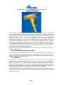
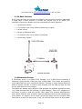
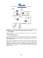
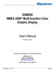
2.1 Network Characteristics
An NMEA 2000 network consists of a single network cable (the backbone) running
the length of a boat, with drop cables branching off the main backbone to connect to
individual devices (see diagram above). There can be up to 50 such connections to
devices, and there can be up to 252 logical addresses on the network, allowing for
multiple functions within one device (such as a combined speed, depth and water
temperature sensor). The speed of an NMEA 2000 network is 250K bits-per-second.
The network standard defines four levels of protocol: the physical layer, which
defines the cables and connectors; the datalink layer; the network layer; and the
application layer.
Some manufacturers have created their own proprietary physical layer that does not
conform to the standard, but all manufacturers use the same higher level protocols.
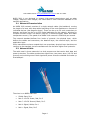
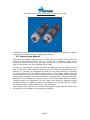
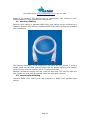
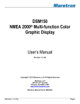
2.2 Network Cable
The cable used in these networks is a dual purpose one that carries both data and
power to devices. The cable contains two signal wires, two power wires (12V DC and
ground) and a shield ground. Both signal and power wires are shielded and make up
a twisted pair.
The wires in an NMEA cable are:
•
Shield: Bare, Pin 1
•
Net-S: 12V DC Power, Red, Pin 2
•
Net-C: 12V DC Ground, Black, Pin 3
•
Net-H: Signal, White, Pin 4
•
Net-L: Signal, Blue, Pin5
Page 4
Jack Rabbit Marine www.jackrabbitmarine.com 1-800-473-3981
Two standard sizes of network cable are defined. Heavy cable uses 16 AWG for
power and 18 AWG for signal wires, and Light cable uses 22 AWG for power and 24
AWG for signal wires. The maximum allowable backbone length for light cable is 100
meters. Recreational boats will almost all use this light cable, and the rest of this
document discusses only light cable. Cable is available in bulk, with user-installable
connectors, or in pre-made cordsets with connectors at either end.
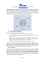
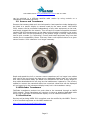
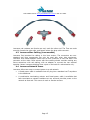
2.3 Components of a Network
There are five distinct elements in a network:
•
The backbone cable runs from one end of the boat to the other.
•
At intervals along the backbone, drop cables are attached. These run up to
network devices.
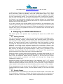
•
Where the drop cable meets the backbone, a T connector is used. This has a
socket either side for the backbone, and a third socket for the drop cable.
•
A power connector provides 12V DC power to the network.
•
At each end of the backbone, a terminating resistor must be fitted.
Devices on the network may be sensors, transducers, displays, or gateways to other
networks or to PCs – or anything else that either receives or transmits NMEA 2000
data. Some devices will have drop cables permanently attached. Others will have an
NMEA 2000 port on the back and the installer has to provide the cable. The same
type of cable is used for both the backbone and the drop cables.
2.4 Connectors
The connectors used on NMEA 2000 networks are defined by the network standard
physical layer. However, some manufacturers use their own proprietary wiring that
does not conform to the standard (e.g. Raymarine with SeaTalk NG, Lowrance with
LowranceNet Blue). Mixed networks can be created with standard and non-standard
wiring, provided adapter cables are used to bridge the two types of cabling. Maretron
cabling and Lowrance Red cabling uses standard connectors. All connectors contain
O-rings and are designed to be watertight.
Page 5
Jack Rabbit Marine www.jackrabbitmarine.com 1-800-473-3981
Connectors are either male or female, and when planning a network the gender
sequence of the cabling must be mapped out carefully.
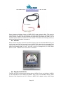
2.5 Powering the Network
Devices on the network may take up to 1 amp from the network cable, and so for
many low-power devices there will be no need for a separate power supply
connection, simplifying wiring on the boat. Devices with a power consumption too
high for the network will have separate power feeds.
If a device is powered by a source other than the network then the internal circuitry
that is powered by that external connection must be electrically separated from the
network. For example, a chartplotter will have its own power cable as it consumes
too much power to be run off the network power. This external power cable will
provide power to all of the internal components of the chartplotter except the NMEA
2000 network interface. The network interface is powered only by the network itself.
Data has to flow between the internal circuits of the chartplotter and the network
interface within the chartplotter, but this data flows across an optically-isolated
bridge that does not create any electrical connection. The point of this is to isolate
the network from any electrical failure in the chartplotter.
The network must have its own switched, fused power supply and this power must
be turned on for any data to flow through the network.
Page 6
Jack Rabbit Marine www.jackrabbitmarine.com 1-800-473-3981
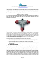
Power is fed to the network by a number of methods. Maretron uses a specialized
drop cable connected to the battery bank with a T connector on one end. This Power
T is inserted in the middle of the backbone and supplies power to the backbone cable
either side. The Power T can also be connected at one end of the backbone.
Lowrance makes a Power T and also a combined termination resistor and power
supply which attaches to one end of the backbone and both terminates that end of
the network and supplies power to it. Some Lowrance displays have a standard
power cable and a separate NMEA 2000 power cable. The NMEA 2000 power cable is
connected to the network and powers it using power from the same source (breaker)
as the display. This eliminates the need to run a separate feed from a 12V breaker to
the network and so simplifies installation.
NMEA 2000 devices are required to function correctly when supplied with DC power
between 9V and 16V.
2.6 Load Equivalency Number (LEN)
All NMEA 2000 devices should show an LEN on their nameplate. The LEN informs the
user of the current used by the device from the network. One LEN is equivalent to
50mA (0.05 amp). The sum of the LENs of the attached devices will determine the
power consumption of the network.
2.7 Gateways
Since there is a large installed base of instruments using other standards,
manufacturers will offer gateway devices that convert from one network standard to
another. For example, if a GPS antenna is already installed and outputs its data in
NMEA 0183 format, and the boat owner is installing an NMEA 2000 network, then a
gateway would be needed to convert the GPS NMEA 0183 messages to NMEA 2000
so that these messages can be received by any device on the network.
There will probably be an extended period in which manufactures also offer multiple
network connectors on devices, to make them compatible with whatever network is
installed on a boat.
Page 7
Jack Rabbit Marine www.jackrabbitmarine.com 1-800-473-3981
Another type of gateway will be one that connects an NMEA 2000 network to a PC
using an input such as the USB connector, to feed network data to applications
running on the PC.
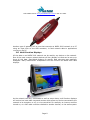
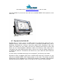
2.8 Multi-Function Displays
All the data on an NMEA 2000 network can be read by any device on the network.
One of the most common network devices will be a display unit that can be set up to
show all this data. Specialized displays for specific data elements may gradually
disappear. Many multifunction chartplotters will also function as NMEA 2000 data
displays.
As the network can carry commands as well as sensor data, multi-function displays
will evolve into boat-wide command centers which allow any device connected to the
network to be turned on or off, or to be controlled. For example, an inverter could be
turned on, or a VHF radio could be switched to another channel, or the audio system
Page 8
Jack Rabbit Marine www.jackrabbitmarine.com 1-800-473-3981
can be switched to a different satellite radio station by using controls on a
chartplotter mounted at the helm.
2.9 Sensors and Transducers
Sensors that measure data such as wind speed or boat speed are today designed to
be linked to a specific display or network made by the same vendor. With NMEA
2000, sensors can be purchased independently of any other equipment on the boat,
and simply plugged into the network. This will tend to increase competition between
vendors and focus development on the data and functionality provided by the sensor
itself, rather than on the compatibility of the product range. Currently, boat owners
tend to pick a vendor (i.e. Raymarine, Furuno) and install equipment only from that
vendor due to compatibility issues. That may mean a sub-optimal choice for a given
sensor function. Such a decision is no longer necessary.
Depth and speed thru-hull or transom-mount transducers will no longer have cables
that need to be run through the boat up to a dedicated display head, as is the case
with most instruments today. An NMEA 2000 transducer will have a short length of
drop cable attached and this will plug into the backbone as it passes by. The circuitry
needed to convert the transducer data into numerical values that can be displayed
will no longer be in the instrument display head, but in the transducer casing.
2.10 Fishfinder Transducers
Fishfinder transducers produce too much data to be connected through an NMEA
2000 network. These transducers will continue to have an attached dedicated cable
which runs to the back of the fishfinder display or to an external sounder unit.
2.11 Certification
Devices sold as being NMEA 2000 compliant must be certified by the NMEA. There is
a list of certified equipment on the NMEA website at:
http://www.nmea.org/pub/2000/index.html
Page 9
Jack Rabbit Marine www.jackrabbitmarine.com 1-800-473-3981
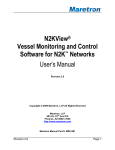
2.12 A Basic Network
Even if there are only two devices on a network, the connection cannot be made with
a single cable. A basic network to connect two devices such as an NMEA 2000
compliant engine and a display could be constructed with these elements.
•
A terminating resistor
•
A T connector with a drop cable to the device or engine
•
A power source
•
A length of backbone cable
•
A T connector with a drop cable to the display
•
A terminating resistor
2.13 Parameter Groups
A ‘parameter group’ is an NMEA 2000 message. It is a data record containing a
Parameter Group Number (PGN) and a set of data fields. The number and meaning
of the data fields vary from one PGN to another. Typically, a sensor device sends out
PGNs at regular intervals, or when a value changes, and this PGN can then be read
by any other device on the network.
The NMEA has defined many different PGNs grouped into different application areas
(e.g. PGNs that deal with fuel readings, or wind readings). There is no obligation for
any device to send or read any specific PGNs, apart from common administrative
ones. Which PGNs are sent or read by a device depends entirely on the manufacturer
of the device. For sensors, this is simple: a fuel tank sensor will only transmit PGNs
that have to do with fuel tank levels. It will not transmit PGNs to do with boat speed,
Page 10
Jack Rabbit Marine www.jackrabbitmarine.com 1-800-473-3981
or GPS position. Displays may choose to limit which PGNs they read – a Furuno FI-50
wind instrument reads and displays wind and speed-related PGNs only. When
choosing a multi-function display, it is necessary to examine carefully which PGNs
the unit is designed to handle. If you have an engine with an NMEA 2000 interface,
and you want to be able to see the engine instruments on a multi-function display on
the network, you must choose a display whose software designer has implemented
those engine-related PGNs and created a data screen for engine instruments. Some
displays may not offer this feature.
If you have a display with limited NMEA 2000 functionality, the manufacturer may
release a software upgrade which adds new features to the display and which causes
it to read PGNs that it previously ignored. All PGNs are available to all devices on the
network at all times, so upgrades of this sort are a software issue and usually don’t
call for new hardware.
3 Designing an NMEA 2000 Network
This section gives some practical tips on planning the layout of an NMEA 2000
network.
3.1 Getting Started
First list all the devices that you intend to connect to the network, including sensors,
transducers, displays, engines, radar antennas, GPS antennas, NMEA 0183 devices
and computers. Create a diagram of the boat’s layout and mark the location of these
devices. You need to choose a route for the backbone that is both practical (in terms
of pulling the cable) and which comes close to each of the connected devices. The
backbone must be a single continuous length with no branches. Draw in the
backbone on the diagram and mark the terminators at either end. Consider other
devices that you might add in the future and allow for these in the backbone routing.
Now mark on the diagram the proposed location of each of the T connectors in the
backbone, allowing enough Tees for drop cables to all devices. Think about future
growth and where Tees might need to go to accommodate this.
Choose a location to insert power into the backbone. The power cable should run to a
DC breaker, so a good place for the powertap might be behind the nav station or
helm where the backbone passes through. However, to be sure that your chosen
power insertion point is practical, you should work through the voltage drop
calculations in Section 3.6.
Estimate the length of each individual section of the backbone, from T to T, and the
length of each drop cable up to an attached device. Some devices may have drop
cables permanently attached, some have just a port on the back. List the lengths of
cable needed for the backbone and for drop cables, and the number of Tees needed.
If you have devices on the network that are NMEA 2000 compatible but do not have
standard NMEA drop cables or ports, note the adapter cables you will need for these
devices.
3.2 Gender Issues
T connectors have a male socket on one side and a female socket on the other side
for the backbone connections. Cordsets also have a male socket on one end and a
female on the other. This makes for a simple MFMFM sequence along the backbone.
Page 11
Jack Rabbit Marine www.jackrabbitmarine.com 1-800-473-3981
The PowerTap T from Maretron is not like other Tees. It has a female socket either
side, as Maretron took the design decision that exposed pins should not be
energized. This means that if you are using the Maretron power connector, you must
plan the gender sequence from the power supply out to either end of the network.
One side will be the mirror image of the other.
…MFMFM – F Power F – MFMFM…
If you are using LowranceNet Red cabling, the power cable connects to a standard T
with male one side and female the other, so the gender sequence along the
backbone is not affected.
The side of the T to which the drop cable will attach is always female i.e. drop cables
should have male sockets on the end that attaches to the T on the backbone.
Devices that do not have drop cables permanently attached should have a male port
on the back of the device. The female end of a cordset plugs into the back of the
device, and the male end of the cordset plugs into the T on the backbone.
3.3 Constraints on the Design
Any NMEA network must be designed to comply with these rules:
•
The total length of the backbone must not exceed 100 meters for light cable
•
Each drop cable must be no longer than 6 meters for light cable
•
There must be a terminating resistor at each end of the backbone (and
nowhere else)
3.4 Masthead Devices
The limitation on the length of a drop cable can create problems for devices at the
top of sailboat masts or on tower structures on power boats. Typically, the backbone
will run through the boat low down in the hull, and the distance up to the top of the
mast or tower can easily exceed 6 meters. The solution is to arrange the network so
that it is a continuation of the backbone that runs up the mast or tower, not a drop
cable. On a sailboat, for example, with an ultrasonic weatherstation at the masthead,
the backbone will run from stern to bow and then circle back to the base of the mast
and run up inside the mast. The backbone can be 100 meters long, making this
routing feasible on anything smaller than a superyacht. Usually a backbone would
end in a T with a drop cable to a device and a terminating resistor on the other side
Page 12
Jack Rabbit Marine www.jackrabbitmarine.com 1-800-473-3981
of the T. This arrangement may be too clumsy for the limited space in a sailboat
masthead. Maretron makes a special inline terminator which is used between the end
of the backbone and the weatherstation or other device, and this terminates the
network correctly while giving a more compact installation.
3.5 Extending the Network
Any NMEA 2000 network can be easily extended by just adding extra backbone cable
to one end of the network. Do not try to create a branch off the backbone to extend
the network – this won’t work. The backbone must be one continuous length with a
terminating resistor at each end.
The network can also be extended by adding in another T connector at some point
along the backbone, and attaching a new drop cable at that point. If an existing
backbone cable has to be cut, user-attachable connectors are available to go on the
ends of the cable.
3.6 Calculating Backbone Voltage Drop
Before deciding on the location of the power insertion point in an NMEA 2000
network, you should make an estimate of the power usage of the attached devices
and the consequent voltage drop along the network to be sure that your design will
not cause any power-related problems. A general screening formula which gives a
conservative result is:
Voltage Drop = 0.1 * Network Loads * Backbone Length * (Cable Resistance/100)
where
Network Loads = sum of the LENs of all attached devices
Backbone Length = total backbone length in meters
Cable Resistance = 5.74 ohms per 100 meters for light cable
Example
A network has attached to it an engine interface (2 LEN), a multi-function display (7
LEN), an electronic compass (1 LEN), a speed/depth transducer (2 LEN) and an
autopilot (1 LEN) for a total of 13 LEN. The total length of the backbone is 14.3
meters. The length of the drop cables is not counted in this calculation.
Voltage Drop = 0.1 * 13 * 14.3 * (5.74/100) = 1.1V
If the calculated voltage drop using this screening formula is less than 1.5V, then it
does not matter where along the backbone the power is inserted. If the calculated
voltage drop is between 1.5V and 3.0V, the power connection should be near the
mid-point of the backbone. If the calculated voltage drop exceeds 3.0V, then you
need to get a trained NMEA 2000 technician to look at your network design and
perform a more detailed calculation. In such a case, you may need to use heavy
cable for the backbone (heavy cable has a lower resistance of 1.61 ohms per 100
meters).
4 Manufacturer Variations
Some manufacturers adhere to the higher-level NMEA 2000 protocols but have
chosen to use a different physical layer. Others have specific ways of connecting
Page 13
Jack Rabbit Marine www.jackrabbitmarine.com 1-800-473-3981
power to the network. This section lists, by manufacturer, any unusual or nonstandard aspects of that manufacturer’s equipment.
4.1 Maretron Cabling
Maretron Micro cabling is standard NMEA 2000 light cabling and all connectors are
standard. Maretron Mini cabling is standard NMEA 2000 heavy cabling with standard
heavy connectors.
The Maretron PowerTap T is not configured in the same way as a normal T. It has a
female socket on both sides, and this means that the gender sequence of a network
using this form of power insertion has to be carefully planned.
Maretron cordsets are female one end, male the other end. The Tees are male one
side, female the other side, and female where the drop cable connects.
4.2 Lowrance Red Cabling
Lowrance NMEA 2000 cabling with red connectors is NMEA 2000 standard light
cabling.
Page 14
Jack Rabbit Marine www.jackrabbitmarine.com 1-800-473-3981
Lowrance red cordsets are female one end, male the other end. The Tees are male
one side, female the other side, and female where the drop cable connects.
4.3 Lowrance Blue Cabling (LowranceNet)
Lowrance first launched its cabling in this blue version. The connectors are nonstandard and blue components can only be used with other blue equipment.
Lowrance now makes adapter cables with a blue connector at one end and a red
connector at the other. Boat owners with blue cabling should consider making any
future extensions with red cabling, with an adapter to connect the two sections
together. Newer Lowrance displays have a port on the back for red networks only.
4.4 Lowrance Network Power
Lowrance offers two ways to connect power to a red network:
•
A fused power cable is available that will plug into a standard red T anywhere
in the backbone.
•
A combination terminating resistor and fused power cable is available that
both terminates a network backbone at one end and provides power to the
network at that end. This comes in male or female versions.
Page 15
Jack Rabbit Marine www.jackrabbitmarine.com 1-800-473-3981
Some Lowrance displays have an NMEA 2000 power output cable. This can be
connected to the network using one of the two methods above. Using this power
source, which is fed by the same breaker as the display, eliminates the need to run a
separate power cable to a breaker for the network. The network will always power up
when the display’s breaker is turned on.
4.5 Garmin
Newer Garmin displays (the 4000 and 5000 Series) have a standard NMEA 2000 port
on the back and can be connected to any NMEA 2000 network using standard light
cabling. Garmin has chosen to limit the types of information used by the displays to
engine and heading data in 2007, but this is likely to change early in 2008 when
Garmin’s GMI 10 NMEA 2000 instrument is available.
4.6 Raymarine E-Series
The E80 and E120 multifunction displays have a SeaTalk 2 port on the back. SeaTalk
2 was Raymarine’s first attempt at NMEA 2000, with non-standard cabling. Both
Maretron and Raymarine sell an E-Series to NMEA 2000 adapter cable, which plugs
Page 16
Jack Rabbit Marine www.jackrabbitmarine.com 1-800-473-3981
into the SeaTalk 2 port at one end, and into a standard NMEA 2000 network on the
other end.
4.7 Raymarine SeaTalk NG
SeaTalk NG is a newer version of NMEA 2000 from Raymarine, again with nonstandard cabling. The structure of the network is identical to NMEA 2000, with a
backbone terminated by resistors, and drop cables which Raymarine calls spur
cables. The cables are color-coded, with blue for backbone and white for spurs and
these are not interchangeable. Backbone cables are female at both ends, and T
connectors have male sockets either side so there is no need for gender planning in
a SeaTalk NG network. Terminators are female only. Spur cables are also female at
both ends.
A power cable is available that plugs into a standard T just like any spur cable.
Raymarine offers an adapter cable with a SeaTalk NG white spur connector on one
end and a standard NMEA 2000 female socket on the other. This allows an NMEA
2000 device to be plugged into a SeaTalk NG network. An adapter cable between
SeaTalk NG and the SeaTalk 2 port on the back of the E-Series is also available.
Page 17
Jack Rabbit Marine www.jackrabbitmarine.com 1-800-473-3981
Transducer pods are offered that connect to conventional depth, speed or wind
transducers on one side, and a SeaTalk NG network on the other side. These allow
boat owners to convert to NG without needing to replace the transducers.
4.8 Northstar
Northstar equipment uses the SmartCraft network standard, and no NMEA 2000
interface is available.
4.9 Furuno NavNet 3D
Furuno launched NavNet 3D in October 2007 and full details are not yet available.
The 3D displays have a NMEA 2000 connector on the back and can be used with any
standard NMEA 2000 network. Furuno provides a long list of PGNs that are input and
output by the displays.
Furuno also offers a ‘network-in-a box’ device. This is an enclosure with a port at
either end for a terminator, and six ports for drop cables. It is a complete NMEA
2000 backbone structure in one piece of equipment, for networks where all the
components are within easy reach of each other, though the network can be
extended from either side of the box. Connections to this device are not with
standard NMEA 2000 connectors – it uses a form of terminal block that accepts
stripped wires only.
Page 18
Jack Rabbit Marine www.jackrabbitmarine.com 1-800-473-3981
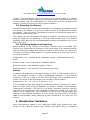
4.10 Furuno FI-50 Instruments
As part of the NavNet 3D launch, Furuno has also announced a range of NMEA 2000
instruments. These are the FI-501 analog wind display; FI-502 analog close-hauled
wind display; FI-503 digital display of depth, speed, water temperature and log; FI504 digital multi repeater; FI-505 course pilot and FI-506 rudder angle indicator.
All the instruments have two NMEA 2000 ports on the back so that a drop cable can
in effect be run as a daisy-chain through a string of the instruments. The depth and
speed transducer used is the Airmar DST800 NMEA 2000 unit. The wind transducer is
a conventional one with a cable that must run directly to the wind display. The FI-50
Series instruments can be used on any NMEA 2000 network and are not limited to
use with NavNet 3D equipment.
Page 19
Jack Rabbit Marine www.jackrabbitmarine.com 1-800-473-3981
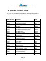
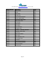
5 NMEA 2000 Parameter Groups
This list has been assembled from manufacturer’s manuals and other sources. It is
not guaranteed accurate or complete. This list has not been approved by the NMEA,
and is not derived from their publications.
NMEA 2000 PGN
Description
Type
126464
PGN List
Admin
126996
Product Information
Admin
126998
Configuration Information
Admin
059392
ISO Acknowledge
Network
059904
ISO Request
Network
060416
ISO Transport Protocol, Connection Mgmt
Network
060160
ISO Transport Protocol, Data Transfer
Network
060928
ISO Address Claim
Network
065240
ISO Address Command
Network
126206
NMEA Complex Request/Command/Ack
Network
126208
Command Group
Command
126992
System Time
Data
127237
Heading/Track Control
Data
127245
Rudder
Data
127250
Vessel Heading
Data
127251
Rate of Turn
Data
127257
Attitude
Data
127258
Magnetic Variation
Data
127488
Engine Parameters, Rapid Update
Data
127489
Engine Parameters, Dynamic
Data
127493
Transmission Parameters, Dynamic
Data
127497
Trip Parameters, Engine
Data
127498
Engine Parameters, Static
Data
127505
Fluid Level
Data
Page 20
Jack Rabbit Marine www.jackrabbitmarine.com 1-800-473-3981
NMEA 2000 PGN
Description
Type
127508
Battery Status
Data
128259
Speed
Data
128267
Water Depth
Data
128275
Distance Log
Data
128311
Environmental Parameters
Data
129025
Position, Rapid Update
Data
129026
COG & SOG, Rapid Update
Data
129029
GNSS Position Data
Data
129033
Time & Date
Data
129044
Chart Datum
Data
129045
User Datum
Data
129283
Cross Track Error
Data
129284
Navigation Data
Data
129285
Navigation – Route/WP Information
Data
129291
Set & Drift, Rapid Update
Data
129301
Time To Go
Data
129538
GNSS Control Status
Data
129539
GNSS DOPs
Data
129540
GNSS Satellites in View
Data
129541
GPS Almanac Data
Data
130306
Wind Data
Data
130310
Environmental Parameters
Data
130311
Environmental Parameters
Data
130576
Small Craft Status
Data
130577
Direction Data
Data
Page 21
Jack Rabbit Marine www.jackrabbitmarine.com 1-800-473-3981
6 Sample PGN Detailed Definitions
These detailed definitions list the fields contained in each Parameter Group and the
meaning of each field. These definitions are taken from Maretron manuals and may
contain references to specific devices. Some field values given are specific to a
device and may take different values in other manufacturer’s devices. These
definitions are samples for guidance only.
6.1 PGN 126208 – NMEA Command Group Function – Distance
Log Reset
This command will reset the “Distance Since Last Reset” field of the Distance Log
PGN (128275).
Field 1: Complex Command Group Function Code (8 bits) – set this field’s value to
0x01, which denotes a command PGN
2: Commanded PGN (24 bits) – set this field’s value to 128275, which denotes the
Distance Log PGN
3: Priority Setting (4 bits) – set this field’s value to 0x8, which indicates to leave
priority settings unchanged
4: Reserved (4 bits) – set this field’s value to 0xF, which is the value for a reserved
field of this size
5: Number of Pairs of Commanded Parameters to Follow (8 bits) – set this field’s
value to 0x1, indicating that one parameter will follow
6: Number of First Commanded Parameter (8 bits) – set this field’s value to 0x4,
which indicates the Distance Since Last Reset field
7: Distance Since Last Reset (16 bits) – set this field’s value 0 to reset the Distance
Since Last Reset counter to zero.
6.2 PGN 126208 – NMEA Command Group Function – Offset
Calibration
Field 1: Complex Command Group Function Code (8 bits) – set this field’s value to
0x01, which denotes a command PGN
2: Commanded PGN (24 bits) – set this field’s value to 128267, which denotes the
Water Depth PGN 3: Priority Setting (4 bits) – set this field’s value to 0x8, which
indicates to leave priority settings unchanged
4: Reserved (4 bits) – set this field’s value to 0xF, which is the value for a reserved
field of this size
5: Number of Pairs of Commanded Parameters to Follow (8 bits) – set this field’s
value to 0x1, indicating that one parameter will follow
Page 22
Jack Rabbit Marine www.jackrabbitmarine.com 1-800-473-3981
6: Number of First Commanded Parameter (8 bits) – set this field’s value to 0x3,
which indicates the Offset field
7: Offset (16 bits) – set this field’s value to the desired offset value. Units of
measurement for this field are 1x10⁻³m. Positive values indicate the depth of the
transducer below the waterline. For instance, if the transducer is located 2.5 m below
the waterline, set this field’s value to 2500 (0x09C4). If the bottom of the keel is
located 2.5 m below the transducer, set this field’s value to -2500 (0xF63C).
6.3 PGN 126992 – System Time
Field 1: SID – The sequence identifier field is used to tie related PGNs together. For
example, the GPS100 will transmit identical SIDs for 126992 (System Time), 128259
(Speed), 129026 (COG and SOG, Rapid Update), 129029 (GNSS Position Data),
129539 (GNSS DOPs), and 129540 (GNSS Satellites in View) to indicate that the
readings are linked together (i.e., the data from each PGN was taken at the same
time although they are reported at slightly different times).
2: Source – This field is used to indicate the type of time source, therefore this field
always reads as 0 (GPS).
3: Reserved (4 bits) – This field is reserved by NMEA
4: Date – This field is used to indicate the UTC Date in resolution of 1 day (the
number of days since January 1, 1970).
5: Time – This field is used to indicate the UTC Time in resolution of 1x10⁻⁴ s (24
hour clock, 0.0000 = midnight).
6.4 PGN 127245 – Rudder
Field 1: Rudder Instance – This field is used to identify the rudder instance number
and ranges between 0 and 251.
2: Direction Order – This field identifies a directional command contained in this
message. The RAA100 ships from the factory with a default value of 0x0 indicating
that no direction order is contained in this message.
3: Reserved – This field is reserved by NMEA
4: Angle Order – This field is used to indicate an angle order directed towards a
rudder actuator The RAA100 ships from the factory with a default value of 0x7FFF
indicating that no angle order is present in this message.
5: Position – This field is used to indicate the current angle of the rudder in units of
0.0001 radians.
6: Reserved – This field is reserved by NMEA
6.5 PGN 127250 – Vessel Heading
Field 1: SID – The sequence identifier field is used to tie related PGNs together. For
example, the SSC200 will transmit identical SIDs for Vessel Heading (PGN 127250),
Attitude (127257), and Rate of Turn (127251) to indicate that the readings are
Page 23
Jack Rabbit Marine www.jackrabbitmarine.com 1-800-473-3981
linked together (i.e., the data from each PGN was taken at the same time although
they are reported at slightly different times).
2: Heading Sensor Reading – This field is used to report the vessel’s heading and
includes deviation assuming a deviation table has been successfully loaded through
the magnetic deviation calibration process.
3: Deviation – The deviation is included in field 2, therefore this field always reads as
0.
4: Variation – The SSC200 does not use this field so the field is transmitted with the
value 0x7FFF (data not available). See PGN 127258 for information regarding the
SSC200 and its ability to transmit magnetic variation.
5: Heading Sensor Reference – The SSC200 transmits a “1” in this field to indicate
that the heading is referenced to magnetic North
6: Reserved – This field is reserved by NMEA
6.6 PGN 127251 – Rate of Turn
Field 1: SID – The sequence identifier field is used to tie related PGNs together. For
example, the SSC200 will transmit identical SIDs for Vessel Heading (PGN 127250),
Attitude (127257), and Rate of Turn (127251) to indicate that the readings are
linked together (i.e., the data from each PGN was taken at the same time although
they are reported at slightly different times).
2: Rate of Turn – This field is used to report the vessel’s rate of turn.
3: Reserved – This field is reserved by NMEA
6.7 PGN 127257 – Attitude
The SSC200 uses this PGN to indicate the vessel’s attitude (pitch and roll). The Yaw
(field 2) is not used, therefore this field always contains 0x7FFF (data not available).
Field 1: SID – The sequence identifier field is used to tie related PGNs together. For
example, the SSC200 will transmit identical SIDs for Vessel Heading (PGN 127250),
Attitude (127257), and Rate of Turn (127251) to indicate that the readings are
linked together (i.e., the data from each PGN was taken at the same time although
they are reported at slightly different times).
2: Yaw – This field always contains a value of 0x7FFF (data not available).
3: Pitch – This field is used to report the vessel’s pitch.
4: Roll – This field is used to report the vessel’s roll.
5: Reserved – This field is reserved by NMEA
6.8 PGN 127258 – Magnetic Variation
Field 1: SID – The sequence identifier field is used to tie related PGNs together. For
example, the GPS100 will transmit identical SIDs for 126992 (System Time), 128259
Page 24
Jack Rabbit Marine www.jackrabbitmarine.com 1-800-473-3981
(Speed), 129026 (COG and SOG, Rapid Update), 129029 (GNSS Position Data),
129539 (GNSS DOPs), and 129540 (GNSS Satellites in View) to indicate that the
readings are linked together (i.e., the data from each PGN was taken at the same
time although they are reported at slightly different times).
2: Variation Source – The GPS100 uses the WMM2005 for variation, therefore this
field always reads as 5 (WMM2005).
3: Reserved (4 bits) – This field is reserved by NMEA
4: Age of Service (Date) – This field is used to indicate the UTC Date in resolution of
1 day (the number of days since January 1, 1970).
5: Variation – This field is used to indicate the magnetic variation where positive
values represent Easterly and negative values represent Westerly variation.
6.9 PGN 127488 – Engine Parameters, Rapid Update
Field 1: Engine Instance – This field indicates the particular engine for which this
data applies. A single engine will have an instance of 0. Engines in multi-engine
boats will be numbered starting at 0 at the bow of the boat incrementing to n going
in towards the stern of the boat. For engines at the same distance from the bow are
stern, the engines are numbered starting from the port side and proceeding towards
the starboard side.
2: Engine Speed – This field indicates the rotational speed of the engine in units of ¼
RPM.
3: Engine Boost Pressure – This field indicates the turbocharger boost pressure in
units of 100 Pa.
4: Engine tilt/trim – This field indicates the tilt or trim (positive or negative) of the
engine in units of 1 percent.
5: Reserved – This field is reserved by NMEA
6.10 PGN 127489 – Engine Parameters, Dynamic
Field 1: Engine Instance – This field indicates the particular engine for which this
data applies. A single engine will have an instance of 0. Engines in multi-engine
boats will be numbered starting at 0 at the bow of the boat incrementing to n going
in towards the stern of the boat. For engines at the same distance from the bow are
stern, the engines are numbered starting from the port side and proceeding towards
the starboard side.
2: Engine Oil Pressure – This field indicates the oil pressure of the engine in units of
100 Pa.
3: Engine Oil Temperature – This field indicates the oil temperature of the engine in
units of 0.1°K.
4: Engine Temperature – This field indicates the temperature of the engine coolant in
units of 0.1°K.
5: Alternator Potential – This field indicates the alternator voltage in units of 0.01V.
Page 25
Jack Rabbit Marine www.jackrabbitmarine.com 1-800-473-3981
6: Fuel Rate – This field indicates the fuel consumption rate of the engine in units of
0.0001 cubic meters / hour.
7: Total Engine Hours – This field indicates the cumulative runtime of the engine in
units of 1 second.
8: Engine Coolant Pressure – This field indicates the pressure of the engine coolant
in units of 100 Pa.
9: Fuel Pressure – This field indicates the pressure of the engine fuel in units of 1000
Pa.
10: Reserved – This field is reserved by NMEA
11: Engine Discrete Status 1 – This field indicates warning conditions of the engine
with the following bit assignments (value of 1 indicates warning present):
Bit 0: Check Engine
Bit 1: Over Temperature
Bit 2: Low Oil Pressure
Bit 3: Low Oil Level
Bit 4: Low Fuel Pressure
Bit 5: Low System Voltage
Bit 6: Low Coolant Level
Bit 7: Water Flow
Bit 8: Water in Fuel
Bit 9: Charge Indicator
Bit 10: Preheat Indicator
Bit 11: High Boost Pressure
Bit 12: Rev Limit Exceeded
Bit 13: EGR System
Bit 14: Throttle Position Sensor
Bit 15: Emergency Stop Mode
12: Engine Discrete Status 2 – This field indicates warning conditions of the engine
with the following bit assignments (value of 1 indicates warning present):
Bit 0: Warning Level 1
Bit 1: Warning Level 2
Bit 2: Power Reduction
Bit 3: Maintenance Needed
Bit 4: Engine Comm Error
Bit 5: Sub or Secondary Throttle
Page 26
Jack Rabbit Marine www.jackrabbitmarine.com 1-800-473-3981
Bit 6: Neutral Start Protect
Bit 7: Engine Shutting Down
Bit 8-15: These bits are reserved and should be masked when read
13: Percent Engine Load – This field indicates the percent load of the engine in units
of 1 percent.
14: Percent Engine Torque – This field indicates the percent torque of the engine in
units of 1 percent.
6.11 PGN 127493 – Transmission Parameters, Dynamic
Field 1: Transmission Instance – This field indicates the particular transmission for
which this data applies. A single transmission will have an instance of 0.
Transmissions in multi-transmission boats will be numbered starting at 0 at the bow
of the boat incrementing to n going in towards the stern of the boat. For
transmissions at the same distance from the bow are stern, the transmissions are
numbered starting from the port side and proceeding towards the starboard side.
2: Transmission Gear – This field indicates the current gear the transmission is
operating in.
3: Reserved – This field is reserved by NMEA
4: Transmission Oil Pressure – This field indicates the oil pressure of the
transmission in units of 100 Pa.
5: Transmission Oil Temperature – This field indicates the oil temperature of the
transmission in units of 0.1°K.
6: Transmission Discrete Status – This field indicates warning conditions of the
transmission with the following bit assignments (value of 1 indicates warning
present):
Bit 0: Check Transmission
Bit 1: Over Temperature
Bit 2: Low Oil Pressure
Bit 3: Low Oil Level
Bit 4: Sail Drive
Bit 5-8: These bits are reserved and should be masked when read
7: Reserved – This field is reserved by NMEA
6.12 PGN 127498 – Engine Parameters, Static
Field 1: Engine Instance – This field indicates the particular engine for which this
data applies. A single engine will have an instance of 0. Engines in multi-engine
boats will be numbered starting at 0 at the bow of the boat incrementing to n going
in towards the stern of the boat. For engines at the same distance from the bow are
Page 27
Jack Rabbit Marine www.jackrabbitmarine.com 1-800-473-3981
stern, the engines are numbered starting from the port side and proceeding towards
the starboard side.
2: Rated Engine Speed – This field indicates the maximum rated rotational speed of
the engine in units of ¼ RPM.
3: VIN – This field indicates the Vehicle Identification Number of the engine as a
textual representation.
4: Software ID – This field indicates the version number or other identifying
information for the software in the engine as a textual representation.
6.13 PGN 127505 – Fluid Level
Field 1: Fluid Instance – This field is used to identify the tank number and ranges
between 0 and 15. There can be up to 16 tanks of a given type as defined by the
Fluid Type field. This field is programmable through the NMEA command PGN. The
TLA100 ships from the factory with a default value of zero.
2: Fluid Type – This field identifies the type of fluid contained within the tank.
Currently the defined fluid types are fuel, fresh water, wastewater, live well, oil, and
black water. The TLA100 ships from the factory with a default value of 0x0 indicating
“Fuel”.
3: Fluid Level – This field is used to indicate the current fluid level in percentage. The
value transmitted in this field depends on the sender resistance value..
4: Tank Capacity – This field is used to indicate the tank capacity. The TLA100 ships
from the factory with a default value of 0xFFFFFFFF indicating “Data Not Available”.
5: Reserved – This field is reserved by NMEA
6.14 PGN 128259 – Speed
Field 1: SID – The sequence identifier field is used to tie related PGNs together. For
example, a compass would transmit identical SIDs for Water depth (128267) and
Speed (PGN 128259) to indicate that the readings are linked together (i.e., the data
from each PGN was taken at the same time although reported at slightly different
times).
2: Speed, Water Referenced – This field is used to report the vessel’s speed relative
to the water in units of 1x10⁻² meters per second.
3: Speed Ground Referenced – This field is used to indicate the speed over ground
(SOG) in resolution of 1x10⁻² m/s.
4: Reserved – This field is reserved by NMEA
6.15 PGN 128267 – Water Depth
The DST100 uses this PGN to indicate the water depth relative to the transducer and
offset of the measuring transducer.
Page 28
Jack Rabbit Marine www.jackrabbitmarine.com 1-800-473-3981
Field 1: SID – The sequence identifier field is used to tie related PGNs together. For
example, the DST100 will transmit identical SIDs for Speed (PGN 128259) and Water
depth (128267) to indicate that the readings are linked together (i.e., the data from
each PGN was taken at the same time although reported at slightly different times).
2: Water Depth, Transducer – This field is used to report the depth relative to the
transducer in units of 1x10⁻² m.
3: Offset – If the value of this field is positive, it represents the difference in depth
between the transducer and the waterline of the vessel. If the value of this field is
negative, it represents the difference in depth between the transducer and the keel
of the vessel. The unit of measurement for this field is 1x10⁻³ m.
4: Reserved – This field is reserved by NMEA
6.16 PGN 128275 – Distance Log
Field 1: Measurement Date – This field is not used by the DST100; therefore, it
transmits a value of 0xFFFF (65,535) for this field (which represents “data not
available”).
2: Measurement Time – This field is not used by the DST100; therefore, it transmits
a value of 0xFFFFFFFF (4,) for this field (which represents “data not available”).
3: Total Cumulative Distance – This field indicates the total distance traveled through
the water since the DST100 was installed in units of 1 m.
4: Distance Since Last Reset – This field indicates the total distance traveled through
the water since this parameter was last reset. This is most commonly reset at the
beginning of a voyage and then reflects the total distance traveled in that voyage.
The unit of measurement for this field is 1 m.
6.17 PGN 129025 – Position, Rapid Update
Field 1: Latitude – Latitude in 1x10⁻⁷ degrees ("-" = south, “+” = north)
2: Longitude – Longitude in 1x10⁻⁷ degrees ("-" = west, “+” = east)
6.18 PGN 129026 – COG and SOG, Rapid Update
Field 1: SID – The sequence identifier field is used to tie related PGNs together. For
example, the GPS100 will transmit identical SIDs for 126992 (System Time), 128259
(Speed), 129026 (COG and SOG, Rapid Update), 129029 (GNSS Position Data),
129539 (GNSS DOPs), and 129540 (GNSS Satellites in View) to indicate that the
readings are linked together (i.e., the data from each PGN was taken at the same
time although they are reported at slightly different times).
2: COG Reference – This field is used to indicate the direction reference of the course
over ground. This field always reads as 0 (True, not magnetic).
3: Reserved (6 bits) – This field is reserved by NMEA
Page 29
Jack Rabbit Marine www.jackrabbitmarine.com 1-800-473-3981
4: Course Over Ground – This field is used to indicate the course over ground (COG)
in resolution of 1x10⁻⁴ radians.
5: Speed Over Ground – This field is used to indicate the speed over ground (SOG)
in resolution of 1x10⁻² m/s.
6: Reserved (16 bits) – This field is reserved by NMEA
6.19 PGN 129029 – GNSS Position Data
Field 1: SID – The sequence identifier field is used to tie related PGNs together. For
example, the GPS100 will transmit identical SIDs for 126992 (System Time), 128259
(Speed), 129026 (COG and SOG, Rapid Update), 129029 (GNSS Position Data),
129539 (GNSS DOPs), and 129540 (GNSS Satellites in View) to indicate that the
readings are linked together (i.e., the data from each PGN was taken at the same
time although they are reported at slightly different times).
2: Position date –UTC Date in resolution of 1 day (The number of days since January
1, 1970).
3: Position time – UTC Time in resolution of 1x10⁻⁴ s (24 hour clock, 0.0000 =
midnight).
4: Latitude – Latitude in 1x10-16 degrees ("-" = south, “+” = north)
5: Longitude – Longitude in 1x10-16 degrees ("-" = west, “+” = east)
6: Altitude – Altitude referenced to WGS-84 in (resolution of 1x10⁻⁶ m)
7: Type of System – This field is used to indicate type of GPS system. The GPS100
will show either 0 (GPS) or 3 (GPS+SBAS, factory default) dependent on whether the
user has enabled SBAS.
8: Method, GNSS – This field is used to indicate the quality of GNSS information. The
GPS100 indicates one of the following values: 0=no GPS, 1=GNSS fix, 2=DGNSS fix,
6=Estimated (dead reckoning).
9: Integrity – This field always contains a value of 0 (no integrity checking).
10: Reserved (6 bits) – This field is reserved by NMEA
11: Number of SVs – This field is used to indicate the number of satellites used in
solution.
12: HDOP – This field is used to indicate the horizontal dilution of precision with a
resolution of 1x10⁻² (unitless).
13: PDOP – This field is used to indicate the positional dilution of precision with a
resolution of 1x10⁻² (unitless).
14: Geoidal Separation – This field is used to indicate the Geoidal Separation in
resolution of 1x10⁻² m.
15: Number of Reference Stations – This field always contains a value of 0
16: Reference Station Type "1" – This field always contains a value of 0xF (Null)
Page 30
Jack Rabbit Marine www.jackrabbitmarine.com 1-800-473-3981
17: Reference Station ID "1" – This field always contains a value of 0xFFF (data not
available)
18: Age of DGNSS Corrections "1" – This field always contains a value of 0xFFFF
(data not available)
6.20 PGN 129538 – GNSS Control Status
Field 1: SV Elevation Mask – If the elevation of a satellite (angle above the horizon)
is below this value, the GPS100 will not use that satellite in the solution. Units are
1x10⁻⁴ radians. The factory default for this value is 0.1309 radians , which
corresponds to 7.5°.
2: PDOP Mask – If the PDOP exceeds this value, the GPS100 will indicate “No GNSS
fix” or “Dead Reckoning Mode” in PGN 129029. Units are 1x10⁻² (unitless). The
factory default is to report a fix whenever possible, regardless of PDOP.
3: PDOP Switch – If the PDOP exceeds this value, a GPS receiver will switch from 3D
to 2D mode. For the GPS100, this field always contains a value of 0x7FFF, indicating
that the GPS100 will always attempt to operate in 3D mode. Units are 1x10⁻²
(unitless). The factory default is to report a fix whenever possible, regardless of
PDOP.
4: SNR Mask – If the SNR of a satellite is below this value, the GPS100 will not use
that satellite in the solution. Units are 1x10⁻² dB. The factory default is to use all
available satellites. The factory default setting for the SNR Mask is 28 dB.
5: GNSS Mode – This field is used to indicate the desired mode of operation: 0 = 1D,
1 = 2D, 2 = 3D, 3 = Auto (factory default), 4-5 = Reserved, 6 = Error, 7 = Null.
6: DGNSS Mode – This field is used to indicate the desired mode of operation of
DGNSS (0=do not use SBAS, 1 and 3=Use SBAS when available). The factory default
value for this field is 1 (use SBAS when available).
7: Position / Velocity Filter – This field always contains a value of 0x3, indicating that
the GPS100 does not allow configuration of the position / velocity filter.
8: Max Correction Age – This field always contains a value of 0xFFFF, indicating that
the GPS100 does not allow configuration of the maximum age of SBAS correction
data to be used.
9: Antenna Altitude for 2D Mode – This field is used to indicate the antenna altitude
for the GPS100 to use when operating in 2D mode in units of 1x10⁻² m. The factory
default for this field is 0.0 m.
10: Use Antenna Altitude for 2D Mode – This field is used to indicate whether the
GPS100 will use Antenna Altitude (Field 9) when operating in 2D mode. The factory
default for this field is 0 (do not use the antenna altitude; rather, use the altitude
calculated when the GPS100 was most recently in 3D mode).
Page 31
Jack Rabbit Marine www.jackrabbitmarine.com 1-800-473-3981
6.21 PGN 129539 – GNSS DOPs
Field 1: SID – The sequence identifier field is used to tie related PGNs together. For
example, the GPS100 will transmit identical SIDs for 126992 (System Time), 128259
(Speed), 129026 (COG and SOG, Rapid Update), 129029 (GNSS Position Data),
129539 (GNSS DOPs), and 129540 (GNSS Satellites in View) to indicate that the
readings are linked together (i.e., the data from each PGN was taken at the same
time although they are reported at slightly different times).
2: Set Mode – This field is used to indicate the desired mode of operation: 0 = 1D. 1
= 2D, 2 = 3D, 3 = Auto (factory default), 4-5 = Reserved, 6 = Error, 7 = Null.
3: Op Mode – This field is used to indicate the actual current mode of operation: 0 =
1D. 1 = 2D, 2 = 3D, 3 = Auto (factory default), 4-5 = Reserved, 6 = Error, 7 = Null.
4: Reserved (2 bits) – This field is reserved by NMEA
5: HDOP – This field is used to indicate the horizontal dilution of precision with a
resolution of 1x10⁻² (unitless).
6: VDOP – This field is used to indicate the vertical dilution of precision with a
resolution of 1x10⁻² (unitless).
7: TDOP – This field is used to indicate the time dilution of precision with a resolution
of 1x10⁻² (unitless).
6.22 PGN 129540 – GNSS Satellites in View
Field 1: SID – The sequence identifier field is used to tie related PGNs together. For
example, the GPS100 will transmit identical SIDs for 126992 (System Time), 128259
(Speed), 129026 (COG and SOG, Rapid Update), 129029 (GNSS Position Data),
129539 (GNSS DOPs), and 129540 (GNSS Satellites in View) to indicate that the
readings are linked together (i.e., the data from each PGN was taken at the same
time although they are reported at slightly different times).
2: Mode – This field always reads as 3 (Null), indicating that range residuals are used
to calculate position, and not calculated after the position.
3: Reserved (6 bits) – This field is reserved by NMEA
4: Number of SVs – This field is used to indicate the number of current satellites in
view. Fields 5-11 are repeated the number of times specified by this field’s value.
5: PRN "1" – This field is used to indicate the Satellite ID Number of the satellite (132=GPS, 33-64=SBAS, 65-96=GLONASS).
6: Elevation "1" – This field is used to indicate the Elevation of the satellite.
7: Azimuth "1" – This field is used to indicate the Azimuth of the satellite.
8: SNR "1" – This field is used to indicate the Signal to Noise Ratio (SNR) of the
satellite.
9: Range Residuals “1” – The GPS100 always sets this field to a value of 0x7FFFFFFF
Page 32
Jack Rabbit Marine www.jackrabbitmarine.com 1-800-473-3981
(data not available)
10: PRN Status "1" – This field is used to indicate the status of the first satellite in
the list. (0=Not Tracked, 1=Tracked but not used in solution, 2=Used in solution
without Differential corrections, 3=Differential Corrections available, 4=Tracked with
Differential Corrections, 5=used with Differential Corrections)
11: Reserved (4 bits) – This field is reserved by NMEA
If Field 4 contains a value greater than one, then the group of fields 5 through 11 is
repeated until this group appears the number of times indicated by the value of Field
4.
6.23 PGN 129541 – GPS Almanac Data
Field 1: PRN – PRN of the satellite for which almanac data is being provided.
2: GPS Week Number – The number of weeks since Jan 6, 1980.
3: SV Health Bits – Bits 17-24 of each almanac page. Refer to ICD-GPS-200
paragraph 20.3.3.5.1.3, Table 20-VII and Table 20-VIII.
4: Eccentricity – Reference ICD-GPS-200 Table 20-VI.
5: Almanac Reference Time – Reference ICD-GPS-200 Table 20-VI.
6: Inclination Angle – Reference ICD-GPS-200 Table 20-VI.
7: Rate of Right Ascension – The OMEGADOT parameter. Reference ICD-GPS-200
Table 20-VI.
8: Root of Semi-major Axis – Reference ICD-GPS-200 Table 20-VI.
9: Argument of Perigee – Reference ICD-GPS-200 Table 20-VI.
10: Longitude of Ascension Mode – Reference ICD-GPS-200 Table 20-VI.
11: Mean Anomaly – Reference ICD-GPS-200 Table 20-VI.
12: Clock Parameter 1 – Reference ICD-GPS-200 Table 20-VI.
13: Clock Parameter 2 – Reference ICD-GPS-200 Table 20-VI.
14: Reserved (2 bits) – This field is reserved by NMEA; therefore, this field always
contains a value of 0x3 (the GPS100 sets all bits to a logic 1)
6.24 PGN 130306 – Wind Data
Field 1: SID – The sequence identifier field is used to tie related PGNs together. For
example, the WSO100 will transmit identical SIDs for 130306 (Wind Data) and
130311 (Environmental Parameters) to indicate that the readings are linked together
(i.e., the data from each PGN was taken at the same time although they are reported
at slightly different times).
2: Wind Speed – This field is used to indicate the wind speed in units of
10mm/second.
Page 33
Jack Rabbit Marine www.jackrabbitmarine.com 1-800-473-3981
3: Wind Direction – This field is used to indicate the wind direction in units of 0.0001
radians/second.
4: Wind Reference – This field is set to a value of 0x02 to indicate that the wind
reading is an apparent wind speed and direction.
5: Reserved (21 bits) – This field is reserved by NMEA
6.25 PGN 130310 – Environmental Parameters
Field 1: SID – The sequence identifier field is used to tie related PGNs together.
Although the DST100 transmits a SID for the Environmental PGN, it is not tied to any
other PGNs.
2: Water Temperature – This field indicates the water temperature in units of 1x10²°K.
3: Outside Ambient Air Temp – This field is not used by the DST100; therefore, it
transmits a value of 0xFFFF (65,535) for this field (which represents “data not
available”).
4: Atmospheric Pressure – This field is not used by the DST100; therefore, it
transmits a value of 0xFFFF (65,535) for this field (which represents “data not
available”).
5: Reserved – This field is reserved by NMEA
6.26 PGN 130311 – Environmental Parameters
Field 1: SID – The sequence identifier field is used to tie related PGNs together. For
example, the WSO100 will transmit identical SIDs for 130306 (Wind Data) and
130311 (Environmental Parameters) to indicate that the readings are linked together
(i.e., the data from each PGN was taken at the same time although they are reported
at slightly different times).
2: Temperature Instance – The WSO100 sets this field to a value of 0x01 to indicate
that the temperature reading is a reading of outside temperature.
3: Humidity Instance – The WSO100 sets this field to a value of 0x01 to indicate that
the relative humidity reading is a reading of outside humidity.
4: Temperature – This field is used to indicate the outside air temperature in units of
0.01°K.
5: Humidity – This field is used to indicate the relative humidity in units of 0.004%.
6: Atmospheric Pressure – This field is used to indicate the barometric pressure in
units of 100 Pa.
Page 34