1
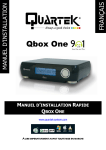
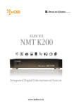
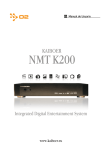
User manual MyiHome AirLinkWiFi Smurf A Series H.264 Internet Wireless Camera NIGHT VISION & REMOTE PAN/TILT ROTATE User Manual Version 2.0 FCC ID: AMU-A1 CE, R&TTE, ROHS User manual Application 1)"Baby monitor" Sweet BabyiCare *Watch, Sing, Talk & Hear baby * Anywhere & Anytime in the world Warning: All parents and caregivers to put at least 3 feet between any video or audio baby monitor cords and a child in a crib 2) Security MyiHome Real Time Security & Control anytime anywhere 3) Health Care 4) Pet care 5) Farm care Important Safeguards and Warnings >Environment:Please place and use IP camera under temperature between-10~60 degree and humidity less than 90%;Do not use IP camera in smoky or dusty environment; >Avoid collision or strong fall. Please insure the IP Camera level installation in a stable workplace. Please install in ventilated place. Keep the vent clean. Use within the rating input and output scope. >Do not touch the lenses of the IP Camera at will. The optimum focus range has been set as default. If you turn the lens, it may cause incorrect focus and vague images. >Do not turn the Pan/Tilt by force for it may cause damage to internal components of the Pan/Tilt. User manual 1 Introduction 1.1 Packing List When you receive internet wireless camera, Firstly, check model item on product is the same as what you ordered; Untie the packing and checking the items contained against the following list; Wireless IP Camera 1 Wi-Fi Antenna(If support in wireless) 1 DC Power Supply 1 CD 1 Network Cable 1 Mounting bracket 1 NOTE: Contact us immediately in the case of any damaged or short of contents. 1.2 Product views I/O PINS: 1 Output (+5V) 2 Output B 3 Alarm input 4 Input (GND) User manual Power: Outdoor Output (+12V2A) 1.3 PC System Requirements System configuration requirements :( Example for view four IP Camera) CPU: 2.06GHZ or above Memory: 256M or above Network Card: 10M or above Display Card: 64M or above memory Recommendable Operating system: Window2000 or Window XP or Vista 1.4 Hardware Instruction Follow the steps below to set up your camera hardware. Make sure to follow each step carefully to ensure that the camera operates properly 1) Plug the network cable into the camera and then into your Cable/DSL router. 2) Plug the power adapter into the camera and then into the power outlet. User manual CAUTION: Make sure to only use the power adapter supplied with IP Camera. Using a non-approved power adapter may damage the camera. 3) The camera takes approximately 30 seconds to start up. 4) When the camera is powered and network cable plug correctly. Its head will turn around and the Network Indicator LED is blank. 2 Functions >Real-time surveillance >Storage >Compression format >Backup >Video playback function >Network operation function >Alarm linkage function >Telecom interface 3 Software installation User manual Software installation is the key to the successful use of this product. 1 Open the CD, find the software as instruction; 2 Double click AirLink CMS setup.exe and install the software as instruction. Default IP address : 192.168.1.10 , subnet mask : 255.255.255.0 , gateway:192.168.1.1 default login: “admin” and password blank For safety sake, when firstly log-in, please go to “Account” to modify user name and password 3.1 CMS Instructions in Local network Click CMS icon -> 3.2 Add IP Camera at “System->Device Manager” 3.3 Device manager ->click Add area -> Zone List User manual 3.4 Zone List -> IP address is your local AP DHCP Client Range: For Example: Your AP Router IP address is 192.168.1.1, the DHCP range you can give at 192.168.1.200 3.5 IP Search Click -> Give any word for your Device name ->Select IP Address ->Click ->IP Search after 20 seconds will auto appear your device IP address User manual Please note: User Name default is admin, no Password; Port number should set at “34567” Click IP address from top list Click ->Add Device -> OK as below image 3.6 Device Monitor 3.6.1 End a list showed Devices Connect Successful 3.6.2 Monitor can be viewing maximum 64 channels 3.6.3 Right side has PTZ adjusted button and others functions button User manual 3.7 Record 3.7.1 Recording Storage setting ->Click -> Auto storage list as below image choose what you wish 3.7.1 Record Plan -> -> given a recording User manual schedule 3.7.2 Select cameras list from left side ->Click from Plan Template list add schedule 3.7.3 Select “Remote Playback” or “Local Playback” User manual Device add “By Name” or “By Time” at left side ->Search -> Auto Recording files appear in a list 【Playback control button】see detail in below chart; 3.8 Remote Configure 3.8.1 Remote Networking by DDNS domain name Click -> -> -> -> Click DDNS User manual User and Password: the user name and password used when applying for the domain name or use free myihome.org login account and password at each MyiHomeAirLink camera base paste up with a label Apply DDNS “myihome.org” as below image 3.8.2 WiFi Setting 3.8.3 Remote viewing how to set up from your AP Router 3.8.3.1 Give DHCP Client Range suggest setting at 192.168.1.100~200 User manual 3.8.3.2 Enable “UPNP” from TCP/IP Setting 3.8.3.3 Enable “DMZ” from Firewall setting giving a Host IP Address as below image User manual 3.8.3.4 Port Forwarding set up as below image, Remark: 34567 is media port : 34599 for 3G smart mobile phone remote viewing : 8188 is for viewing at IE, default is 80 User manual 3.9 Remote Viewing via 3G Smart Phone 3.9.1 Search from iPhone / iPad Apple APP Store: “AirLink WiFi Networking Corp.” or “MyiHome AirLinkWiFi.H.264” Process: Device Name: any word you like Address: 012059035.myihome.org (according to each IP camera myihome.org user account or you can use static IP address) Port: 34599 by fixed. User ID: default is “admin” Password: default is blank Max Channel: 1 (for camera 1, channel 2 for camera 2) 3.10 Remote control CMS 3.10.1 Click -> 3.10.2 Add Zone name Select top list, click -> -> Modify Zone name as below image 3.10.3 Appear at left list -> Select “Domain” add domain at “user account. myihome.org” -> click “Add Device” auto in left list. Now you can remote viewing and control by Out LAN Caution: The Network is not same as your IP Camera Local Area Network (LAN) User manual Main menu guideline Main Menu Submenu Function summary Record Record Set record config, record type, record period, etc. User manual Snapshot Set snapshot period, type , etc. Set motion detect alarm channel, sensitivity, Video motion area, linkage parameters: alarm output, snapshot, recording, PTZ, email sending, ftp upload, etc. Set video blind alarm channel, sensitivity, linkage Video blind parameters, alarm output, snapshot, recording, PTZ, email sending and ftp upload, etc. Set Alarm Video lost video lost parameters: alarm alarm channel output, and linkage recording, snapshot, PTZ, Email sending, FTP upload, etc. Set alarm input channel and linkage parameters: Alarm input alarm output, recording, snapshot, PTZ, email sending, FTP upload, etc. Alarm output Set alarm mode: configuration, manual, stop Storage device not exist, not enough space, Abnormal access storage device fail, IP conflict, network abnormal alarm Set system time, data format, language, hard General disk full time operation, machine number, video format, output mode, summertime, stay time System Set encode mode: encode mode, resolution, Encode frame rate, bit rate, image quality, code stream value; I frame interval parameter, video/audio enable. User manual Set basic net parameter, and DHCP 、 DNS Network parameter , auto-gain IP address, network high-speed download, net transmission tactics ARSP、Mobile monitor、UPNP、FTP、WiFi、3G、 Net service alarm center 、 RTSP 、 PPPOE 、 NTP 、 Email 、 IP authority、DDNS parameter, etc. GUI display PTZ Config RS485 RS232 Set channel title, cover area, time title, channel time overlap and position Set channel, PTZ protocol, address, baud rate, data bit, stop bit, parity Set protocol, address, baud rate, data bit, stop bit, parity Set serial port function, baud rate, data bit, stop bit, parity Exposure mode, Day/Night mode, Backlight Camera compensation, Auto iris, profile, AE reference, parameter AGC, slow shutter, IR_CUT, Image、Over-turn、 anti-flicker etc Do operation to TF card, such as set read/writ, HDD Manage read only, redundant, format disk, recover, partition, etc. Advanced Account Auto maintain Modify user, group or password. Add user or group. Delete user or group. Set auto reboot system, time to auto delete file User manual Restore setting status of : regular, encode, Default record, alarm, network, net service, GUI display, serial settings, account manage Import & Export Upgrade Reboot HDD info Info Log Version Config import, Config export, Log export To do net upgrade via IE or client software IPC soft reboot Show ttl space of HDD, type, space left, record time, etc Can base on record type and time to search log, can clear the log information Show alarm input output, system version, build date, etc Camera hardware notification: . Power Port: DC power supply Status Indication Light: . Red - power on or alarm activated . Green - normally Working or Record . Alarm Input: normal open(default) and close . Alarm Output: alarm activated output . RS485: PTZ or other RS485 devices . Reset: Press on 5 seconds to reset to factory default settings, include IP settings Audio Input: connect with audio picker . Audio Output: connect with speaker . Video Output: BNC/TV output, use for adjust camera and view IP settings