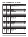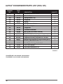
1
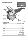
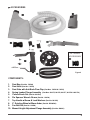
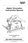
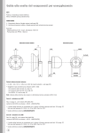
MANUAL Alpha® Ecogrinder Instruction Manual VERSION 5 Part No: ECG-125 ECG-225 103 Bauer Drive, Oakland, NJ 07436 • 800-648-7229 • Fax: 800-286-0114 www.alpha-tools.com TABLE OF CONTENTS Ecogrinder Overview................................................................................................. 4 Accessories............................................................................................................... 5 Introduction................................................................................................................ 6 About The Symbols............................................................................................. 6 Electrical Symbols............................................................................................... 6 General Safety Rules................................................................................................. 7 Work Area............................................................................................................. 7 Electrical Safety................................................................................................... 7 Personal Safety.................................................................................................... 7 Tool Use and Care................................................................................................ 8 Service.................................................................................................................. 9 Specific Safety Rules........................................................................................... 9 Use Proper Extension Cords............................................................................ 10 Grounding Instructions..................................................................................... 10 Additional Precautions For Using The Ecogrinder.............................................. 11 Safety Advice...................................................................................................... 11 How To Grind........................................................................................................... 12 How To Handle The Grinder.............................................................................. 12 Ecogrinder Operation.............................................................................................. 13 Main Connection................................................................................................ 13 Circuit Breaker................................................................................................... 14 Before Use................................................................................................................ 14 About Double Insulation.................................................................................... 16 Laws And Regulations Of Noise Levels........................................................... 16 Using The Tool ........................................................................................................ 16 Open Surface Grinding...................................................................................... 16 Edge Grinding.................................................................................................... 16 Dust Hose and Bag Installation.............................................................................. 17 Ecogrinder Maintenance ........................................................................................ 19 Daily..................................................................................................................... 19 Periodic............................................................................................................... 19 2 Bearings And Gears........................................................................................... 19 Replacing And Checking The Carbon Brushes.................................................... 20 Grinding Wheel Inspection, Removal, and Installation........................................ 24 Inspecting The Grinding Wheel........................................................................ 24 Checking The Grinding Wheel For Replacement............................................ 25 Removing The Grinding Wheel......................................................................... 26 Replacing the Grinding Wheel.......................................................................... 27 Installing The Spring Loaded Flange Assembly............................................. 28 Installing The Grinding Wheel.......................................................................... 29 Fan Belt Removal And Replacement..................................................................... 30 Testing The Unit For Flow................................................................................. 30 Inner Fan Belt Removal..................................................................................... 31 Inspecting and Cleaning The Fan Belts and Pulleys...................................... 32 Reinstalling The Inner Fan Belt........................................................................ 32 Removal Of The Outer Fan Belt........................................................................ 33 Reinstalling The Outer Fan Belt........................................................................ 34 Alpha® Ecogrinder Motor Schematic (ECG-125)................................................... 35 Alpha® Ecogrinder Attachment Schematic .......................................................... 36 Alpha® Ecogrinder Parts List (ECG-125)............................................................... 37 Services And Warranty Information....................................................................... 41 Loaner Program................................................................................................. 41 Need More Information ..................................................................................... 41 Warranty.............................................................................................................. 41 Alpha® Tool Repair Service............................................................................... 42 EC Declaration Of Conformity................................................................................ 43 Appendix A - Manual Height Adjustment Flange Assembly................................ 44 3 ECOGRINDER OVERVIEW Power Switch Lock Aux Handle Fan Case Power Switch Fan Belt Cover Slide Cover Knob Spindle Locking Pin Edge Grinding Slide Cover Protective Grinding Wheel Cover Dust Brush Figure-1 SPECIFICATIONS Power Supply..............................................................Single-Phase AC, 50/60 Hz Rating.................................................................................................110/220 Volts Amperage..................................................................................................10.25/5.1 Power............................................................................................................ 1050W No-load Speed.......................................................................................8,700 RPM Wheel Size.............................................................................................5” / 125mm Arbor.............................................................................................................. 26mm (To be used with Spring Loaded Flange Assembly and Drive Plate Adapter) Arbor................................................................................................7/8” / 22.23mm (To be used with Manual Height Adjustment Flange Assembly) Weight...................................................................................... 12.70 lbs / 5.76kgs (Tool w/Hose and Bag) Cord........................................................................................................... 10ft / 3m (Single Phase 2 Conductor) 4 ACCESSORIES OPTIONAL ACCESSORY Figure-2 COMPONENTS: 1. 2. 3. 4. 5. 6. 7. 8. 9. 10. Dust Bag (Part No. 133544) Dust Hose (Part No. 133533) Dust Gate with Anti-Back-Flow Flap (Part Nos. 133530 & 133531) Spring Loaded Flange Assembly (Part Nos. 801375, 801376, 801377, 801378 & 801379) Carbon Brush Set (Part No. 801594) Pin Spanner Wrench 34 mm (Part No. 130434) Top Handle w/Screw & Lock Washers (Part No. 801354) 5” Grinding Wheel w/26mm Arbor (Part No. DSQ0500) Fan Belt Set (Part No. 133508) Manual Height Adjustment Flange Assembly (Part No. 890001) 5 INTRODUCTION Thank you for purchasing the Alpha® Ecogrinder. Please read this instruction manual thoroughly to ensure safety and correct use of this tool. Keep this manual in a place where operators can access it easily whenever necessary. ABOUT THE SYMBOLS According tothe hazard level, all safety notes in this manual are classified into “DANGER”, “WARNING”, and “CAUTION”. DANGER! Death or serious personal injury is imminent when handling this grinder incorrectly. WARNING! There is a possibility of death or serious personal injury when handling this grinder incorrectly. CAUTION! There is a possibility of personal injury or property damage when handling this grinder incorrectly. NOTE: In some situations, failing to observe WARNING notes could result in death or serious personal injury. Be sure to read and observe the safety notes to ensure safety and correct use of the grinder. ELECTRICAL SYMBOLS The following show the symbols used for tool. V Volts A Amperes Hz Hertz ~ or a.c. Alternating Current n0 No load speed …/min Revolution or reciprocation per minute kg Kilograms 6 Protective Earth CAUTION! The following are important notes for products, operation, and maintenance applicable to this polisher. GENERAL SAFETY RULES • • • • • • • • • • WORK AREA Keep your work area clean and well lit. Cluttered benches and dark areas invite accidents. Do not operate power tools in explosive atmospheres, such as in the presence of flammable liquids, gases, or dust. Power tools may create sparks which may ignite the dust or fumes. Keep bystanders, children, and visitors away while operating a power tool. Distractions can cause you to lose control. ELECTRICAL SAFETY Grounded tools must be plugged into an outlet properly installed and grounded in accordance with all codes and ordinances. Never remove the grounding prong or modify the plug in any way. Do not use any adaptor plugs. Check with a qualified electrician if you are in doubt as to whether the outlet is properly grounded. If the tools should electrically malfunction or break down grounding provides a low resistance path to carry electricity away from the user. Avoid body contact with grounded surfaces, such as pipes, radiators, ranges, and refrigerators. There is an increased risk of electric shock if your body is grounded. Don’t expose power tools to rain or wet conditions. Water entering a power tool will increase the risk of electric shock. Do not abuse the cord. Never use the cord to carry the tools or pull the plug from an outlet. Keep cord away from heat, oil, sharp edges, or moving parts. Replace damaged cords immediately. Damaged cords increase the risk of electric shock. When operating a power tool outside, use an outdoor extension cord marked “W-A” or “W”. These cords are rated for outdoor use and reduce the risk of electric shock. PERSONAL SAFETY Stay alert, watch what you are doing and use common sense when operating a power tool. Do not use tool while tired or under the influence of drugs, alcohol, or medication. A moment of inattention while operating power tools may result in serious personal injury. Dress properly. Do not wear loose clothing or jewelry. Contain long hair. Keep your hair, clothing, and gloves away from moving parts. Loose clothes, jewelry, or long hair can be caught in moving parts or drawn into air vents. 7 • • • • • • • • • • • • 8 Avoid accidental starting. Be sure switch is off before plugging in. Carrying tools with your finger on the switch or plugging in tools that have the switch on, invites accidents. Remove adjusting keys or wrenches before turning the tool on. A wrench or a key that is left attached to a rotating part of the tool may result in personal injury. Do not overreach. Keep proper footing and balance at all times. Proper footing and balance enables better control of the tool in unexpected situations. Do not use on a ladder or unstable support. Use safety equipment. Always wear eye protection. Dust mask, nonskid safety shoes, hard hat, or hearing protection must be used for appropriate conditions. TOOL USE AND CARE Use clamps or other practical way to secure and support the workpiece to a stable platform. Holding the work by hand or against your body is unstable and may lead to loss of control. Do not force tool, use the correct tool for your application. The correct tool will do the job better and safer at the rate for which it is designed. Do not use tool if switch does not turn it on or off. Any tool that cannot be controlled with the switch is dangerous and must be repaired. Disconnect the plug from power source before making any adjustments, changing accessories, or storing the tool. Such preventive safety measures reduce the risk of starting the tool accidentally. Store idle tools out of the reach of children and other untrained persons. Tools are dangerous in the hands of untrained users. Maintain tools with care. Keep tools sharp and clean for better and safer performance. Follow instructions for lubricating and changing accessories. Inspect the electrical cord periodically and if damaged, have it repaired by authorized service facility. Inspect extension cords periodically and replace if damaged. Keep handles dry, clean and free from oil and grease. Check for damaged parts. Before using the tool each day, a guard or other part that is damaged should be carefully checked to determine that it will operate properly and perform its intended function. Check for alignment of moving parts, breakage of parts, mounting, and any other conditions that may affect its operation. A guard or other part that is damaged should be properly repaired or replaced by an authorized service center unless otherwise indicated elsewhere in this instruction manual. Have defective switches replaced by authorized service center. Do not use the tool if it cannot be turned on and off by the switch. Use only accessories that are recommended by the manufacturer for your model. Accessories that may be suitable for one tool, may become hazardous when used on another tool. • • • • • • • • • • • • • SERVICE Tool service must be performed only by qualified repair personnel. Service or maintenance performed by unqualified personnel could result in a risk of injury. When servicing a tool, use only identical replacement parts. Follow instructions in the Maintenance section of this manual. Use of unauthorized part or failure to follow Maintenance Instructions may create a risk of electric shock or injury. SPECIFIC SAFETY RULES Accessories must be rated for at least the speed recommended on the tool warning label. Wheels and other accessories running over rated speed can fly apart and cause injury. Hold tool by insulated gripping surfaces when performing an operation where the cutting tool may contact hidden wiring or its own cord. Contact with a “live” wire will make exposed metal parts of the tool “live” and shock the operator. Know your power tool. Read operator`s manual carefully. Learn its application and limitations, as well as the specific potential hazards related to this tool. Following this rule will reduce the risk of electric shock, fire, or serious injury. Always wear safety glasses with side shields. Everyday eye-glasses have only impact resistant lenses; they are NOT safety glasses. Protect your lungs. Wear a face or dust mask if the operation is dusty. Protect your hearing. Wear hearing protection during extended periods of operation. Inspect tool cords periodically and if damaged, have repaired at your nearest Factory Service Center or other Authorized Service Organization. Constantly stay aware of cord location. Check damaged parts. Before further use of the tool, a guard or other part that is damaged should be carefully checked to determine that it will operate properly and perform its intended function. Check for alignment of moving parts, binding of moving parts, breakage of parts, mounting, and any other conditions that may affect its operation, A guard or other part that is damaged should be properly repaired or replaced by an authorized service center. Do not abuse cord. Never carry the tool by the cord or yank it to disconnect it from the receptacle. Keep cord away from heat, oil, and sharp edges. Following this rule will reduce the risk of electric shock or fire. Make sure your extension cord is in good condition. When using an extension cord, be sure to use one heavy enough to carry the current your product will draw. An undersized cord will cause a drop in line voltage resulting in loss of power and overheating. Inspect for and remove all foreign objects from workpiece before polishing. Follow this rule will reduce the risk of serious personal injury. 9 • Drugs, alcohol, medication, Do not operate tool while under the influence of drugs, alcohol, or any medication. Follow this rule will reduce the risk of electric shock, fire, or serious personal injury. Keep hands away from polishing area. Follow this rule will reduce the risk of cuts, scrapes, or serious personal injury. Save these instruction. Refer to them frequently and use them to instruct others who may use this tool. If you loan someone this tool, loan them these instructions. • • USE PROPER EXTENSION CORDS Use only three-wire extension cords that have three-prong grounding-type plugs and three-pole receptacles that accept the tool’s plug. Make sure your extension cord is in good condition. Replace or repair damaged or worn cord immediately. When using an extension cord, be sure to use one heavy enough to carry the current your product will draw. An undersized cord will cause a drop in line voltage resulting in loss of power and overheating. Below table shows the correct size to use depending on cord length and nameplate ampere rating. If in doubt, use the next heavier gauge. The smaller the gauge number, the heavier the cord. Ampere Rating Total length of cord in feet (120V ) 25ft More Than Not More Than 50ft 100ft AWG 0 6 18 16 16 6 10 18 16 14 10 12 16 16 14 12 16 14 12 Not Recommended GROUNDING INSTRUCTIONS This tool should be grounded while in use to protect the operator from electric shock. The tool is equipped with a three-conductor cord and three-prong grounding type plug to fit the proper grounding type receptacle. The green (or green and yellow) conductor in the cord is the grounding wire. Never connect the green (or green and yellow) wire to a live terminal. 10 ADDITIONAL PRECAUTIONS FOR USING THE ECOGRINDER In addition to the general safety notes described on the preceding pages, please read and observe the following precautionary notes before using the Ecogrinder. DANGER! • • • • • • • • • • • • • • • SAFETY ADVICE Please note safety instructions on Page 3-5. Do not pierce the motor housing as this could damage the double insulation. Always remove plug from the outlet before making any changes to the settings or performing maintenance. Ensure the tool is switched off prior to plugging in. Keep power cable clear from working area of the machine. The power cable should always lead away from you and behind the operating area. Before use, check the machine, cable and plug for any damages or material fatigue. Only authorized service agents should perform repairs. After switching off, the machine will not idle down immediately. Allow the machine to come to a complete stop before putting it down. Always wear safety glasses and ear protection when working with this machine. It is further recommended to wear safety gloves, apron, as well as sturdy non-slipping shoes. Only use grinding wheels whose permitted speed is at least as high as the highest no-load speed of the machine. Be sure wheels fit tool properly and securely. Do not modify the tool to force fit the wheel. Do not remove wheel cover. Check grinding tools before use. The grinding wheel must be properly mounted and turn freely. Perform a test run for at least 30 seconds without any load. Do not use damaged, out of round or vibrating grinding tools. Immediately switch off the machine in case of considerable vibrations or if other malfunctions occur. Check the machine in order to find out the cause. Always use and store the grinding wheels according to the manufacturer’s instructions. The flange bolt must be tightened before starting to work with the machine. The work piece must be secured if it is not heavy enough to prevent movement. Do not use emery wheel. 11 HOW TO GRIND WARNING! 1. During operation, be sure to wear safety glasses and hearing protection. 2. Some dust created when using this grinder contains chemicals known to cause cancer, birth defects or other reproductive harm. Some example of these chemicals are: a. Lead based paints b. Crystalline silica found in cement, bricks and other masonry products c. Arsenic and chromium coming from pressure treated wood d. Pesticides and other chemicals that could have been applied to the work area 3. An approved dust mask that protects the operator against these chemicals should be worn at all times. These dust masks are designed to filter out microscopic particles. DANGER! 1. If you accidentally drop the machine, do not use until checking that the machine and grinding wheel are not cracked, deformed, or damaged. 2. Grinding wheels used on this tool should be rated at or above the no load rating marked on this tool. Running grinding wheels over their rated speeds can fly apart and cause injury. CAUTION! 1. Do not press the lock pin while the wheel is rotating. 2. Do not turn the switch on with the lock pin pressed down. HOW TO HANDLE THE GRINDER 1. It is not necessary to apply more force onto the machine than the force created by the weight of the machine itself. 2. Applying excessive force may damage the grinding wheel and burn up the motor. Such action may decrease the rotation speed which reduces the efficiency of dust suction, because its power is driven by the spindle. 3. When used properly the unit should float on top of the brush ring, if excessive force is applied the brush will be crushed and wear out. 4. Hold the tool with both hands while starting; the torque from the motor will cause the tool to jerk. 5. The motor and vacuum system should be running at full speed before applying it to the work surface. 6. When the grinding wheel first comes into contact with the work surface or when the wheel is new, make contact slowly. 7. Keep moving the tool in a circular motion to prevent grooving in the work surface. 12 8. Hold the unit tightly to prevent it from walking, and remove the high spots in the work surface from the top down. 9. This grinder is designed to be used dry, if the surface is wet the dust will not be able to pass through the fan and a breakdown will result. ECOGRINDER OPERATION CAUTION! Always be sure that the tool is switched off and unplugged before adjusting or checking function on tool. MAIN CONNECTION Connect only to single-phase AC current supply and only to the main voltage specified on the rating plate. SWITCHING ON AND OFF CAUTION! Before plugging in the tool, always check the working voltage and be sure that the voltage specified is on the name plate. Before plugging in the tool, always check to see that the trigger switch actuates properly and returns to the “OFF” position. Switching on and Off: Intermittent Use: Switching on: Press the trigger switch Switch off: Release the trigger switch Locking Button On/off Switch and Locking Button Continuous Use: Switching on: Press the trigger switch and then the locking button, then release the trigger switch Switching off: press the trigger switch, then release On/Off Trigger Switch Figure-3 13 CIRCUIT BREAKER CAUTION! If the tool stops during operation you need to switch the unit off before resetting the circuit breaker. Resetting the circuit breaker with the trigger lock on can cause an accident. Note: If the circuit breaker stops the tool repeatedly, this could be an indication that excessive pressure is being applied to the tool, slowing the motor and causing it to overheat. Use less force and allow the tool to do the work. The circuit breaker can also trip, if the carbon brushes are completely worn and need to be replaced. The Ecogrinder is supplied with an in-line circuit breaker. In the event that the breaker is tripped, push the button to reset. Once you are able to reset the circuit breaker, run the tool in a no-load condition allowing air to pass over the motor and cool it down. Reset Button In-line Circuit Breaker Figure-4 BEFORE USE DANGER! Before using the machine, check the following items. In particular, check items 1 to 5 before plugging the power supply cord into the power outlet. 1. Check the working voltage. – Be sure the voltage specified on the rating plate is the voltage available at the power outlet. If the machine is used with higher voltage than specified, the motor will burnout. Any attempts to do so may damage the polisher and/or cause an accident. 14 2. Make sure the ON/OFF switch is off. – If you plug in the power supply cord without realizing that the switch is ON, the machine will start and may cause an accident. Make sure the on/off switch trigger is out and the locking button is not engaged. 3. Inspect the protective wheel cover. – Do not remove the wheel cover. It will protect you if the grinding wheel breaks. – Be sure to firmly attach the grinding wheel or any optional accessory. 4. Inspect the grinding wheel. – Check if you have a specified wheel. – Never use cracked, chipped, or any damaged wheels. – Follow the procedures specified in the instruction manual to properly attach applicable accessories. 5. Check the power outlet. – When the plug of the power supply cord is easily pulled out of the power outlet, the outlet should be replaced. For such task, consult an electrician. If the power outlet is used on a continuous basis, it may overheat and cause accidents. 6. Perform test runs. WARNING! 1. Before turning the switch ON, make sure the rotating parts are not touching anything. If the switch is turned ON while they are in contact with anything else, the wheel may get damaged and may cause injuries. 2. When a new wheel is attached and the switch is turned ON, keep your body well away from the exposed sides of the wheel for a moment until the machine reaches its full speed. It is very dangerous to perform grinding operations using cracked, chipped or damaged wheels. Before starting grinding operations, keep the wheel away from anyone nearby. Be sure to perform a few test runs to check whether there are any abnormalities. Test run duration: • After replacing a wheel..........……………………at least 3 minutes • Before starting operations each day...................at least 1 minute 15 ABOUT DOUBLE INSULATION This machine is designed with double insulation. Two insulations are used between the conductor and the outer body of the machine. An electric machine with the double insulation highly improves safety from electric shocks. Do not attach or replace unspecified parts and do not assemble incorrectly. This may cause the insulation to malfunction. LAWS AND REGULATIONS OF NOISE LEVELS Please observe local laws and regulations regarding noise level in order to avoid disturbing surrounding areas. Install a soundproof wall if required to comply with the local laws and regulations. USING THE TOOL OPEN SURFACE GRINDING Under normal operation, the slide cover assembly should remain in the closed position, shielding the grinding wheel inside the protective housing. (See Figure 5) Slide Locking Knob Nut Slide Cover Assembly Closed/Open Slide Cover Assembly closed Slide Cover Assembly open Figure-5 Figure-6 EDGE GRINDING CAUTION! When you grind close to a wall, turn the locking knob nut counter clockwise to loosen and slide the cover all the way open. Turn the locking knob nut clockwise to tighten. When edge grinding and the slide cover assembly is open, the front of the tool should be held against the wall to contain the dust and small fragments inside of the protective wheel cover. Caution should be taken because small fragments can rebound off of the wall into the operator. 16 With the slide cover assembly open, the unit can now be pushed up against the wall allowing the housing to ride along the edge. (See Figure 6: Slide Cover Assembly Open). With the slide cover assembly open, extra care should be taken to hold the unit flat to prevent grooving along the wall. Edge Grinding / 1mm Wall Clearance 1mm Figure-7 Edge grinding will work best with our 5” grinding wheel. This configuration allows you about 1mm clearance between the grinding wheel and the wall. DUST HOSE AND BAG INSTALLATION 1. Install the back-flow preventer assembly to the Ecogrinder exhaust port, with the dust gate in the upright position, so flap will close when the tool is turned off. Back-Flow Preventer w/Dust Gate Dust Gate Figure-8 Back Flow Preventer Assembly and Dust Hose 2. Slide the dust hose onto the backflow preventer assembly, twist and turn until the hose is up against the shoulder of the back-flow preventer assembly. Dust Hose Figure-9 Back-flow Preventer Assembly Shoulder 17 Hook & Loop Strap 3. With the dust hose attached to the tool, you can now install the dust bag onto the dust bag holder. Dust Bag Holder and Dust Bag Dust Bag Hose Shoulder Dust Bag Holder Raised Lip Figure-10 Hose Fitting with Hook & Loop Strap Secured 4. Open up the hook and loop strap and slide the hose end into bag until the end of the bag is even with shoulder on the hose end. Tighten the hook and loop strap so the strap is behind the raised lip on the hose fitting. Figure-11 5. When in use, the dust bag and hose should lie flat on the ground. When the bag is new it will not inflate immediately. As the pores in the bag become clogged, the bag will start to inflate. Note: As the bag fills up and creates backpressure, the suction will decrease. When dust is not being removed from the work surface, you should check the fan belts and/or replace the bag. Dust Bag Figure-12 18 ECOGRINDER MAINTENANCE DAILY 1. Before daily start-up inspect grinder, power cord, circuit breaker assembly, and grinding wheel looking for chips and cracks. Inspect the dust bag for holes or if it is full and needs to be replaced. 2. If damage has occurred, repair affected areas before use. 3. Turn the unit on to ensure that the fan is running and the dust bag is inflating. A new bag will not inflate until the pores in the material start to fill with stone dust. 4. After daily use of the tool, clean and blow off the exterior of tool and around air intake vents on rear handle. PERIODIC WARNING! Preventive maintenance performed by unauthorized personnel may result in misplacing of internal wires and/or components which voids the warranty and could cause serious hazards. We recommend that tool service and repairs not covered in the manual be preformed by an Alpha® Authorized Repair Center. Periodic maintenance is done to check the tool and to minimize down time. These checks are done based on hours of operation and operating conditions. Operating conditions can vary depending on the work surface and job being preformed. If the tool is not used for a long period of time, the carbon brushes should be checked and the commutator cleaned, before putting the tool back into operation. BEARINGS AND GEARS To minimize your tool’s down time and expensive tool repairs, it is recommended to send the tool back to an Alpha® Repair Center after about 300 to 400 hours of operation or every second carbon brush change. The bearings should be replaced and the gears should be checked. If your tool starts to sound differently, this could be an indication of a worn bearing. Continuing to use the tool in this condition could result in overheating or motor failure. 19 REPLACING AND CHECKING THE CARBON BRUSHES In order to keep your tool running correctly, you need to check your carbon brushes after every one hundred hours of use. Carbon brushes wear out over time based on the grinder’s usage. If a carbon brush is worn out, it may cause the motor to malfunction or fail to run. The carbon brushes should be replaced before the twisted wire reaches the bottom of the slot. DANGER! Be sure to unplug the power cord from the outlet before servicing the unit, to prevent electrical shock or starting the tool accidentally. 1. Remove the four self-tapping Phillips screws holding on the rear handle. Handle Removal / Selt-tapping Screws 4 Self-tapping Screws in handle Figure-13 2. Split handle and turn it on its side to get access to the carbon brush holder. Remove the small Phillips screw to remove the carbon brush holder. Carbon Brush Carbon Brush Assembly Parts Motor Housing Coil Spring Phillips Screw 20 Figure-14 Carbon Brush Holder 3. Using small needle nose pliers, gently pull the carbon brush holder straight out from the motor housing. After removing the carbon brush holder from the motor housing, you need to remove the power wire terminal from the carbon brush holder (Note: the path of the wire, as it is important for reassembly of the unit). The carbon brush holder assembly is now free from the machine and can be inspected. Carbon Brush Removal Power Wire and Terminal Figure-15 4. Pictured on the left below, is a worn carbon brush in the holder (Note: the twisted wire is at the end of the slot and the carbon brush is almost flush with holder). On the right below, is a new carbon brush in the holder. Worn and New Carbon Brushes New Worn Figure-16 NOTE: Carbon brushes sometime wear at different rates; however, both carbon brushes should be replaced at the same time. The carbon brushes in this grinder are located under the rear handle. WARNING! Replacing the carbon brushes in this unit with non-Alpha® parts could damage the unit, and will void the warranty. 21 5. The carbon brush can be removed from the holder by pulling back the carbon brush spring and moving it to the side as shown in the photo on the left below. After reassembly, press the carbon brush in and out of the holder to make sure it moves freely and the twisted wire is not hitting the wire terminal or spring (see photo below on right). Removing and Installing the Carbon Brush Carbon Brush Spring Figure-17 Twisted Wire 6. Remove the old carbon brush and disconnect the wire terminal. If the inside of the holder is filled with dust, clean it before installing the new carbon brush. Upon installation of the new carbon brush, make sure the twisted wire is in the slot and behind wire terminals on the holder (as in the above right photo). 7. With the carbon brush holder removed, you can check and clean the armature commutator. The commutator is the contact points that the carbon brushes ride on when the motor is running. 8. The commutator should be clean and shiny. If it is dull and black, you can clean it with a commutator cleaning stone. Clean and Dirty Commutator Clean Dirty Figure-18 22 Figure-19 9. To clean the commutator, press the commutator cleaning stone against the commutator and rotate the armature by turning the spindle shaft by hand. Continue for a minute or until the commutator is clean and shiny. Cleaning the Commutator Figure-20 10. Reconnect the power wire, insuring that the wire path is correct (See figure 15), Reinstall the carbon brush holder into the slot on the motor housing and slide in until the screw tab hits the stop, then install the screw using light pressure to prevent it from stripping. Note: All electric tools have two carbon brushes located on opposite sides of the tool. Turn the tool over and replace the carbon brush on the other side following steps 2-10 again. 11. After both carbon brushes have been replaced, you can reassemble the rear handle assembly. The switch side should be installed first. Make sure the power wires are in the slot above the soft starter assembly and the soft starter assembly is in its holder to prevent the pinching of the wire. Reassembling the Handle Wire slot Soft Starter Assembly Figure-21 12. Hand-tighten the four self-tapping screws in the handle to prevent them from stripping (see figure 13). 13. With the tool reassembled, perform the daily maintenance and run the tool in a no-load condition for a couple of minutes to re-seat the carbon brushes. 23 GRINDING WHEEL INSPECTION, REMOVAL, AND INSTALLATION DANGER! Be sure to unplug the power cord from the outlet before attaching or removing the grinding wheel from the tool. Accidental starting of the motor may cause bodily injury. WARNING! Be sure to securely tighten the flange assembly and all loose screws before testing the unit. Please allow the grinding wheel to do the work. It is not necessary to apply more force onto the machine than the force created by the weight of the machine itself. Applying excessive force may damage the grinding wheel and cause premature failure of the bearings and gears. Such action may decrease the rotation speed of the of the motor which reduces the efficiency of the dust suction, because its power is driven by the spindle. INSPECTING THE GRINDING WHEEL 1. If you are reinstalling the grinding wheel, check the welds on the diamond segments for cracks. 2. Check the diamond segments for even wear. 3. The grinding wheel should be replaced if you find a crack in the weld or if the diamond segments are worn down and below the brush assembly. 26mm Arbor Grinding Wheel w/ Drive Plate Adapter Attached Diamond Segment Drive Plate Adapter Wheel Figure-22 NOTE: The Alpha® 26mm arbor grinding wheel, drive plate adapter and spring loaded flange assembly are designed and engineered to work together. This design eliminates the need for adjusting the grinding wheel height as the diamond segments wear. 24 CHECKING THE GRINDING WHEEL FOR REPLACEMENT 1. The grinding wheel and spring loaded flange are designed to be self-adjusting. The grinding wheel should float on the flange nut allowing it to adjust to the height of the brush assembly. 2. The grinding wheel should be replaced when the diamond segments are worn down close to the hub and there are no visible diamond chips. 3. You also need to check the grinding wheel and diamond segments for chips, cracks in the welds, or missing segments. 4. Continuing to use the grinding wheel when it is in need of replacement will prematurely wear out the brush assembly and the system will not work efficiently. Diamond Segments Checking the Grinding Wheel Diamond Segments Welds Figure-23 Figure-24 DANGER! Do not use a grinding wheel that is chipped, cracked or missing diamond segments. 25 REMOVING THE GRINDING WHEEL 1. While pressing in on the spindle lock button, turn the grinding wheel by hand until the lock can fully engage. Spindle Lock Button Figure-25 2. With the lock fully engaged, turn the flange bolt counter clockwise to loosen the flange bolt with the flange wrench. Loosening the Flange Bolt Figure-26 3. If the grinding wheel is turning during removal, then the flange nut is unscrewing off the spindle. Remove the complete flange assembly. With the flange assembly removed use a 24mm or adjustable wrench and the flange wrench to remove the flange bolt from the flange nut. 26 REPLACING THE GRINDING WHEEL 1. To replace the grinding wheel follow the steps for removing the grinding wheel (see page 26). After the grinding wheel is removed, you need to remove the three flat-head screws holding the drive plate adapter onto the diamond grinding wheel. Note: When you purchase a replacement Grinding Wheel (Part # DSQ0500), it does not come with the Drive Plate Adapter (Part # 801381) or Flat Head Screws (Part # 801382). These parts need to be ordered separately or re-used if still in good condition. Grinding wheel, adapter and screws Grinding Wheel (26mm Arbor) Flat Head Screws (M4x6) Drive Plate Adapter Figure-27 2. Clean the inside of the Drive Plate Adapter and check for wear. If the square arbor is worn, it will prevent the grinding wheel from floating on the flange nut, and should be replaced. 3. Place the Drive Plate Adapter onto the new Diamond Grinding Wheel and align the holes. A small drop of Loctite thread lock should be applied to each screw to keep it from loosening. Tighten each screw until seated, then go back around and re-tighten each screw to secure them evenly. 4. The new Diamond Grinding Wheel can now be reinstalled on the tool. 27 INSTALLING THE SPRING LOADED FLANGE ASSEMBLY NOTE: This unit comes equipped with a self-adjusting spring loaded flange assembly. This flange assembly allows the grinding wheel to adjust as it wears to keep positive contact with the work. 1. With the inner fan belt and cover installed, you can now install the spring loaded flange and grinding wheel. 2. Install the lower spring retainer, spring, and upper spring retainer. Spring Loaded Flange Assembly Upper Spring Retainer Flange Nut Figure-28 Figure-29 Lower Spring Retainer Spring Note: The Spring Loaded Flange Assembly only works with the 26mm arbor grinding wheel (DSQ0500) and the drive plate adapter. A 7/8” round hole arbor will just spin on the flange nut. 28 INSTALLING THE GRINDING WHEEL 1. Place the grinding wheel and flange bolt on the spindle. Flange Bolt Grinding Wheel and Flange Bolt Grinding Wheel Figure-30 2. While pressing in on the spindle lock button, turn the grinding wheel by hand until the lock is fully engaged. Spindle Lock Button Figure-31 Tighten the Flange Bolt 3. With the lock fully engaged, turn the flange bolt clockwise to tighten with the flange wrench. Figure-32 4. With the flange bolt and nut tightened, check and make sure the grinding wheel moves freely up and down on the flange nut. 5. Plug the unit in and test run to check for balancing before starting to grind. 29 FAN BELT REMOVAL AND REPLACEMENT The Ecogrinder incorporates two drive fan belts (an inner and an outer) to power the fan assembly. If the unit is not removing the dust, you will need to inspect the fan belts, fan assembly, and dust bag to find the cause of the problem. NOTE: This Ecogrinder makes use of a flat fan belt and pulley system that is self-centering due to the barrel shape of the pulleys. If the fan belt is worn or dirty it can rotate off the pulleys, this will be indicated by a loss of suction. TESTING THE UNIT FOR FLOW 1. A simple test can be done to see if the fan unit is working correctly. 2. Disconnect the hose and back-flow preventer from the tool and stand the grinder up so it is resting on the protective housing and the top handle. Point the fan exhaust in a direction away from you or anyone else. 3. Turn the unit on and hold a piece of paper over the exhaust port. Paper should extend and stand up straight when unit is turned on. .. Fan Unit Test OFF Figure-33 ON Figure-34 4. If the test indicates a weak or no flow condition, the fan belts, pulleys, and fan unit will need to be checked to find the cause of the problem. 30 INNER FAN BELT REMOVAL DANGER! Be sure to unplug the power cord from the outlet before assembling or disassembling the tool. Accidental starting of the motor may cause bodily injury. 1. Remove the grinding wheel and flange assembly (See section for grinding wheel and flange installation and removal) 2. Remove the Phillips screw used to secure the inner fan belt cover. Remove the inner fan belt cover to expose the inner fan belts and pulleys. Inner Fan Belt Cover Inner Belt Cover Phillips Screw Figure-35 3. Remove the inner fan belt by grabbing it with your thumb and index finger and pulling it up while rotating. It could take two or three turns to remove the fan belt. Fan Belt Removal Figure-36 31 INSPECTING AND CLEANING THE FAN BELTS AND PULLEYS 1. With the fan belt removed, you can now check and clean it using a mild detergent. The fan belt will need to be replaced if it is frayed or showing signs of wear. 2. The pulley should also be cleaned with a mild detergent. 3. Rotate the pulley by hand to check for bearing play and wear. 4. Make sure to fully clean the inside area of the large pulley where the pulley meets the spindle to prevent slippage. Cleaning fan belt and pulleys Clean the dust and buildup in this recessed area before reinstalling. Figure-37 REINSTALLING THE INNER FAN BELT 1. Reinstall the bottom pulley with the recess facing the spindle and housing (see figure 38). Press the spindle lock button (see figure 25) while installing the flange nut and lock in place. 2. Place the fan belt around the top of the large pulley, guide the other side of the belt against the small pulley with your index finger while turning the flange nut. After two or three turns the fan belt should center itself. Inner fan belt Installation Figure-38 3. Reinstall the inner fan belt cover and flat head screw. 32 REMOVAL OF THE OUTER FAN BELT 1. Remove the knob bolt and outer cover to gain access to the fan belt. Outer Fan Belt Cover Knob Bolt Outer Fan Belt Cover Figure-39 2. With the outer cover removed, grab the fan belt with your thumb and index finger and rotate while pulling upward. It could take two or three turns to remove the fan belt. Outer Fan Belt Removal Figure-40 3. With the fan belt removed you can now check and clean it using a mild detergent. The fan belt will need to be replaced if it is frayed or showing signs of wear. 4. The pulleys should also be cleaned with a mild detergent. 5. Rotate the pulley by hand to check for bearing play and wear. 33 REINSTALLING THE OUTER FAN BELT 1. To reinstall the outer fan belt you need to put the belt onto one pulley and guide it over the other pulley with your finger while turning the fan belt. Outer Fan Belt Installation Figure-41 2. 3. 4. 5. Once the fan belt is on both pulleys, keep turning and the belt should center itself. Reinstall the outer cover and tighten the knob screw. With both fan belts installed and the covers in place, the unit can be checked. With the spindle facing the workbench, start the motor and check the fan output bag as it should fully inflate in a few seconds. 6. After testing, be sure to unplug the power cord, before reinstalling the grinding wheel. 34 ALPHA® ECOGRINDER MOTOR SCHEMATIC (ECG-125) 19 116 10/18/2010 35 ALPHA® ECOGRINDER ATTACHMENT SCHEMATIC 105 10/18/2010 36 ALPHA® ECOGRINDER PARTS LIST (ECG-125) DRAWING NO. PART NO. 1 801373/801374 Breaker Assembly (w/case) 110V/220V 1 2 801324/801350 Power Cord 110V/220V 1 3 801359 Screw M8 x 15 4 4 801360 Lock Washer M8 4 5 801355 Handle Bracket -Left 1 6 801358 Handle Cover 1 8 801356 Handle Bracket -Right 1 9 801357 Handle Tube 1 10 133028 Bearing Sleeve 1 DESCRIPTION QUANTITY 11 133025 Bearing 608-2RZ 1 12 133024 Insulation Disc 1 13 801321/801014 Armature Assembly 110V/220V 1 15 133050 Woodruff Key 1 16 801022 Armature Retainer Plate 1 17 133053 Bearing 6201-2RS 2 18 801064 Gear (small) 1 19 801384/801635 Soft Starter Assembly 110V/220V 1 20 133047 Cable Sleeve 1 21 130031 Self-Tapping Screw 3.9 x 19 6 22 133086 Cable Clamp 1 23 801116 Handle-Right 1 24 801038 Switch w/ screws 1 25 801003 Motor Housing 1 26 801030 Carbon Brush Spring 2 28 801594 Carbon Brush (2 pc set) 2 29 801318/801004 Field Coil 110V/220V 1 30 801029 Carbon Brush Holder 2 31 801080 Self-Tapping Screw 1.9 x 5 2 32 801117 Handle-Left 1 33 801033 Wire (Coil to CB holder) 2 34 801362 Alpha® Name Plate 2 35 801361 Builders Plate 110V 1 36 801032 Wire (Coil to Switch) 1 02/05/2013 37 ALPHA® ECOGRINDER PARTS LIST (ECG-125) DRAWING NO. PART NO. DESCRIPTION 37 801034 Insulation Pipe 4mm x 55mm (white) 1 38 801311 Insulation Pipe 5mm x 55mm (white) 1 39 801026 Self-Tapping Screw 4.8 x 63 2 40 801024 Air Bridge 1 41 133530 Anti-Back-Flow Flap 1 42 133531 Dust Gate 1 43 133533 Dust Hose 1 44 133532 Dust Bag Holder 1 45 133544 Dust Bag w/strap 17”x13-1/2”x12” 1 46 130391 O-Ring 16 x 2 1 47 801076 Locking Pin 1 48 130389 Spring 1 49 130395 Bushing 1 50 801071 Gear Housing 1 52 130096 Bearing HK 0810 1 53 801079 Self-Tapping Screw 4.8 x 22 4 54 801058 Gear (Big) 1 55 801061 Washer 1 56 801067 Snap Ring 1 57 801063 Bearing Cover 2 58 801056 Felt Ring 20 x 27 x 1.5 1 59 801074 Gasket 1 61 801054 Bearing Housing 1 62 801326 Spindle 1 63 801330 Spacer Sleeves 4 64 801342 Knob Nut 1 65 801328 Main Casing 1 66 801344 Main Casing (w/ brush) 1 67 801343 Brush Ring-Long (press fit installed by service center ) 1 68 801322 Screw M4 x 32 4 69 130798 Retainer Ring-E 1 70 801352 Slide Cover QUANTITY 1 02/05/2013 38 ALPHA® ECOGRINDER PARTS LIST (ECG-125) DRAWING NO. PART NO. DESCRIPTION QUANTITY 72 801365 Brush Ring–Short (press fit installed by service center) 71 801345 Slide Cover (w/ brush) 1 73 801341 Screw M5 x 35 1 74 801340 Retainer Clip 1 75 135251 Screw M4 x 6 1 76 801337 Bottom Pulley 1 77 801602 Fan Belt Set (2 pc set) 2 78 801351 Inner Cover 1 79 133515 Screw M5 x 30 ( Use Part # 133513) 1 80 801347 Adjust Nut 1 81 801348 Lock Nut 1 82 801346 Adjust Screw 1 83 801349 Flange Nut 1 84 801336 Pulley (Outside Small) 1 85 133502 Felt Rings D19xD12xT2 3 86 133492 Bearing 698 2-RS 4 87 133500 Bearing Housing 1 88 133498 Spacer D12xD8.5x4T 1 89 133505 Cap Screw M5 x 10 6 90 133497 Fan Case -Right 1 91 133067 O-Ring 25.5 x 2 2 92 133460 Self-Tapping Screw 3.9 x 16 6 93 133493 Fan Case -Left 1 94 801334 Fan 1 95 801335 Fan Shaft 1 96 133511 Knob Bolt 1 97 133510 Outer Cover 1 98 801332 Pulley (Outside Large) 1 99 801331 Pulley Shaft 1 100 133512 Screw M5 x 15 3 102 133486 Housing Adapter 1 103 801333 Pulley (Inside Small) 1 1 02/05/2013 39 ALPHA® ECOGRINDER PARTS LIST (ECG-125) DRAWING NO. NO. DRAWING PART NO.NO. PART DESCRIPTION DESCRIPTION QUANTITY QUANTITY 104 130434 Pin Spanner Wrench 34 mm 1 105 801380 Wrench 24mm 1 108 801375 Spring Retainer -Top 1 109 801376 Flange Nut 1 110 801377 Spring 1 111 801378 Spring Retainer -Bottom 1 112 801381 Drive Plate Adapter 1 113 801379 Flange Bolt 1 114 801382 Flat Head Screw M4x6 3 115 801385 Wire (Field Coil to Block Terminal) 1 116 130618 Block Terminal 1 117 DSQ0500 Segmented Grinding Cup Wheel w/ 26mm Arbor 1 118 DEC005* Segmented Grinding Cup Wheel w/ 7/8”Arbor 1 119 890001* Manual Height Adjustment Flange Assembly (80-83) 1 120 133615 Felt Rings D26.6xD12.5xT2 1 Not Shown 801392 Dust Bag for Carriage 16x13-1/2x8 1 121 801629 Inner Cover Gasket 1 122 801630 Dust Shield D60xD42xT0.35 1 02/05/2013 *Part # DEC005 is not included, sold separately. *Part # 890001 is not included, sold separately. 40 SERVICES AND WARRANTY INFORMATION LOANER PROGRAM Loaner tools can be issued to temporarily replace a tool that is being returned to Alpha® for repair. If more than one tool is being returned for repair, the number of loaner tools provided will be based on availability. If a loaner tool is required, contact Alpha® Tool Department at (800) 648-7229 to receive a Loaner Tool Application. A valid credit card number must be provided as a security deposit. The credit card will only be charged if the loaner tool is not returned to Alpha® within 30 days. An authorized signature is required for the credit card being used. A second signature is required as an agreement of the overall policy. NEED MORE INFORMATION For information on Alpha Professional Tools® complete product line, visit us on the web at www.alpha-tools.com WARRANTY Limited Warranty of Alpha® Ecogrinder in the USA and Canada ONLY! Alpha Professional Tools® warrants this product against defects in material and workmanship for a period of 180 days from the date of original retail purchase (proof of purchase required). If Alpha Professional Tools® receives notice of such defects during the warranty period, our obligation assumed under this warranty is limited to the repair or replacement of parts, without charge. This warranty does not apply to tool accessories. For Warranty Claims: Send complete tool with all your information and details of the problem to your nearest Alpha® Repair Center, transportation prepaid. Do not send tool accessories. 41 ALPHA® TOOL REPAIR SERVICE For more information concerning Alpha® tool repair service, please contact the Alpha® regional repair centers listed below: COMPANY HEADQUARTERS: Alpha Professional Tools® 103 Bauer Drive Oakland, NJ 07436 Hours of Operation: 8:30 a.m. – 5:00 p.m. EST Telephone Number: 201-337-3343 Toll-Free Number: 800-648-7229 FACTORY SERVICE AND TRAINING CENTER: 3625 W. Teco Ave., Suite #5 Las Vegas, NV 89118 Hours of Operation: 7:30 a.m. – 4:00 p.m. PST Telephone Number:702-837-9515 Toll-Free Number:888-292-5742 42 EC DECLARATION OF CONFORMITY Name of Manufacturer: Alpha Professional Tools ® Address of Manufacturer: 103 Bauer Drive Oakland, NJ 07436 USA Herewith declares that: ELECTRIC HAND TOOL: “Ecogrinder” Make: Alpha Professional Tools ® Type: ECG-125/ECG-225 -Does comply with the provisions of the Low Voltage Directive 73/23EEC amended by 93/68 EEC and Machinery Directive 98/37/EC. And furthermore declares that: -The following (parts/clauses of) harmonized standards have been applied: EN55014-1/ + A1: 2001, EN55014-2/ + A1: 2001, EN61000-3-2:2000, EN61000-33/+A1:2001. Year of affix CE Marking: 2007 Oakland, New Jersey USA Nao Takahashi (President) 43 APPENDIX A MANUAL HEIGHT ADJUSTMENT FLANGE ASSEMBLY For those end-users wanting to run a different grinding wheel on their Ecogrinder, we make a manual height adjustment flange assembly. Manual Height Adjustment Flange Assembly Flange Nut Adjust Screw Lock Nut Adjust Nut Bottom Pulley Figure-42 1. Follow the steps to remove the grinding wheel. Once the grinding wheel is removed, you can now start the installation and adjustment of the manual height adjustment flange. 2. Install the adjustment screw, lock nut, and adjustment nut into the bottom pulley and spindle shaft as shown below. Manual Height Adjustment Flange Figure-43 44 3. Place the grinding wheel on top of the adjust screw and check the air gap between the top of the grinding wheel and the brush assembly. The grinding wheel should be adjusted so there is a 1mm air gap between the ruler and the brush ring. Test by turning the wheel to make sure the ruler is floating on top of the brush. Setting the Air Gap on the Manual Height Adjustment Flange Air Gap Figure-44 4. If the air gap is too large or too small remove the flange and adjust screw. Turn the adjust nut clockwise to raise the height of the grinding wheel or counter clockwise to lower. Go back to step three and check the air gap again. Repeat until air gap is correct. Adjusting the Manual Height Adjustment Flange Hold the Adjust Screw and locking Nut in place Turn Adjust Nut to raise or lower the height of the grinding wheel Figure-45 Note: You will need to check the grinding wheel height before each use. As the diamond segments on the grinding wheel wear down, the manual height adjustment flange will need to be adjusted to keep the diamond segments just above (1mm air gap) the top of the brush assembly. 45 5. Once the correct air gap is set, remove the manual height adjustment flange assembly. While holding the adjust screw and adjust nut in place, turn the locking nut towards the adjust nut until they meet. Adjust the Locking Nut Turn the Locking Nut until it meets the Adjust Nut Hold the Adjust Screw and Adjust Nut in place Figure-46 6. Hand tighten the manual height adjustment flange assembly to lock the adjust nut in place on the adjust screw. 7. With the manual height adjustment flange adjusted correctly, you can reinstall with the grinding wheel and flange nut. From this point, you can follow the instructions for installing the grinding wheel. 46 PRODUCT REGISTRATION CARD Model No. Serial No. Company Name: ______________________________________________ Name: ______________________________________________________ Address: ____________________________________________________ City: _______________________State: ________Zip: ________________ Telephone: ___________________________________________________ Purchase Date: _______________________________________________ Dealer’s Name: _________________________________ Note: Serial & Model Number must be included for proper registration. (800) 648-7229 Register online at: www.alpha-tools.com/productregistration.aspx Mail or Fax to: Alpha Professional Tools® 103 Bauer Drive, Oakland, NJ 07436 Fax: 800-286-0114 Photocopy of product registration form will be accepted. 47 103 Bauer Drive, Oakland, NJ 07436 • 800-648-7229 • Fax: 800-286-0114 www.alpha-tools.com Copyright © 2008 Alpha Professional Tools. All rights reserved. 9/22/2010