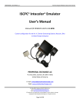
1
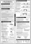
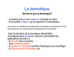
Integration Note
Manufacturer:
Ademco, First Alert
Model Number(s):
VISTA–128BP, VISTA–250BP, FA1660C
Core Module Versions:
3.0 or above
Comments:
Document Revision Date:
8/6/2013
OVERVIEW AND SUPPORTED FEATURES
The Ademco Vista 128BP, 250BP and the First Alert FA1660C are security panels that integrate with
the g! system using an RS-232 serial connection. The panel requires the model 4100 SM serial interface
module to enable the RS-232 communication between the g! system controller and the control panel.
Integration of the security system provides monitoring and control from any touch screen, telephone or
computer both locally and remotely. Additionally, events occurring in the security system can trigger
system commands in other sub-systems in the home. For example, a burglar alarm can turn all the lights
on and send out email alerts.
IMPORTANT! This document applies to the Ademco/First Alert 128/250BP/FA1660C panels, and does
not apply to the BPE panels. The 128BPE (and variants) are NOT SUPPORTED. In some cases it may
not be clear from hardware/packaging that the 128BP is in fact a 128BPE, as the difference is primarily
firmware. a 4.x firmware version is BPE, a 3.x or earlier firmware is BP. To tell if you have a BPE panel,
enter programming mode ([Installer Code] + [8000]) AND go to field *92; you will have two lines of info 087
2nd line -03 indicates V3.xx, if – 04 = V4 chip.
(If field 1*78 says not used and 3* is not there then it’s a V3.xx.)
******The BPE (4.x) firmware requires a different protocol and wiring and is not supported!******
THESE PANELS SUPPORT THE FOLLOWING FEATURES:
Arm – Disarm: Arm and disarm from the Viewer interface is supported for partition number 1 only. Status
information is available for all partitions.
Zone Status: Zone status information is available for all zones (in any partition), and is properly shown in
the Viewer. See exceptions below.
History View: The history view is properly supported on any Viewer.
Auto Zone and Partition Detection: After a zone has been faulted the g! system will automatically
detect the zone number, partition number and zone name.
THESE PANELS DO NOT SUPPORT THE FOLLOWING FEATURES:
Zone Bypass: Zones cannot be bypassed from the g! interface, only from the Ademco or First Alert
keypads. In the Ademco panel zones can be configured to automatically bypass if they are faulted when
arming the panel. Using this feature works well to overcome this limitation.
Multiple Partition Arm / Disarm: Only partition number 1 can be armed or disarmed from the g! user
interface, due to a limitation in the Ademco protocol and panel.
Auto Arm: Arming as a System Command from the Event Mapper is not supported with this panel.
ELAN Home Systems ● 1690 Corporate Circle ● Petaluma, CA 94954 USA
tech support: 800.622.3526 • main: 760.710.0990 • sales: 877.289.3526 • email: [email protected]
©2013 ELAN Home Systems. All rights reserved. ELAN and g! are trademarks of ELAN Home Systems. All other trademarks are the property of their respective owners.
Zone Status: Zone status information for entry and exit zones is not communicated to g! during entry
and exit delays.
Entry/Exit Delay: This panel will not notify g! that it is in entry or exit delay, as a result entry/exit delay as
a System Trigger or Condition and Announce Security Events is not supported with this panel.
Multiple Access Codes: Only one access code can be used to arm and disarm the panel from the g!
interface.
Relays: The relays on the panel can not be controlled from the g! interface or the g! Event Mapper.
Panic Button: The g! interface can not send a panic command to the Ademco panel.
Any feature not specifically noted as supported should be assumed to be unsupported.
INSTALLATION OVERVIEW
1. Install the security system and program the panel for the RS-232 interface. Use zone 9 (terminal
23) for RS-232 communication, as indicated by the Ademco documentation. When connecting a
g! system to an Ademco / First Alert panel, do not wire a zone sensor to zone 9 (terminal 23).
Zone 9 is only used for RS-232 communications.
2. Run a Cat5 wire from the g! system to the security panel and test the cable.
3. Test the security panel, zone sensors and keypads for functionality.
4. Connect the g! system to the panel electrically. This step requires a DB-25 Male to DB-9 Female
adapter that is not included in the Ademco / First Alert connector kit. Use a Belkin F2L088 or
equivalent.
5. On the security tab in the configurator add a communication device and security panel and
confirm communication between the panel and the g! system controller. See g! Configuration
Details below.
6. Fault all the zones in the system. Faulting the zone sends a message to the g! system which
then automatically adds the zone in the Configurator. Zones that can’t be easily faulted must be
added by hand. Confirm that all zones are visible in the Configurator and properly associated
with their partition. Optionally change the names for each zone and partition with the
Configurator.
7. Enter the User # for the access code that will be used from the g! interface in the configurator
under partition 1. See Note 1 in g! Configuration Details section below.
8. Test the arming and disarming capability from a computer or touch screen and confirm history
function.
2 of 6
CONNECTION METHODS
BILL OF MATERIALS
#
D ev ic e
M anuf a ct urer
P art N um be r
P ro t o c o l
C o nne ct o r T ype
1
Control Panel
Ademco /First Alert
128BP,250BP,FA1660C RS-232
Vario us
2
Serial Interface M o dule
Ademco
4100SM
RS-232
DB-25 M ale x Terminal Strip
3
DB25M X DB 9F Adapter Belkin
F2L088
RS-232
DB-25 M ale X DB-9 Female
4
DB9M to RJ45 Adapter
HA -CB-307
RS-232
DB-9 M ale X RJ-45 Female
5
Cat5 Cable
Installer
N/A
RS-232
RJ-45 M ale X RJ-45 M ale
6
g! Co ntro ller
Elan
Various (ex. HC-12)
RS-232
Rj-45 Female
Elan
DIAGRAM 1: SECURITY PANEL TO SERIAL INTERFACE CONNECTION DETAILS
The following diagram shows how to wire the 4100SM to the panel.
3 of 6
N o tes
Not included with 4100SM
M ust terminate all 8 co nductors
PANEL PROGRAMMING
Before communication can start between the g! system and the Ademco or First Alert panels there are
several fields that need to be changed in the panel configuration. You will need the installer access code
to enter the programming mode. The default code is 4140 for new installations.
To enter programming mode press the installer code and then [8000]. Once in programming mode,
changing the value of a field can be accomplished by pressing [*] + [Field #] + [ Value ]. The keypad will
ding 3 times and advance to the next field after the value had been entered. For example: Programming
field 70 to a value of 11111 requires the following key strokes [*] + [70] + [1] + [1] + [1] + [1] + [1]. To exit
the programming mode, press [*] + [99]. If you cannot gain entry to the programming menu using the
installer code then this method of access may be locked out on the device. The only way to access the
unit in that case is by pressing [*] and [#] simultaneously within 30 seconds of the device powering up.
The panel will need to be disconnected from power and the backup battery to create this condition.
Step
Instructions
Comments
1
Press [Installer Code] + [8000]
Enter programming mode on page (0)
2
Press [*] + [05] + [1]
Sets field *05 to 1 and enables System Events Notify
3
Press [*] + [14] + [1]
Sets field *14 to 1 and enables RS-232 Input
4
Press [*] + [94]
Changes to the next page(1)
5
Press [*] + [70] + [1]+[1]+[1]+[1] +[1]
Sets field 1*70 to 11111 and enables Event log types
Alarm, Check, Bypass, Open/Close and System
6
Press [*] + [72] + [1]
Sets field 1*72 to 1 and enables the Event Log
Printer On- Line Printer
7
Press [*] + [73] + [0]
Sets field 1*73 to and enables a Baud Rate of 1200
8
Press [*] + [94]
Changes to the next page (2)
9
Press [*] + [30] + [0]
Sets field 2*30 to disable Pager
10
Press [*] + [99]
To change to previous page (1)
11
Press [*] + [99]
To change to previous page (0)
12
Press [*] + [99]
To exit programming mode
4 of 6
g! CONFIGURATION DETAILS
The following table provides settings used in the g! Configurator when connecting to the Ademco / First Alert panel. Please refer to the Configurator Reference
Guide for more details.
o
“<Select>”
Select the appropriate item from the list (or drop-down) in the Configurator.
o
“<User Defined>”, etc.
Type in the desired name for the item.
o
“<Auto Detect>”, etc.
The system will auto detect this variable.
o
“<Defined in Security System>”
Devices
The security installer must provide the information to you.
Variable Name
Setting
Name
Type
Communication Type
Location
Com Port
<User Defined> (Default: Security)
Serial Port
Standard Connection
<User Defined> (Not Required)
<Select>
Name
Device Type
Location
Comm Device
Settings
<User Defined> (Default: Ademco VISTA-128BP,250BP,FA1660C)
Ademco VISTA-128BP,250BP,FA1660C
<User Defined> (Not Required)
<Select> (Default: Secuirty)
<Select>
Disarm
Mode 1
Mode 2
Name
Disarm
Stay
Away
Partions
Name
User Number
Show Partition
Areas in Partition
<User Defined>
<Defined in Security System> (See Note 1)
Yes
<User Defined> (Not Required)
Zones
Name
Enable Bypass
Exists in Partition
<User Defined>
No (See Note 2)
<Select> (See Note 3)
Communication Devices
Security Panels
Show
Yes
Yes
Yes
Auto
NO
NO
NO
Comments
Choose HEX for BP panels.
Keys
4
4
4
Notes:
1. Only partition number 1 can be armed or disarmed from the g! interface. Ask the security installer for the User Number in partition number 1 that corresponds to your Pass Code.
Alternatively, go to a security keypad in the partition and enter your Pass Code +[*]+[*} to display the User Number that matches that Pass Code.
2. Ademco does not support bypassable zones from external automation systems.
3. For each zone, add the partitions in which that zone is a part.
5 of 6
COMMON MISTAKES
1. Failing to test the Cat5 cable assembly. It is easy to make a mistake when terminating the Cat5
cable with the RJ-45 connectors. Always use a LAN tester to check for continuity and shorts.
2. Using a Cat5 patch cable without all 8 conductors. Some Ethernet patch cables only have the 4
conductors (1,2,3,6) needed for Ethernet communications. These cables will not work as patch
cables for RS-232 communications. Visually inspect the clear plastic connectors to determine if
all 8 wires are present.
3. Connecting a zone to terminal 23 on the security panel. Terminal 23 (zone 9) is used for RS-232
communications, and therefore cannot be used for any type of input or zone.
4. Using the wrong User Number for partition number 1. Arming or disarming partition number 1
requires the correct User Number for your Pass Code in partition number 1. To retrieve the User
Number for your Pass Code in partition number 1, go to a keypad in partition number 1 and enter
your Pass Code +[*]+[*]: this will display the User Number on the keypad.
5. Using a null modem to connect the RS-232 port. The Ademco / First Alert serial connections do
not require a null modem when connecting to a g! Controller or SerialBrick. The 4100SM kit has
many type of serial adapters, use only the ones specified above.
6. Using the incorrect ELAN DB-9 to RJ-45 adapter to connect to the security panel hardware. At
the panel, use the HA-CB-307.
7. Failing to plug the Cat5 cable assembly into the correct port. Make sure the RJ-45 connector is
plugged into the same port (COM1, 2, 3 etc.) that is specified in the Configurator.
8. Using a 4.x firmware (BPE) panel. These are not supported. See Page 1 for details.
9. Incorrect Settings for zone numbering. If duplicate zones/wrong zone numbers are autopopulating in the system, check the Security Panel Settings field. (6.2 and newer builds only)
6 of 6