1
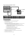
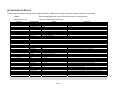
Integration Note
Manufacturer:
Marantz
Model Number(s):
SR6006, SR5006
Core Module Version:
5.4 or newer required
Document Revision Date:
1/15/2013
OVERVIEW AND SUPPORTED FEATURES
Marantz receivers include an RS-232 or Ethernet connection which is used to connect to the g! system
and provide full two-way communications, enabling reliable control as well as providing feedback to g!
when changes (such as the current source or volume levels) occur at the receiver.
MARANTZ RECEIVERS SUPPORT THE FOLLOWING FEATURES:
Basic Source and Volume Control: Select any available source and control volume with two-way
feedback. Changes made at the receiver (turning the volume control, changing source) are immediately
reflected in g!.
Multiple zones: Some Marantz receivers have a second and third zone, which can be controlled
independently from the Main Zone from g!. Note: The Marantz receivers may not support all sources in
the secondary zones. If these zones are used in the viewer then any unsupported sources will need to
be manually hidden using the zone source configuration page in the configurator so they are not visible
on the g! UI.
Onboard Tuner: The HD AM/FM tuner can be controlled from the standard AM/FM tuner interface.
RDS: RDS, or Radio Data System meta-data from HD Radio is read and displayed in the Viewer using
the built-in Tuner interface (supported models).
Listening Modes: Control of Listening Modes such as DTS, Pro-Logic etc. is available through settings
pages or custom controls.
Limited Support of iPod Dock + NET/USB Music: Support for iPod, digital music over IP/USB, and
internet radio features are available through event mapper commands, custom interface and navigation of
the Marantz on screen display ONLY. No pre-made interfaces are available and feedback may be limited
or non-existent.
MARANTZ RECEIVERS DO NOT SUPPORT THE FOLLOWING FEATURES:
Integration of iPod Dock (M-XPORT) and NET/USB Sources: Digital audio source control is limited to
source selection and volume control in g!. Note: xx06 models have commands to do basic one-way
cursor control on the Marantz OSD through a custom interface.
Additional Features: Many units include additional features such as trigger outs, IR and so forth. Unless
specifically listed above, g! does not integrate with these features.
Any feature not specifically noted as supported should be assumed to be unsupported.
ELAN Home Systems ● 1690 Corporate Circle ● Petaluma, CA 94954 USA
tech support: 800.622.3526 • main: 760.710.0990 • sales: 877.289.3526 • email: [email protected]
©2013 ELAN Home Systems. All rights reserved. ELAN and g! are trademarks of ELAN Home Systems. All other trademarks are the property of their respective owners.
INSTALLATION OVERVIEW
1. During the rough-in phase install the necessary speaker and video cabling for the theater installation.
2. Also during the rough-in phase, run a Cat5 wire from the location of the receiver back to the Network
Assembly of the g! system to provide the serial connection needed to control the receiver.
3. Install the speakers, display and other theater components.
4. Program the receiver according to the manufacturer’s documentation.
5. Test the receiver to ensure that the sources play correctly and that the audio and video operate as
expected.
6. Connect the g! system to the receiver electrically. RS-232: See the RS-232 connection diagram and
bill of materials for more information. Refer to the RS-232 Connection Options Integration Note for
other serial connection options. Ethernet: See the Ethernet connection diagram and bill of materials
for more information.
7. Configure the g! system for the receiver and confirm communication between the receiver and the g!
system controller.
8. Test the system by changing sources and volume to confirm the correct source plays.
CONNECTION DIAGRAM: SERIAL CONTROL
BILL OF MATERIALS
#
D ev ice
M anuf a c t ure r
P art N umber
P ro t o c o l
C o nnec t o r T ype
1
Cat5 Cable A ssy.
Installer
N/A
RS-232
RJ-45 M ale X RJ-45 M ale
2
DB 9F to RJ45 Adapter
Elan
HA -CB-307
RS-232
DB -9 M ale X RJ-45 Female
3
HC Co ntroller
Elan
Vario us
RS-232
RJ45 Female
2 of 5
N o t es
M ust terminate all 8 co nductors
CONNECTION DIAGRAM: ETHERNET CONTROL
BILL OF MATERIALS
#
D ev ice
1
Cat5 Cable A ssy.
2
3
M anuf a c t ure r
P art N umber
P ro t o c o l
C o nnec t o r T ype
N o t es
Installer
N/A
RS-232
RJ-45 M ale X RJ-45 M ale
M ust terminate all 8 co nductors
Network A ssembly
Elan
HW-NA -18X4
RS-232
RJ-45 Female
o r Router/Switch
HC Co ntroller
Elan
Vario us
RS-232
RJ45 Female
MARANTZ SETUP NOTES (ETHERNET):
1. Enter Menu and use the arrows to scroll and select “Manual Setup”.
2. Enter “Network Setup”.
3. Enter “Network Connecting”, select “Detail” and press <Enter>.
4. Use the arrows to set DHCP to “OFF”.
5. Use the arrows to configure the following settings, use arrows to select the desired field, <enter>
to edit, edit field using arrows, then <enter> again to save that field:
a. IP Address: 192.168.000.050 (change as needed for your network range; Elan
recommends setting the 1st AV receiver to x.x.x.50, the second to x.x.x.51, and so on)
b. Subnet Mask (Typical): 255.255.255.000
c.
Default Gateway (Router IP-Default): 192.168.000.001
d. Primary DNS (Router IP-Default: 192.168.000.001
e. Secondary DNS (typically not needed, may leave 000.000.000.000)
6. Use the arrows to scroll down to Exit to save settings.
7. Press <Return> to move back to the “Network Setup” menu, and then enter “Other”.
8. Configure Network Standby to ON.
9. Press <Return> a few times to exit the menu.
3 of 5
g! CONFIGURATION DETAILS
The following table provides settings used in the g! Configurator. Please refer to the g! Configurator Reference Guide for more details.
o
“<Select>”
Select the appropriate item from the list (or drop-down) in the Configurator.
o
“<User Defined>”, etc.
Type in the desired name for the item.
Devices
Variable Name
Setting
Comments
Name
Type
Communication Type
Location
COM Port
<User Defined> (Default: New Device)
Serial Port
Marantz
<User Defined> (Not Required)
<Select>
HomeLogic recommends renaming this for clarity.
Audio Tuners (Optional)
Name
Device Type
Location
COM Device
<User Defined> (Default: Marantz SR AM/FM Tuner)
Marantz SR BAND Tuner
<User Defined> (Not Required)
<Select> (Default: Receiver)
Optional: Only needed if the tuner will be a visible source in the Viewer interface
BAND = AM/FM, XM or Sirius as desired.
<Other RS-232 Sources>
Add any other RS-232 controlled sources. Refer to the Integration Note for each specific source device.
Communication Devices
<Other IR Controlled Sources>
<Video Display>
Other Audio Devices / Interfaces
Audio Zone Controllers
Sources
Zones
Tab Layout
See Note 1
Add IR devices on the Input/Output tab for other IR controlled sources. Refer to the Configurator Reference Guide .
Add the Video Display for the receiver. Refer to the Integration Note for the specific display, or the Generic Video Display Integration Note for an IR controlled display.
Name
Template
Default Device
<User Defined>
<Select>
<Select>
Add one Interface for each source that should appear in the Viewer
Name
Device Type
Location
COM Device
<User Defined>
<Select>
<User Defined> (Not Required)
<Select> (Default: Receiver)
Name
Source Device
Show Source
Source Icon
Display Name
<User Defined>
<Select>
<Select>
<Select>
<User Defined>
Sources must be previously configured in order to allow selection.
Set to No for any inputs on the receiver that are not used
This icon appears on the source button in the Viewer Interface
This text appears on the source button in the Viewer Interface
Name
Display
Universal Receiver
<Source>
Display On/Off
Display Source
<User Defined>
<Select>
<Select>
Select the Video Display in this zone
Refer to the g! Training Guide for more details
<Select>
<Select>
For each source, select what the display should do when that source is active
If using more than one input on the video display select the input for each source.
Interface Tabs
<Select>
Move any unused zones to the right into Available Zones to remove from the viewer
Select the RS-232 or IR controlled source for this interface
Defaults to make and model of receiver
Select your model of receiver
Notes:
Note 1: These models use the "Marantz" communication type, not "Marantz (D-Type)". If only one option available ("Marantz"), this is the correct type.
4 of 5
COMMON MISTAKES
1. Setting Marantz receivers into Economy Power mode. In Economy mode the unit will disable RS232 when it is in standby and cannot be turned on via serial commands. Check
Setup>Preferences>Standby and set to NORMAL. If set incorrectly, you will not be able to turn
unit ON from an OFF state.
2. Using the wrong Communication Type. The receiver models listed in the document all use the
Marantz (D-Type) protocol. (Note: On older versions of software, there is only one
Communication Type, “Marantz”. If only one “Marantz” communication type is present, a software
update is required to control this receiver.)
5 of 5