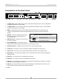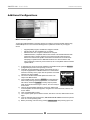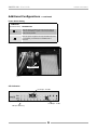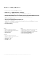
1
2-channel
24 bit, 192 kHz, AD/DA Converter
User’s Guide
v1.0 - October 2004
2-channel
24 bit, 192 kHz, AD/DA Converter
User’s Guide
v1.0 - October 2004
ROSETTA 200 – User’s Guide
APOGEE ELECTRONICS
Warnings & Copyrights
FCC warning
This equipment has been tested and found to comply with the limits for a Class A digital device, pursuant to Part 15 of the FCC rules. These limits are designed to provide reasonable protection against
harmful interference when operated in a commercial environment. This equipment generates, uses,
and can radiate radio frequency energy and, if not installed and used in accordance with the instruction manual, may cause harmful interference to radio communications. Operation of this equipment in
a residential area is likely to cause harmful interference, in which case the user will be required to take
whatever measures necessary to correct the interference at his own expense.
Copyright Notice
The Apogee ROSETTA 200 is a computer-based device, and as such contains and uses software in
ROMs. This software, and all related documentation, including this User’s Guide contain proprietary
information which is protected by copyright laws. All rights are reserved. No part of the software and its
related documentation may be copied, transferred, or modified. You may not modify, adapt, translate,
lease, distribute, resell for profit or create derivative works based on the software and its related documentation or any part thereof without prior written consent from Apogee Electronics Corporation, U.S.A.
Software Notice
Redistribution and use in source and binary forms, with or without modification, are permitted provided
that the following conditions are met:
• Redistributions of source code must retain the above copyright notice, this list of conditions and the
following disclaimer.
• Redistributions in binary form must reproduce the above copyright notice, this list of conditions and
the following disclaimer in the documentation and/or other materials provided with the distribution.
THIS SOFTWARE IS PROVIDED BY THE COPYRIGHT HOLDERS AND CONTRIBUTORS “AS IS” AND ANY EXPRESS OR IMPLIED WARRANTIES, INCLUDING, BUT NOT LIMITED TO, THE IMPLIED WARRANTIES OF MERCHANTABILITY AND FITNESS FOR A PARTICULAR
PURPOSE ARE DISCLAIMED. IN NO EVENT SHALL THE COPYRIGHT OWNER OR CONTRIBUTORS BE LIABLE FOR ANY DIRECT, INDIRECT, INCIDENTAL, SPECIAL, EXEMPLARY, OR CONSEQUENTIAL DAMAGES (INCLUDING, BUT NOT LIMITED TO, PROCUREMENT OF
SUBSTITUTE GOODS OR SERVICES; LOSS OF USE, DATA, OR PROFITS; OR BUSINESS INTERRUPTION) HOWEVER CAUSED AND ON
ANY THEORY OF LIABILITY, WHETHER IN CONTRACT, STRICT LIABILITY, OR TORT (INCLUDING NEGLIGENCE OR OTHERWISE) ARISING
IN ANY WAY OUT OF THE USE OF THIS SOFTWARE, EVEN IF ADVISED OF THE POSSIBILITY OF SUCH DAMAGE.
© Copyright 2004, Apogee Electronics Corporation. All rights reserved.
ii
ROSETTA 200 – User’s Guide
APOGEE ELECTRONICS
Registration and Warranty Information
Be sure to register your ROSETTA 200, either by filling in the enclosed Registration Card or by
completing the on-line registration form at our Web site: http://www.apogeedigital.com/support/. If
you do so, Apogee can contact you with any update information. As enhancements and upgrades are
developed, you will be contacted at the registration address. Firmware updates are free for the first
year of ownership unless otherwise stated. Please address any inquiries to your dealer or directly to
Apogee at:
APOGEE ELECTRONICS CORPORATION,
3145 Donald Douglas Loop South, Santa Monica, CA 90405, USA.
TEL: (310) 915-1000, FAX: (310) 391-6262
Email: [email protected]. Web: http://www.apogeedigital.com/
APOGEE ELECTRONICS CORPORATION warrants this product to be free of defects in material and
manufacture under normal use for a period of 12 months. The term of this warranty begins on the
date of sale to the purchaser. Units returned for warranty repair to Apogee or an authorized Apogee
warranty repair facility will be repaired or replaced at the manufacturer’s option, free of charge.
ALL UNITS RETURNED TO APOGEE OR AN AUTHORIZED APOGEE REPAIR FACILITY MUST
BE PREPAID, INSURED AND PROPERLY PACKAGED, PREFERABLY IN THEIR ORIGINAL BOX.
Apogee reserves the right to change or improve design at any time without prior notification. Design
changes are not implemented retroactively, and the incorporation of design changes into future units
does not imply the availability of an upgrade to existing units.
This warranty is void if Apogee determines, in its sole business judgment, the defect to be the result
of abuse, neglect, alteration or attempted repair by unauthorized personnel.
The warranties set forth above are in lieu of all other warranties, expressed or implied, and Apogee
specifically disclaims any and all implied warranty of merchantability or of fitness for a particular
purpose. The buyer acknowledges and agrees that in no event shall the company be held liable for
any special, indirect, incidental or consequential damages, or for injury, loss or damage sustained by
any person or property, that may result from this product failing to operate correctly at any time.
USA: Some states do not allow for the exclusion or limitation of implied warranties or liability for
incidental or consequential damage, so the above exclusion may not apply to you. This warranty
gives you specific legal rights, and you may have other rights which vary from state to state.
Service Information
The ROSETTA 200 contains no user-serviceable components: refer to qualified service personnel for
repair or upgrade. Your warranty will be voided if you tamper with the internal components. If you
have any questions with regard to the above, please contact Apogee.
In the event your ROSETTA 200 needs to be upgraded or repaired, it is necessary to contact Apogee
prior to shipping, and a Return Materials Authorization (RMA) number will be assigned. This number
will serve as a reference for you and helps facilitate and expedite the return process. Apogee requires
that shipments be pre-paid and insured — unless otherwise authorized in advance.
IMPORTANT: ANY SHIPMENT THAT IS NOT PRE-PAID OR IS SENT WITHOUT AN RMA
NUMBER WILL NOT BE ACCEPTED.
iii
ROSETTA 200 – User’s Guide
APOGEE ELECTRONICS
Declarations of Conformity
Declaration of Conformity—FCC
Apogee ROSETTA 200
This device complies with Part 15 of the FCC Rules. Operation is subject to the following two conditions:
(1) This device may not cause harmful interference
(2) This device must accept any interference received, including interference that may cause undesired operation.
This equipment has been tested and found to comply with the limits of a Class B digital device, pursuant to Part
15 of the FCC Rules. These limits are designed to provide reasonable protection against harmful inteference in a
residential installation. This equipment generates, uses and can radiate radio frequency energy and, if not installed
and used in accordance with the instructions, may cause harmful interference to radio communications. If this
equipment does cause harmful interference to radio or television reception, which can be determined by turning
the equipment off and on, the user is encouraged to try to correct the interference by one or more of the following
measures:
1. Re-orient or relocate the receiving antenna.
2. Increase the separation between the equipment and receiver.
3. Connect the equipment into an outlet on a different circuit from that to which the receiver is connected.
4. Consult the dealer or an experienced radio/TV technician for help.
NOTE: The use of non-shielded cable with this equipment is prohibited.
CAUTION: Changes or modifications not expressly approved by the manufacturer responsible for compliance
could void the user’s authority to operate the equipment.
Apogee Electronics Corporation, 3145 Donald Douglas Loop South, Santa Monica, CA 90405.
Betty Bennett, CEO.
Industry Canada Notice
This Class B digital apparatus meets all requirements of the Canadian Interference-Causing Equipment Regulations. Cet appareil numérique de la classe B respecte toutes les exigences du Règlement sur le matérial brouilleur
du Canada.
Declaration of Conformity – CE
Apogee Electronics Corporation hereby declares that the product, the ROSETTA 200, to which this declaration
relates, is in material conformity with the following standards or other normative documents:
• EN50081-1/EN55022; 1995
• EN50082-1/IEC 801-2, 3, 4; 1992
following the provisions of:
• 73/23/EEC – Low Voltage Directive
• 89/336/EEC – EMC Directive
Declaration of Conformity – Japan
Apogee Electronics Corporation hereby declares that the ROSETTA 200, to which this declaration relates, is in
material conformity with the VCCI Class A standard.
Declaration of Conformity – Australia
Apogee Electronics Corporation hereby declares that the ROSETTA 200 is in material conformity with AN/NZS
standard requirements.
iv
ROSETTA 200 – User’s Guide
APOGEE ELECTRONICS
OWNER’S RECORD
The serial number is located on the rear panel of the unit. We suggest you record the
serial number in the space provided below. Refer to it whenever you call an authorized
Apogee Electronics repair facility or the manufacturer. Please be sure to return your completed warranty card immediately!
ROSETTA 200 Serial No._________________________________________________
Purchase Date__________________________________________________________
Dealer_________________________________________________________________
Phone_________________________________________________________________
Address________________________________________________________________
CAUTION:
Any changes or modifications not expressly approved by APOGEE ELECTRONICS
CORPORATION could void your authority to operate this equipment under the FCC rules.
Please register this unit by filling in the included registration card, or registering online at
http://www.apogeedigital.com/support/register.php Please read this manual – if you call for
technical support, we’ll assume that you have. There will be a quiz.
v
User’s Guide
Table of Contents
Introduction ....................................................................................................................2
Signal Flow Diagram ....................................................................................................2
Getting Started Quickly ..............................................................................................3
Using this manual...................................................................................................3
Connecting Power .................................................................................................3
Reset .....................................................................................................................3
Quickstart ..............................................................................................................3
Navigating the Front Panel ....................................................................................4-7
About Secondary Parameters ................................................................................4
Power Switch .........................................................................................................4
SAMPLE RATE ......................................................................................................4
AES FMT................................................................................................................4
Optical Output Format ...........................................................................................4
SYNC .....................................................................................................................4
WC I/O ...................................................................................................................5
LOCK .....................................................................................................................5
SOURCE (to Digital Outputs) ................................................................................5
SRC........................................................................................................................5
CLEAR ...................................................................................................................5
SOFT LIMIT............................................................................................................5
CODA .....................................................................................................................5
PROCESS..............................................................................................................5
AUTO SRC ..............................................................................................5
24-BIT/16-BIT/UV22HR ...........................................................................5
Sample rate conversion..........................................................................................6
CALIBRATION .......................................................................................................6
APTOMIZER ..........................................................................................................7
ON-OFF ...................................................................................................7
TRIM ........................................................................................................7
LEARN .....................................................................................................7
METERS ................................................................................................................7
SOURCE (to Analog Outputs) ...............................................................................7
SRC........................................................................................................................7
Connections on the Rear panel ...............................................................................8
L-R ANALOG IN .....................................................................................................8
L-R ANALOG OUT .................................................................................................8
MIDI IN/OUT...........................................................................................................8
WORD CLOCK IN/OUT..........................................................................................8
WC IN TERMINATION ...........................................................................................8
OPTICAL IN/OUT...................................................................................................8
S/PDIF IN/OUT.......................................................................................................8
AES IN 1-2 .............................................................................................................8
AES OUT 1-2 .........................................................................................................8
AC IN .....................................................................................................................8
Additional Configurations ..........................................................................................9
MIDI Firmware Update ...........................................................................................9
Power Switch Setting ...........................................................................................10
A/D Calibration .....................................................................................................10
ROSETTA 200 – User’s Guide
APOGEE ELECTRONICS
Introduction
Apogee Electronics’ Rosetta 200 is a two channel Analog to Digital and Digital to Analog converter that
features the same premium quality signal path as its big brother - the Rosetta-800 - as well as enhanced
digital functionality that makes it suitable for a wide variety of applications in the modern digital studio.
The Rosetta 200 includes :
•
•
•
•
•
•
2 channels of premium 24-bit AD/DA conversion
Sample rates up to 192kHz with Apogee’s “Intelliclock”
2 channels of AES, S/PDIF (coax & optical), and ADAT/SMUX I/O
MIDI I/O (with optional X-FireWire card)
Optional FireWire expansion card for compatibility with OS X, and Windows XP (X-FireWire card)
Optional expansion card for direct connection to Pro Tools HD & Mix systems (X-HD card,
X-Digi-Mix card)
• “Soft Limit” for maximum digital level without overs
• “CODA”: The “APTOMIZER” Level Normalizer, Sample Rate Conversion (SRC), and
Apogee’s “UV22HR” for superior dither to 16-bit
• Full channel metering
Signal Flow Diagram
Source to Analog Outs button
To Analog Outputs
SRC
S/PDIF In
ADAT In
OPTION In
AES In
ANALOG In
SOFT LIMIT
APTOMIZER
A/D
To S/PDIF Out
To ADAT Out
Source to Digital Outs button
UV22HR
SRC
To OPTION Out
To AES Out
CODA
Represents CODA processing
Basic Signal Flow Diagram (without signal) shows Rosetta 200’s
ability to configure two independent signal paths.
Figure 1
2
ROSETTA 200 – User’s Guide
APOGEE ELECTRONICS
Getting Started Quickly
1
3
5
4
USING THIS MANUAL
In this manual, “parameters” are defined as the characteristics of operation, such as
CLOCK SOURCE or AES format, and are capitalized in this manner : CLOCK SOURCE.
“Values” are defined as the choices available for each parameter – for example, the parameter CLOCK SOURCE has
the values INTernal,WC and INPUT Values are italicized in this manner: S/PDIF.
“Settings” are defined as the entire set of parameters and values.
When physical controls such as buttons or switches are referred to in the text,
they are highlighted in this manner: DOWN.
CONNECTING POWER
The Rosetta 200 accepts an AC input of 90 to 264 volts AC at a frequency of 47 to 440 hz. Thus, the unit may be
connected to virtually any AC power outlet found worldwide without concern for voltage settings or fuse ratings.
RESET
To reset the Rosetta 200, power up the unit while holding down the SAMPLE RATE button. This provides a quick
method to return to factory default settings (including CAL levels).
QUICKSTART
To quickly get started using the Rosetta 200, please follow these steps:
1)
2)
3)
4)
5)
Connect the AC input and press the POWER button.
On the rear panel, connect an analog signal source to the Analog Inputs, connect a digital device to the
appropriate digital I/O (ADAT is used in this example), and connect the Analog Outputs to a monitoring
system.
Set SAMPLE RATE to 44.1.
Set the SOURCE (to Digital Outputs) to Analog.
Set the SOURCE (to Analog Outputs) to ADAT.
3
ROSETTA 200 – User’s Guide
APOGEE ELECTRONICS
Navigating the Front Panel
1
2
3 4
5
About Secondary Parameters - Most front panel buttons control both a primary and secondary parameter; as
indicated by the two labels under each button. Secondary parameters are usually accessed by pressing and
holding the corresponding button.
1)
Power Switch – The POWER Switch may be configured to operate in two distinct modes : 1) the unit
powers up immediately when power is applied to the AC input (for example, when the unit is installed in a
rack with a Master power switch); 2) the POWER switch must be pressed to turn the unit on. See page 10
for POWER switch configuration details.
The LED adjacent to the POWER switch indicates that the unit is receiving a proper AC input, and is in
Standby mode. The LED extinguishes when the unit is powered on.
2)
SAMPLE RATE - This parameter determines the sample rate of the unit, either by selecting an internally
clocked rate between 44.1kHz and 192kHz or by locking to an EXTernal clock source as selected by the
SYNC parameter. When EXT is selected, the 44.1-192 LEDs display the sample rate of the external source.
3)
AES FMT (AES Format)– At sample rates between 88.2 and 192 kHz, the Rosetta 200’s AES I/O may be
configured for either Single or Double wire operation.
To determine the current AES format, press and hold SAMPLE RATE; Double wire format is indicated by the
illumination of the 3 DW LEDs above the SYNC and SOURCE buttons.
To change the AES format, first press and hold SAMPLE RATE and then press SYNC to toggle DW on or off.
When clocking to the AES input, the AES format is determined by the format of the SYNC value selected
(either AES or AES + DW).
4)
Optical Output Format – At sample rates between 44.1 and 96 kHz, the Optical Output format may be set
to either ADAT (S/MUX) or S/PDIF.
To determine the current Optical Output format, press and hold SAMPLE RATE; the format is indicated by
the optical format LED lit above the SYNC and SOURCE buttons.
To change the Optical format, first press and hold SAMPLE RATE and then press SOURCE (to Digital
Outputs) to toggle between ADAT (S/MUX) and S/P OPT.
By selecting one Optical format as a SOURCE (to Digital Outputs) and setting Optical Output to the other
format, it’s possible to convert between ADAT (S/MUX) and S/PDIF Optical formats.
5)
SYNC – When SAMPLE RATE is set to EXT, the SYNC parameter determines the unit’s clock source.
S/P COAX – clock is derived from the S/PDIF In coaxial connector
S/P OPT – clock is derived from the Optical In connector; the input signal is assumed to be S/PDIF format.
ADAT – clock is derived from the Optical In connector; the input signal is assumed to be ADAT format, thus
the resultant sample rate will be in the 44.1-48kHz range.
ADAT + S/MUX – clock is derived from the Optical In connector; the input signal is assumed to be S/MUX
format, thus the resultant sample rate will be in the 88.2-96kHz range.
OPTION – clock is derived from the connected option card input (e.g. X-FireWire)
AES – clock is derived from the AES In 1 connector.
AES + DW – clock is derived from the AES 1 In connector; the input signal is assumed to be Double wide
format, thus the resultant sample rate will be in the 88.2-192kHz range.
WC – clock is derived from the Word Clock In connector.
4
ROSETTA 200 – User’s Guide
APOGEE ELECTRONICS
Navigating the Front Panel -
continued
12
7
6
8
9
10
11
13
6)
WC I/O (Word Clock I/O Ratio) – This parameter determines the ratio between the Word Clock Input/Output
frequency and the unit’s sample rate.
•To set the ratio between a Word Clock Input and the unit sample rate (when locked to WC):
1 Connect a word clock signal to the Word Clock In, set SAMPLE RATE to EXT, and set SYNC to WC.
Verify that both the Wide and Narrow Lock LEDs light.
2 While holding down the SYNC button, press the SAMPLE RATE button to toggle to the desired sample
rate range.
• To set the ratio between the Word Clock Output frequency and the unit’s sample rate (when locked to all
other internal or external clock sources).
1 Select the desired sample rate or external clock source.
2 While holding down the SYNC button, press the SAMPLE RATE button to toggle to the desired word
clock output frequency range.
7)
LOCK – These LEDs indicate the Lock status of the Rosetta 200’s clock. Two levels of lock precision are
displayed, Wide and Narrow. When both Wide and Narrow are lit, the Rosetta 200 has locked to the selected
CLOCK SOURCE in such a way as to ensure the highest quality conversion. If only the Wide LED lights, the
stability of the clock source is questionable, and the source should be verified.
8)
SOURCE (to Digital Outputs) – This parameter selects the input source that is routed to ALL digital
outputs. To employ the Rosetta 200’s A/D converters, set this parameter to Analog.
9)
SRC (Sample Rate Conversion) – When a digital source has been selected, press and hold SOURCE (to
Digital Outputs) to engage SRC. Please see AUTO SRC (below) for more detailed information..
10) CLEAR - This button clears the meter’s OUCH (OVER) LEDs
11) SOFT LIMIT – Press and hold CLEAR to engage SOFT LIMIT on both analog inputs. Soft Limit is an
analog process that rounds transient peaks –4 dBFs and above with attack and release times that may be
considered instantaneous. As with any peak reduction device working at such fast time constants, Soft Limit
is most effective with signals whose peak information is greater than its average (or RMS) information, such
as drums, plucked instruments and dynamic mixes. Soft Limit may not be the appropriate choice for limiting
signals whose crest factor (peak to RMS ratio) is low, such as bass or organ.
12) CODA – The CODA Audio Finishing Module is comprised of three processes : SRC (Sample Rate
Conversion), UV22HR and APTOMIZER.
13) PROCESS – This parameter toggles AUTO SRC on and off and sets digital output resolution to 24 or 16bit/UV22HR
AUTO SRC (Sample Rate Conversion) – When AUTO SRC is engaged, sample rate conversion is
automatically applied to digital inputs when needed. If a selected digital input is detected to be nonsynchronous with the unit’s clock, sample rate conversion is automatically applied to the input and the
corresponding SRC LED lights.
24-BIT/16-BIT/UV22HR – When the unit sample rate is set to a range of 44.1-48k, the bit resolution of all
digital outputs may be set to either 24-Bit or 16-Bit/UV22HR. When 16-Bit/UV22HR is selected, Apogee’s
proprietary dither signal, UV22HR, is employed to encode 24-bit resolution in a 16-bit signal.
Please note: AUTO SRC will be available in a future software upgrade.
5
ROSETTA 200 – User’s Guide
Navigating the Front Panel -
APOGEE ELECTRONICS
continued
14
Sample Rate Conversion - As the number of digital audio sample rates increases, the necessity for high quality conversion
between these rates grows. For the first time on an Apogee product, sample rate conversion is offered on the Rosetta 200. To
employ sample rate conversion:
1 Connect the source to one of the Rosetta 200’s digital inputs and set SOURCE (to Digital Outputs) to the
appropriate setting.
2 Connect the destination to a Rosetta 200 digital output.
3 Select the desired output sample rate
4 Press and hold the SOURCE (to Digital Outputs) button until the SRC LED lights.
5 Keep in mind that SRC may be applied to one digital input only.
To get a better sense of SRC’s function, here are a few examples where it might be employed:
96k/24 bit to CD (44.1kHz 16 bit) – Perhaps the most common application of SRC is the conversion of high sample rate
audio to the Compact Disc rate of 44.1kHz. By using SRC in conjunction with Apogee’s UV22 bit resolution reduction
algorithm, CD transfers retain the quality and resolution of the original high sample rate/ bit depth audio. Follow these
steps to convert a 96k, 24 bit AES digital input to a 44.1kHz, 16 bit digital output.
1 Connect the 96kHz signal to AES Input 1, connect the appropriate digital output to the destination machine.
2 Set SAMPLE RATE to 44.1
3 Set SOURCE (to Digital Outputs) to AES; set SOURCE (to Analog Outputs) to AES to monitor the converted
signa via the analog outputs.
4 Press and Hold SOURCE (to Digital Outputs) and verify that the SRC LED next to each SOURCE button is lit
5 Press PROCESS to select 16 bit/UV22HR
6 The signal routed to all digital outputs is now 44.1kHz 16-bit.
Monitoring or transferring from non-synchronous digital sources quickly – To monitor or transfer from nonsynchronous digital sources such as DAT machines, CD players and synth modules with digital outputs, usually it’s
necessary to lock the entire digital system to that source, potentially degrading clock quality and often disrupting work flow.
When AUTO SRC is engaged, it’s possible to set either SOURCE path to a non-synchronous input without modifying the
Rosetta 200’s sample rate or clock source. For example, if the Rosetta 200 is the clock master of a digital system running at
96kHz, it’s possible to input signals from a 48kHz synth without clocking to that input or changing sample rate.
14) CALIBRATION – Press and hold the PROCESS button to engage CAL mode. The following buttons are
used to change parameters in CAL mode:
Once in CAL mode, press PROCESS to set the channel(s) to calibrate, as indicated by the blinking
“Ouch” LED. It’s possible to calibrate each channel individually or both A/D or D/A channels
simultaneously.
Press + (CLEAR) to raise the calibration level of the selected channel(s), press – (SOURCE to Digital
Outputs) to lower the calibration level.
In calibration mode, the LED meters display a “zoomed-in” range of digital levels between –20 and –10
dBFs, as shown in Figure 7 (pg 10); each column of LEDs now corresponds to a 1 dB change in level.
To aid in precise calibration, a single LED lights ONLY when the corresponding channel’s actual level
is within +/- .1dB of the specified level, otherwise adjacent LEDs light to show that the actual level is
between two specified levels. For example, if a tone connected to the analog inputs results in a digital
level of -16.4 dBFs, both the “-16” and “-17” LEDs will light. When the actual level is within plus or minus
.1 dB of for example, -12 dBFs, ONLY the “-12” LED will light. Please note that when the Rosetta 200 is
reset, it is calibrated to the default level of +4 dBu = -16 dBFs (+/- 0.2 dB).
6
ROSETTA 200 – User’s Guide
Navigating the Front Panel -
APOGEE ELECTRONICS
continued
16
15
17
18
Follow these steps to calibrate the Rosetta 200:
1 Before entering CAL mode, set both SOURCE (to Digital Outputs) and SOURCE (to Analog Outputs) to Analog.
2 Connect a 1 kHz tone at the desired analog reference level (usually +4 dBu) to both Analog inputs, and
connect an analog meter (voltmeter or analog VU meter) to the Analog outputs.
3 Engage CAL mode by pressing and holding PROCESS.
4 Select the A/D channel(s) to calibrate, and press the + (CLEAR) or – (SOURCE to Digital Outputs) buttons until the
desired digital reference level is displayed on the corresponding LED bargraph. When only one LED (per channel) is
lit, the A/D is calibrated to within +- .1 db of the specified level.
5 Select the D/A channel(s) to calibrate, and press the + (CLEAR) or – (SOURCE to Digital Inputs)
15) APTOMIZER – A new Apogee technology developed for the Rosetta 200, APTOMIZER sets A/D and D/A
calibration levels by detecting peak level information at the A/D converter and adjusting both analog inputs and
outputs for the optimal setting. Think of APTOMIZER as an alert assistant who constantly re-calibrates the unit
based on the input received (even if “alert assistant” is an oxymoron).
ON-OFF – turns APTOMIZER On or Off. Note that when APTOMIZER is turned Off, calibration levels return to
the last manually adjusted values.
TRIM – Once the Rosetta 200 has determined an optimal calibration level in LEARN mode, it’s possible to trim
this level using the – (SOURCE) and + (CLEAR) buttons. Each button push modifies calibration levels .1 dB.
LEARN – Press and hold the APTOMIZER button to engage LEARN mode. While in LEARN mode,
the A/D calibration level is dynamically adjusted so that the highest peak detected at the analog inputs
results in a digital level of -.5 dBFs. To preserve unity gain through the unit (i.e. what goes in is what
comes out), the D/A calibration level is adjusted simultaneously.
APTOMIZER and Soft Limit – When LEARN mode is engaged, the A/D calibration level drops to its
lowest gain value in order to comfortably accept input peaks up to +24 dBu. To avoid misdetection
of peaks, Soft Limit is disengaged when LEARN mode is engaged. If using Soft Limit, it’s suggested
to check calibration levels once LEARN mode is disengaged, and modify if necessary with the TRIM
buttons (– (SOURCE) and + (CLEAR)).
When engaging LEARN mode, please note that previously detected calibration values set by
APTOMIZER are lost.
16) METERS – These bargraphs display the digital level of both SOURCE selections. When the Rosetta 200 is
configured as an A/D – D/A (i.e SOURCE (to Digital Outputs) is set to Analog and SOURCE (to Analog
Outputs) is set to a digital source), the ANALOG bargraph displays the analog input after A/D conversion
while the DIGITAL bargraph displays the digital input before D/A conversion.
17) SOURCE (to Analog Outputs) – This parameter selects the input source that is routed to the Analog
outputs. When a digital input is selected, the Rosetta 200’s D/A converters are employed to convert the
selected input to digital.
18) SRC (Sample Rate Conversion) – When a digital source has been selected, press and hold SOURCE (to
Analog Outputs) to engage SRC.
7
ROSETTA 200 – User’s Guide
APOGEE ELECTRONICS
Connections on the Rear Panel
10
2
1
3
4
5
6
7
8
9
11
12
13
1)
L-R ANALOG IN – These female XLR connectors accept balanced analog line inputs, and are adjustable for
a maximum level between +2 and +26 dBu.
2)
L-R ANALOG OUT – These male XLR connectors provide balanced analog line outputs, and are adjustable
a maximum level between +2 and +26 dBu.
3)
MIDI IN - This 5-pin DIN connector is used to update the Rosetta 200’s firmware, as described on page
9. When an X-FireWire Option card has been installed, MIDI input is routed to a connected computer via
FireWire.
4)
MIDI OUT – When an X-FireWire card is installed,
this 5-pin DIN connector outputs MIDI from a
connected computer.
14
15
WORD CLOCK IN, Termination Switch
Terminated switch position
5)
WORD CLOCK IN – This BNC connector accepts a
TTL Logic clock signal.
6)
WC IN TERMINATION – This pushbutton switch
determines the termination status of the Word Clock In, as depicted in Figure 1.
7)
WORD CLOCK OUT – This BNC connector provides a TTL Logic clock signal output.
8)
OPTICAL IN – This Toslink connector accepts ADAT, S/MUX and S/PDIF format optical inputs.
9)
OPTICAL OUT - This Toslink connector provides ADAT, S/MUX and S/PDIF format optical outputs.
Unterminated switch position
10) OPTION SLOT – This slot accepts X-DigiMix, X-HD and X-FireWire Option cards, which provide additional
digital I/O formats.
11) S/PDIF IN – This coaxial connector accepts S/PDIF format inputs.
12) S/PDIF OUT - This coaxial connector provides S/PDIF format outputs.
13) AES IN 1-2 – These female XLR connectors accepts AES Single and Double Wire format input.; when AES
Single Wire format is employed, use AES IN 1.
14) AES OUT 1-2 - These female XLR connectors provide AES Single and Double Wire format output.; when
AES Single Wire format is employed, both outputs are identical.
15) AC IN
8
Figure 3
ROSETTA 200 – User’s Guide
APOGEE ELECTRONICS
Additional Configurations
Figure 4
MIDI Firmware Update
To allow the greatest flexibility in the field, Apogee now employs a firmware update method using
stardard Midi protocol. You’ll need the following items to update the firmware of your Apogee
device:
•
•
•
•
1)
2)
3)
4)
5)
6)
7)
8)
9)
ApogeeUpdater program, available from Apogee’s website
New firmware file, also available from our website
Macintosh OSX 10.2 or higher or Windows XP computer
USB Midi interface, compatible with OS used. Please note that Midi interfaces with
proprietary latency-reducing modes do not properly transmit System Exclusive
data such as this firmware update. Ensure that such modes are turned off before
attempting to update firmware. USB Midi Interfaces such as the Edirol PC-300,
where proprietary modes may not be turned off, are not compatible with this firmware
update method.
To determine the version of firmware installed in the ROSETTA 200, press the SOURCE
(to Digital Outputs) button while powering on the unit.
Install both the ApogeeUpdater and the new firmware file onto a
computer equipped with a USB Midi Interface. It’s assumed that
all drivers necessary for the proper test and operation of the Midi
MIDI updater
Interface have been installed.
Connect the ROSETTA 200’s Midi Update Connector to an
output of the Midi Interface.
On the ROSETTA 200, press the SOURCE (to Analog Outputs)
button while powering up the Apogee device; once the device
has booted, release the SOURCE (to Analog Outputs) button.
When the signal level LEDs begin to “dance”, the unit is ready to
Figure 5
receive data.
Open the ApogeeUpdater application, and click on OPEN FILE.
In the Navigation window which appears, navigate to the new firmware file, select it, and
click on OPEN.
Click on DOWNLOAD TO UNIT.
The complete update process takes 8 minutes; after about 1 minute, data transfer should
begin.
Once the download has reached 100%, wait for the unit to re-boot and the front panel to
return to a normal operating state.
Before proceeding, reset the unit by pressing SAMPLE RATE while powering up the unit.
9
ROSETTA 200 – User’s Guide
APOGEE ELECTRONICS
Additional Configurations -
continued
Power Switch Setting
JUMPER P3
DESCRIPTION
(as seen from front)
When AC power is applied to the input, the unit does not
power up immediately; to power on the unit,the POWER
button must be pressed.
When AC power is applied to the input, Rosetta 200 powers
on immediately; nevertheless, the POWER switch is
functional.
Figure 6
JUMPER P3
Figure 7
A/D Calibration
for example: -16.4 dBfs
Figure 7
-20 -19
-18
-17 -16
-15 -14
-13 -12
-11
-10
for example: -12 dBfs
dBfs (CAL mode only)
10
Features and Specifications
• 2 channels of premium 24-bit AD/DA conversion
• Sample rates up to 192kHz with Apogee’s “Intelliclock”
• 2 channels of AES, S/PDIF (coax & optical), and ADAT/SMUX I/O, MIDI I/O
• Optional FireWire expansion card for compatibility with OS X, and Windows XP (X-FireWire card)
• Optional expansion card for direct connection to Pro Tools HD & Mix systems
(X-HD card, X-Digi-Mix card)
• “Soft Limit” for maximum digital level without overs
• “CODA”: The “APTOMIZER” Level Normalizer, Sample Rate Conversion (SRC), and Apogee’s
“UV22HR” for superior dither to 16-bit
• Full channel metering
INPUTS:
• Analog In 1-2: Balanced, XLR connectors
• AES in: x 2, transformer balanced, XLR connectors
• S/ PDIF In: Toslink and Coax
• ADAT/SMUX In: Toslink
• WC In: BNC 75 ohm
SPECS:
• Sample rates: 44.1 - 48k, 88.2 - 96k, 176.4 - 192k (+/-10%);
• Frequency response: 10 - 20k (+/- 0.2 dB) at 44.1k
• Analog max levels: adjustable between +2 dBu and +26 dBu
• Dynamic range: 114 dB A weighted (AD + DA)
• THD+N: -105 dB (AD), -103 dB (DA)
• Power: 90-250 VAC, 50-60Hz, 45Watt
OUTPUTS:
• Analog Out 1-2: Balanced, XLR connector.
• AES Out: x 2, transformer balanced, XLR connector
• S/ PDIF Out: Toslink and Coax
• ADAT/SMUX Out: Toslink
• WC Out: BNC 75 ohm
Due to on-going development Apogee reserves the right to change all information and specifications without notice.
ROSETTA 200 USER’S GUIDE - v1.0 - SEPTEMBER 2004
Text conceived and delivered by: Roger Robindore
Graphics and product illustration by: Sean McArthur