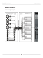
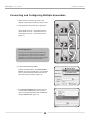
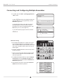
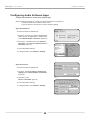
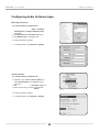
1
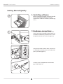
Multi-Channel,
24bit/192kHz Audio Interface
for the Macintosh
User’s Guide
v1.0 - June 2006
User’s Guide
Table of Contents
Owners Record ............................................................................................................. 2
Introduction ................................................................................................................... 3
Getting Started Quickly .......................................................................................... 4-7
1. Installing software ............................................................................................ 4
2. Hardware connections ....................................................................................... 4
3. OS X configuration ............................................................................................ 5
4. iTunes playback ................................................................................................. 5
5. DAW configuration ............................................................................................ 6
6. Recording .......................................................................................................... 7
General Operation................................................................................................... 8-11
Making Settings with Software Control Panels ...................................................... 8
Making Settings with Ensemble’s Front Panel Encoder Knobs ............................... 8
Setting Sample Rate .............................................................................................. 9
Using 176.4-192 kHz Sampling Rates ................................................................... 9
Setting Clock Source ............................................................................................. 9
Digital I/O ............................................................................................................. 9
Ensemble Routing .................................................................................................. 9
Input Routing Diagram ........................................................................................ 10
Output Routing Diagram ...................................................................................... 11
............................................ 12-13
Connecting and Configuring Multiple Ensembles
Advanced Clocking................................................................................................ 13
Maestro - Settings - Control Panel ................................................................. 14-15
Maestro - Settings - Output ............................................................................. 16-17
Maestro - Settings - Mic Pre ............................................................................ 16-17
Navigating the Front Panel .................................................................................... 18
Connections on the Rear Panel ............................................................................ 19
Connecting Your Studio .................................................................................... 20-21
Basic studio configuration ................................................................................... 20
5.1 surround configuration .................................................................................. 21
Configuring Audio Software Apps .................................................................. 22-23
Apple Soundtrack Pro .......................................................................................... 22
Apple Final Cut Pro .............................................................................................. 22
MOTU Digital Performer ...................................................................................... 23
Steinberg Nuendo ................................................................................................ 23
Troubleshooting .................................................................................................... 24-25
Warnings & Copyrights ............................................................................................ 26
Declarations of Conformity..................................................................................... 27
Registration and Warranty Information ........................................................... 28
Ensemble – User’s Guide
APOGEE ELECTRONICS
OWNER’S RECORD
The serial number is located on the rear panel of the unit. We suggest you record the serial number
in the space provided below. Refer to it whenever you call an authorized Apogee Electronics repair
facility or the manufacturer. Please be sure to return your completed warranty card immediately!
Ensemble Serial No._________________________________________________
Purchase Date__________________________________________________________
Dealer_________________________________________________________________
Phone_________________________________________________________________
Address________________________________________________________________
CAUTION:
Any changes or modifications not expressly approved by APOGEE ELECTRONICS
CORPORATION could void your authority to operate this equipment under the FCC rules.
Please register this unit by filling in the included registration card, or registering online at
http://www.apogeedigital.com/support/register.php Please read this manual – if you call for
technical support, we’ll assume that you have. There will be a quiz.
2
Ensemble – User’s Guide
APOGEE ELECTRONICS
Introduction
Ensemble is a digitally-controlled Firewire audio interface specifically designed for Apple Macintosh
computers. From mic preamps to Mac CoreAudio connectivity to headphone outputs, Ensemble includes all
that’s necessary for a high-quality Mac-based recording system.
Ensemble includes several of Apogee’s Core technologies, including:
SoftLimit
Soft Limit is an analog peak limiting circuit that instantaneously and gracefully controls transient peaks,
thereby allowing an additional 4 dB of headroom. Soft Limit may be engaged on all 8 Ensemble analog
inputs.
UV22HR
UV22HR is Apogee’s industry standard dither algorithm for reducing the word-length of a digital audio signal
from 24 to 16 bits. UV22HR is also being employed to produce dramatically improved internet and computer
audio content without increased file sizes or data rates.
Apogee Sample Rate Conversion (SRC)
Ensemble’s hardware sample rate conversion provides a high quality, flexible solution for working with digital
audio hardware and software running at different sample rates. Ensemble’s sample rate conversion may
be applied to a digital input (to convert an input stream to Ensemble’s sample rate) or to a digital output (to
provide an output stream at a user selected sample rate different than Ensemble’s rate).
Ensemble Requirements
1. Apple PowerMac 1.5GHz or higher, 512MB of RAM required, 1GB recommended
2. OS X 10.4.6
3. Apple Logic Pro 7.2.1
4. One Firewire 400 cable (per Ensemble)
3
Ensemble – User’s Guide
APOGEE ELECTRONICS
Getting Started Quickly
1. Installing software
Before connecting Ensemble, insert the included
CD into your Mac and follow the onscreen
instructions to install the necessary software (figure 1).
figure 1
2. Hardware connections
Connect Ensemble’s AC input to an AC outlet
of 90 to 250 volts; Ensemble’s power switch will
illuminate to indicate the presence of AC. Press
the power switch to turn the unit on (figure 2).
figure 2
Using the enclosed FireWire cable, connect one
of Ensemble’s FireWire ports to a FireWire 400
port on your Mac (figure 3).
figure 3
Connect a pair of headphones to Ensemble’s
1 output (figure 4).
figure 4
4
Ensemble – User’s Guide
APOGEE ELECTRONICS
Getting Started Quickly
3. OS X configuration
From your Mac’s Apple menu bar, open the
System Preferences window, then click on the
sound icon (figure 5).
figure 5
In the Sound Preferences window click on the
Output tab and select Ensemble (figure 6).
figure 6
4. iTunes playback
Open iTunes, select an audio file and initiate
playback (figure 7).
figure 7
Press the OUTPUT encoder knob until the
LED is lit and adjust the level in your headphones (figure 8).
1
figure 8
5
Ensemble – User’s Guide
APOGEE ELECTRONICS
Getting Started Quickly
5. DAW configuration
Configure your CoreAudio compatible software
to communicate with Ensemble hardware I/O.
For example, in Logic Pro:
Open Audio > Audio Hardware and Drivers >
Drivers > CoreAudio and check the Enabled
box (figure 9). Click “OK” when prompted by
Logic.
figure 9
Select Ensemble in the Driver field (figure 10),
and click Try (Re)-Launch when prompted by
Logic.
figure 10
To “customize” the I/O routing labels in Logic to
match Ensemble hardware I/O, open Audio >
Audio Configuration; under the View menu,
select I/O Labels; under the Drivers’ I/O Label
column, Option-click the first radio button of
each group of I/O labels (figure 11).
figure 11
To control Ensemble directly from your Logic
session, open Audio > Apogee Control Panel
(figure 12).
If you’re using another CoreAudio compatible
audio software app, use Apogee’s Maestro
software (installed in your Applications folder in
Step 1) to control Ensemble.
figure 12
6
Ensemble – User’s Guide
APOGEE ELECTRONICS
Getting Started Quickly
6. Recording
Connect a mic to the MIC 1 rear panel connnection (figure 13).
figure 13
or an instrument to the HI-Z 1 front panel connection (figure 14).
figure 14
In Logic, set a track’s input to Analog 1 and
its output to Analog 1/2 and record enable the
track (figure 15).
figure 15
Press the front panel INPUT encoder knob until
the Pre 1 LED is lit, and turn encoder to obtain
a proper recording level on the record-enabled
track (figure 16).
You’re now ready to record!
figure 16
7
Ensemble – User’s Guide
APOGEE ELECTRONICS
General Operation
Making Settings with Software Control Panels
All Ensemble settings are made from Apogee’s Maestro Settings panel or Logic Pro’s Apogee Control Panel.
Certain settings can be also be made from OS X audio control panels. It’s possible to open multiple control panels
simultaneously, as settings made on one control panel are mirrored on all others. Additionally, Mic Pre gain and
Ouput level may be controlled from Ensemble’s front panel encoders, as described on the lower half of this page.
Apogee Maestro provides the most complete control of Ensemble, including control of all Ensemble
parameters, store/recall of configurations, expanded routing and 2 low-latency mixers. Maestro may be used
with any Core Audio compatible audio application. Please see the complete explanation of Maestro’s
Settings panel beginning on p. 14
The Logic Pro Apogee Control Panel, found in Logic Pro under the Audio menu, provides control of all
Ensemble parameters and store/recall of configurations.
Audio Midi Setup (AMS) – This OS X utility (found in the rootdrive/Applications/Utilities folder) provides control of Ensemble’s clock source, sample rate and output level.
To set Ensemble’s output level using the Mac’s menu bar audio fader, set Default Output (in AMS) to Ensemble;; OSX audio faders (including the menu bar fader) will then control the output selected on Ensemble’s front panel. For example, if the front panel
1 LED is lit, OSX audio faders control the
1 output
level.
Making Settings with Ensemble’s Front Panel Encoder Knobs
Ensemble’s front panel encoders provide simple and immediate access to Mic Pre gain settings and Output levels.
To use the left encoder to control mic pre gain:
Select the mic pre gain to set by clicking the left encoder knob until the desired PRE LED is lit.
Turn the encoder clockwise to increase gain or counter-clockwise to decrease gain.
The LEDs encircling the encoder indicate its “position”, providing a quick visual indication of level in the
same fashion as a traditional knob.
To use the right encoder to control output levels:
Select the output to set by clicking the left encoder knob until the desired LED is lit, and turn the knob as
described above; by selecting MAIN, rear panel analog output levels may be set; by selecting either
1 or
2, the corresponding front panel headphone output level may be set.
2
By pressing and holding the right encoder button for a few seconds, all analog outputs are muted. The
selected output LED flashes to indicate muting.
Please see p. 16 to configure the MAIN and headphone outputs
8
Ensemble – User’s Guide
APOGEE ELECTRONICS
General Operation
Setting Sample Rate
To set Ensemble’s sample rate, choose the desired rate in your Core Audio compatible software application; Ensemble will set itself to this rate. If the application has no sample rate setting, open the OSX utility
Audio Midi Setup, select Ensemble in the Properties For field and select the desired rate in the Format
field.
Using 176.4-192 kHz Sampling Rates
Ensemble can operate at sample rates of 44.1 to 96 kHz or 176.4 to 192 kHz, as determined by the
Sample Rate Range setting in the Apogee Maestro Settings panel. To change the sample rate range,
open the Maestro>Window>Settings panel and set Sample Rate Range to the desired setting. When
setting the range, quit all audio software apps and allow 30 seconds for Ensemble to reboot at the new
sample rate range
Setting Clock Source
Ensemble’s clock source may be set from Maestro, Logic Pro’s Apogee Control Panel, or from OSX’s
Audio Midi Setup utility.
When Ensemble is locked to an external source, Ensemble’s sample rate is still determined by the selection in software. Thus, the sample rate of the external source must be manually set to match the software
sample rate. For example, if you want to open a session at 88.2 kHz but lock Ensemble to word clock
from an Apogee Big Ben, you must manually set the Big Ben to 88.2 kHz.
To configure the clock connections of multiple Ensembles, please see p. 12
Digital I/O
The availability of Ensemble’s digital I/O is based on the unit’s sample rate and Optical I/O Format setting, as depicted in the chart below.
Analog I/O
Optical I/O
Coaxial I/O
Total
44k1/48k
8
8 ADAT or 2 S/PDIF
2
18
88k2/96k
8
4 SMUX or 2 S/PDIF
2
14
176k4/192k
8
none
2
10
Ensemble Routing
Unless routing is modified in Maestro software, all Ensemble rear panel inputs are routed via Firewire to
the Mac, while all rear panel outputs are routed via Firewire from the Mac, as depicted on the next two
pages.
9
Ensemble – User’s Guide
APOGEE ELECTRONICS
General Operation
Input Routing Diagram
18 Hardware Inputs
18 DAW Inputs
�������������
Analog 1
Analog 2
�������������
�������������
�������������
FireWire Output
Analog 3
Analog 4
Analog 5
Analog 6
Analog 7
Analog 8
S/PDIF (coax) L
S/PDIF (coax) R
ADAT 1
��������
ADAT 2
��������
ADAT 3
��������
ADAT 4
ADAT 5
��������
ADAT 6
������������
ADAT 7
�������
����������������������������������
ADAT 8
10
Ensemble – User’s Guide
APOGEE ELECTRONICS
General Operation
Output Routing Diagram
18 DAW Outputs
18 Hardware Outputs
��������
Analog 1
Analog 2
��������
FireWire Input
Analog 3
Analog 4
Analog 5
Analog 6
Analog 7
Analog 8
��������
��������
��������
S/PDIF (coax) L
S/PDIF (coax) R
��������
ADAT 1
ADAT 2
��������
ADAT 3
ADAT 4
��������
ADAT 5
ADAT 6
������������
ADAT 7
�������
����������������������������������
ADAT 8
11
Ensemble – User’s Guide
APOGEE ELECTRONICS
Connecting and Configuring Multiple Ensembles
1. Chain Firewire connections as shown in the
diagram at right. Either Firewire port may be used.
2. Loop Ensemble’s word clock I/O by making the
following connections, as shown at right:
Unit #1 Word Clock out – Unit #2 Word Clock in
Unit #2 Word Clock out – Unit #3 Word Clock in
Unit #3 Word Clock out – Unit #1 Word Clock in
(figure 17)
Device Aggregation
For OSX to connect multiple hardware interfaces to a
Core Audio app, the interfaces must be merged into
one virtual “device” by a process known as “Device
Aggregation”. This process takes place in the Aggregate
Device Editor found in Audio Midi Setup (AMS)
figure 17
3. a. Open Audio Midi Setup (AMS).
b. Select each Ensemble in the AMS Properties
For field, and set the sample rate to your preferred
rate. It’s essential that all interfaces be set to the
same rate before proceeding. (figure 18)
figure 18
c. In the AMS Clock Source field, set the source of
one Ensemble to Internal; the clock source for
other connected Ensembles should automatically
change to Word Clock. (figure 19)
figure 19
12
Ensemble – User’s Guide
APOGEE ELECTRONICS
Connecting and Configuring Multiple Ensembles
4. a. In AMS, open the Audio > Open Aggregate Device
Editor window
b. In the Aggregate Devices window, check the + box
to add an Aggregate Device. We suggest renaming the
Aggregate Device to a more specific name, such as
Ensembles. (figure 20)
c. In the Structure window, verify that all connected
Ensembles appear; in the Use column, check the
Ensembles to be used in the Aggregate Device. Click
Done when you’re, uh, done. (figure 21)
figure 20
In your audio software program, select the renamed
Aggregate Device (in this case Ensembles) as the
hardware I/O.
figure 21
Advanced Clocking
To clock multiple Ensembles from a master clock source
such as Apogee’s Big Ben, it is preferable to make a
direct connection between each Ensemble and a master
clock output, using BNC to BNC cables of the same or
similar lengths.
To configure multiple Ensembles so each unit may lock to
its word clock input:
1. Connect a word clock cable between individual master
clock word clock outputs and each Ensemble’s word
clock input. (figure 22)
2. In the Maestro Settings window (or Logic Pro Apogee
Control Panel), check the Disable Loop Sync box,
and individually set each Ensemble’s Clock Source to
Word Clock. (figure 23)
figure 22
4. On Ensemble’s rear panel, ensure that the WC IN 75
OHM Termination button is pushed in.
figure 23
13
Ensemble – User’s Guide
APOGEE ELECTRONICS
Maestro - Settings - Control Panel
All Ensemble settings are made from Apogee’s Maestro Settings panel or Logic Pro’s Apogee Control
Panel. If you’re using Logic Pro, please see the description of the Apogee Control Panel in the Logic Pro
documentation.
Unit Select – When multiple Ensembles are connected, Unit Select designates which Ensemble is “active”
and receiving software control panel settings.
Identify Unit – When checked, all LEDs on the “active” Ensemble’s front panel light, thereby allowing easy
identification of the hardware receiving software control panel settings.
Clock Source Select - This drop down list is used to set Ensemble’s clock source to Internal or to the
S/PDIF Coax, Optical, or Word Clock rear panel inputs.
SRC Select - Sample rate conversion is applied to the stereo audio path selected in this drop down list.
When converting a digital input (at any sample rate) to the sample rate of Ensemble (and thus the DAW session), apply sample rate conversion to the digital input.
SRC Rate – When converting the output of the DAW session to another sample rate, apply sample rate
conversion to a digital output (under SRC Select) and select the desired destination sample rate in the SRC
Rate drop down list.
UV22HR – UV22HR is applied to the stereo audio path selected in this drop down list. UV22HR should be
applied to analog and digital inputs when recording to a 16-bit session and applied to digital outputs when
routing signals from Ensemble to 16-bit digital devices such as external CD burners or DAT recorders.
UV22HR is only available at sample rates of 44.1k – 48k, as higher sample rate formats and devices support
24 bit operation only.
CD Mode – Checking this box sends a 44k1, 16-bit stereo signal to the S/PDIF Coax output, regardless of
the DAW session sample rate or bit depth. CD Mode sets UV22HR to S/DPIF Out, and if the DAW session
is at any other sample rate than 44k1 sets SRC Select to S/PDIF Out and SRC Rate to 44k1.
Disable Loop Sync – When checked, Loop Sync automatic clock selection is disabled on all connected
Ensembles . Check this box when clocking multiple Ensembles directly from one Master clock source, such
as Apogee’s Big Ben.
Optical In – This drop down list sets the digital format of the rear panel Optical In to either S/PDIF or ADAT/
SMUX.
Optical Out - This drop down list sets the digital format of the rear panel Optical Out to either S/PDIF or
ADAT/SMUX.
Meter Display - The signal displayed by the front panel meters may be set from this drop down list. Settings available are Off (meters display no signal), Input (meters display Ensemble inputs) or Output (meters
display Ensemble outputs)
WC Out - The rate of the word clock output may be set in this drop down list to be equal to the unit sample
rate (WC x 1) or 1/2 the unit sample rate (WC x 1/2), to accomodate connected devices.
Sample Rate Range - This drop down list sets Ensemble’s sample rate range to 44.1-96 kHz or 176.4-192
kHz. When setting the range, quit all audio software apps and allow 30 seconds for Ensemble to reboot at
the new sample rate range.
Input Settings : Soft Limit - When checked, Apogee’s Soft Limit overload protection is engaged on the corresponding Analog input.
Input Settings : +4, -10, MIC - The nominal reference level of each analog input is selected with these
radio buttons. Inputs 1-4 may also be set to MIC level, allowing gain to be set from +10 to +75 dB.
Output Settings - The nominal reference level of each analog output is selected with these radio buttons.
14
Ensemble – User’s Guide
APOGEE ELECTRONICS
Maestro - Settings - Control Panel
15
Ensemble – User’s Guide
APOGEE ELECTRONICS
Maestro - Settings - Output
1
Level Control - Three knobs provide level control for the Main, HP1 and HP2 outputs. Output attenuation from 0 to
-127 dB is displayed in a corresponding readout.
2
Meter Display - Signal present on any channel selected in the MAIN Format Select or HP 1-2 Source Select drop
down lists is displayed on the corresponding meter.
3
MAIN Format Select - This drop down list is used to configure the analog outputs for various monitoring situations.
When Format is set to None, all Analog outputs function as standard Line outputs; the Main Level fader has
no function.
When Format is set to Stereo, the Main Level fader (and front panel Output encoder) controls the level of
Analog outputs 1-2. Outputs 3-8 function as standard Line outputs.
When Format is set to 5.1 Surround, the Main Level fader (and front panel Output encoder) controls the
level of Analog outputs 1-6. Outputs 7-8 function as standard Line outputs.
When Format is set to 7.1 Surround, the Main Level fader (and front panel Output encoder) controls the
level of all the Analog outputs.
4
HP1 HP2 Source Select - These drop down lists are used to select the stereo signal source for the front panel headphone outputs.
Maestro - Settings - Mic Pre
Pre1 - Pre4 - The following controls are provided for Pre1-Pre4
1
Gain Control - This knob provides gain control for the mic pre. Mic pre gain from +10 to +75 dB is displayed in a corresponding readout.
2
Meter Display - This meter displays the conversion level of the corresponding channel, for a convenient
reference when setting mic pre gain.
3
Groups - The Gain Control of two or more Pres may be linked by selecting the same Group in this drop
down list. The Gain offset present when Pres are initially grouped is maintained after grouping.
4
Phase - When this box is checked, polarity of the corresponding analog input is inverted.
5
48V - When this box is checked, 48 volt phantom power is applied to the corresponding XLR input.
6
SoftLimit - When this box is checked, Soft Limit overload protection is applied to the corresponding analog
input.
16
Ensemble – User’s Guide
APOGEE ELECTRONICS
Maestro Settings - Output
Maestro Settings - Mic Pre
17
Ensemble – User’s Guide
APOGEE ELECTRONICS
Navigating the Front Panel
1
2
3
5
4
7
6
9
8
10
11
12
1
Power Switch - Press this button to apply power to Ensemble. When Ensemble’s AC input is connected,
the switch will light dimly to indicate that the unit is in Standby.
2
STATUS LED - This multi-color LED provides a quick visual indication of the status of various parameters.
• A solid blue LED indicates that Ensemble is locked to the clock source chosen in software control
and that the Firewire connection is valid.
• A flashing LED indicates that Ensemble is not locked to the selected clock source.
• A red Status LED indicates that Ensemble has not achieved a valid Firewire connection.
• A flashing red LED indicates that both error conditions are present.
3
HI-Z Input 1-2 - These 1/4 inch connectors accept high impedance sources such as keyboards and
guitars. When a jack is inserted in a Hi-Z connector, the input’s XLR connector is disabled.
4
INPUT Encoder Knob - When inputs 1-4 are set to Mic using software control, this knob controls the mic
pre gain; To select the input being controlled, press the encoder knob until the desired PRE LED lights ;
turn the encoder clockwise to increase level or counter-clockwise to decrease level. The LEDs encircling the encoder knob indicate the “position” of the knob, providing a quick visual indication of level in the
same fashion as a traditional knob. If no inputs are set to Mic in software control, the encoder has no
function.
5
PRE LEDs - These LEDs indicate the selected channel in conjunction with the INPUT encoder knob.
6
48V LEDs - These LEDs indicate that 48 volt phantom power has been engaged in software control.
7
Meters 1-8 - These meters display either analog inputs or analog outputs, as set in software control.
8
Meters D1,D2 - Meter D1 displays the presence of signal on either channel of the S/PDIF Coax I/O,
meter D2 displays the presence of signal on any channel of the Optical I/O.
9
INPUT, OUTPUT LEDs - These LEDs indicate if meters are displaying input or output signals, as set in
software control.
10 MAIN, Phones 1,2 LEDs - These LEDs indicate the selected output to be modified by the OUTPUT
10.
encoder knob.
11 OUTPUT Encoder Knob - This knob controls the level of the selected output as indicated by the MAIN,
11.
hp1 and hp2 LEDs. Operation is similar to that of the Input encoder knob as described above. If Main is
set to None in software control, the encoder knob has no effect on the Main outputs.
12
1,2 - These TRS connectors provide headphone outputs
18
Ensemble – User’s Guide
APOGEE ELECTRONICS
Connections on the Rear Panel
1
2
6
3
4
5
11
7
8
9
10
1
MIC1-4 - These XLR connectors accept balanced mic or line inputs; input level is determined
in software control.
2.2
INSERT SEND – RETURN (channels 1-2) - These TRS connectors provide balanced analog
insert points before the A/D conversion stage; inserting a jack in the RETURN connector activates insert return.
• The insert send may also serve as a direct out: when only the insert send is connected, signal to the A/D conversion stage is not interrupted.
• The insert return may also serve as a balanced TRS line input.
3.3
HI-Z (channels 3-4) - These TRS connectors accept high impedance inputs for channels 3-4,
similar to front panel HI-Z inputs.
4.4
ANALOG INPUT 5-8 - These TRS connectors accept line level inputs for channels 5-8; input
level is determined in software control.
5
ANALOG OUTPUT 1-8 - These TRS connectors provide line level outputs for channels 1-8;
input level is determined in software control.
6.6
S/PDIF - These coaxial connectors provide S/PDIF format digital I/O.
7.7
OPTICAL IN/OUT - These Toslink connectors provide S/PDIF, ADAT or SMUX format digital
I/O; format is determined in software control.
8.8
FIREWIRE - These FW 400 connectors provide Firewire I/O to an Apple OSX computer.
9.9
WORD CLOCK IN/OUT - These BNC connectors provide word clock I/O.
10 WC IN 75 OHM TERM - This switch terminates the Word Clock input with a 75 ohm load.
11 AC IN - This IEC connector accepts AC input from 90-250 volts.
19
Ensemble – User’s Guide
APOGEE ELECTRONICS
Connecting Your Studio
Basic studio configuration:
2 Instruments
2 Headphones
DVD/CD
Powered
Monitors
Synthesizer
Microphones
20
Ensemble – User’s Guide
APOGEE ELECTRONICS
Connecting Your Studio
5.1 surround configuration:
5.1 Surround
Speaker Set-up
21
Ensemble – User’s Guide
APOGEE ELECTRONICS
Configuring Audio Software Apps
Configuring Ensemble for use with audio software apps
When configuring Ensemble for use with Core Audio applications it’s necessary to:
1) select Ensemble in the hardware drivers menu;
2) open a software control panel to control Ensemble’s settings.
Apple Soundtrack Pro
To select Ensemble as hardware I/O:
1. Playback - open the OS X utility Audio Midi Setup
(AMS), found in the Applications > Utilities folder
and set Default Output to Ensemble. (figure 24)
2. Recording - in Soundtrack Pro, open Window >
Recording and set Input and Monitor Device to
Ensemble. (figure 25)
figure 24
To control Ensemble’s settings:
1. In Apogee Maestro, open Window > Settings.
figure 25
Apple FInal Cut Pro
To select Ensemble as hardware I/O:
1. Playback - Open Final Cut Pro > Audio Video
Settings and set Audio Playback to Ensemble.
(figure 26)
2. Recording - Open Tools > Voiceover and set
Source to Ensemble. (figure 27)
figure 26
To control Ensemble’s settings:
1. In Apogee Maestro, open Window > Settings.
figure 27
22
Ensemble – User’s Guide
APOGEE ELECTRONICS
Configuring Audio Software Apps
MOTU Digital Performer
To select Ensemble as hardware I/O:
1. In Digital Performer, open Setup > Configure
Audio System > Configure Hardware Driver.
(figure 28)
2. Set Master Device to Ensemble (figure 29)
3. Set Work Priority to Low (figure 29)
To control Ensemble’s settings:
figure 28
1. In Apogee Maestro, open Window > Settings.
figure 29
Steinberg Nuendo
To select Ensemble as hardware I/O:
1.In Nuendo, open Devices > Device Setup and
select VST Audiobay in the Devices column.
(figure 30)
2. Set Master ASIO Driver to Ensemble. (figure 31)
3. When queried “Do you want to select another
MASTER ASIO driver?”, click “Switch”.
figure 30
To control Ensemble’s settings:
1. In Apogee Maestro, open Window > Settings.
figure 31
23
Ensemble – User’s Guide
APOGEE ELECTRONICS
Troubleshooting
The power switch’s blue LED is lit, but no other LEDs are on; is the unit in operation?
- Not yet; when Ensemble is connected to AC power, the power switch illuminates dimly
to indicate that the unit is in Standby. Press the power switch to power up Ensemble.
How can I quickly verify if the Ensemble system is operating correctly?
- Verify that Ensemble’s STATUS LED is solid blue (verifies Ensemble hardware clocks);
- Check that the unit appears in AMS by serial number (verifies Firewire audio connection);
- open Maestro (or Logic Pro Apogee Control Panel), click on “Identify Unit” and verify
that all LEDs light (verifies Firewire software control connection).
Ensemble doesn’t show up in my audio program or in Audio Midi Setup.
- Verify that the required version of OS X is installed
- Is Ensemble’s STATUS LED solid blue? If not, re-connect the Firewire cable or replace
the cable.
I can’t control Ensemble from Maestro or Logic Pro Apogee Control Panel.
- Verify the presence of this file : System > Library >Extensions > apogfwplugin.bundle.
If you don’t find it, re-install software from the CD included with Ensemble.
There’s no signal on Analog output 1-2.
- Open Maestro, set Meter Display to Output, and verify that a signal is displayed on the
meters. If no signal, check routing from the software audio application. If signal is displayed on the meters but not present at Analog outputs 1-2, check that the MAIN output
level is up (either in Maestro or using the front panel OUTPUT encoder).
The front panel OUTPUT encoder knob doesn’t attenuate the signal on Analog output 1-2.
- When Format Select is set to None (in Maestro), the front panel OUTPUT encoder
does not attenuate output level. Set Format Select to Stereo.
The meters aren’t working at all.
- Verify the METER setting in the Apogee Control Panel in Logic, it might be set to OFF.
24
Ensemble – User’s Guide
APOGEE ELECTRONICS
Troubleshooting
I want to run Ensemble at 176.4 -192 kHz, but I only see 44.1-96 kHz in AMS.
- Ensemble can operate at sample rates of 44.1 to 96 kHz or 176.4 to 192 kHz, as determined by
the Sample Rate Range setting in the Apogee Maestro Settings panel. To change the sample rate
range, open the Maestro>Window>Settings panel and set Sample Rate Range to the desired
setting. When setting the range, quit all audio software apps and allow 30 seconds for Ensemble to
reboot at the new sample rate range
I’m trying to lock Ensemble to an external source, but the STATUS LED just won’t stop
blinking.
- When Ensemble is locked to an external source, Ensemble’s sample rate is still determined by the
selection in software. Thus, the sample rate of the external source must be manually set to match
the software sample rate. For example, if you want to open a session at 88.2 kHz but lock Ensemble to word clock from an Apogee Big Ben, you must manually set the Big Ben to 88.2 kHz.
25
Ensemble – User’s Guide
APOGEE ELECTRONICS
Warnings & Copyrights
FCC warning
This equipment has been tested and found to comply with the limits for a Class A digital device, pursuant to Part 15 of the
FCC rules. These limits are designed to provide reasonable protection against harmful interference when operated in a
commercial environment. This equipment generates, uses, and can radiate radio frequency energy and, if not installed
and used in accordance with the instruction manual, may cause harmful interference to radio communications. Operation
of this equipment in a residential area is likely to cause harmful interference, in which case the user will be required to
take whatever measures necessary to correct the interference at his own expense.
Copyright Notice
The Apogee Ensemble is a computer-based device, and as such contains and uses software in ROMs. This software, and
all related documentation, including this User’s Guide contain proprietary information which is protected by copyright laws.
All rights are reserved. No part of the software and its related documentation may be copied, transferred, or modified. You
may not modify, adapt, translate, lease, distribute, resell for profit or create derivative works based on the software and its
related documentation or any part thereof without prior written consent from Apogee Electronics Corporation, U.S.A.
Software Notice
Redistribution and use in source and binary forms, with or without modification, are permitted provided that the following
conditions are met:
•
•
Redistributions of source code must retain the above copyright notice, this list of conditions and the following disclaimer.
Redistributions in binary form must reproduce the above copyright notice, this list of conditions and the following
disclaimer in the documentation and/or other materials provided with the distribution.
THIS SOFTWARE IS PROVIDED BY THE COPYRIGHT HOLDERS AND CONTRIBUTORS “AS IS” AND ANY EXPRESS
OR IMPLIED WARRANTIES, INCLUDING, BUT NOT LIMITED TO, THE IMPLIED WARRANTIES OF MERCHANTABILITY AND FITNESS FOR A PARTICULAR PURPOSE ARE DISCLAIMED. IN NO EVENT SHALL THE COPYRIGHT
OWNER OR CONTRIBUTORS BE LIABLE FOR ANY DIRECT, INDIRECT, INCIDENTAL, SPECIAL, EXEMPLARY, OR
CONSEQUENTIAL DAMAGES (INCLUDING, BUT NOT LIMITED TO, PROCUREMENT OF SUBSTITUTE GOODS OR
SERVICES; LOSS OF USE, DATA, OR PROFITS; OR BUSINESS INTERRUPTION) HOWEVER CAUSED AND ON ANY
THEORY OF LIABILITY, WHETHER IN CONTRACT, STRICT LIABILITY, OR TORT (INCLUDING NEGLIGENCE OR
OTHERWISE) ARISING IN ANY WAY OUT OF THE USE OF THIS SOFTWARE, EVEN IF ADVISED OF THE POSSIBILITY OF SUCH DAMAGE.
26
Ensemble – User’s Guide
APOGEE ELECTRONICS
Declarations of Conformity
Declaration of Conformity—FCC
Apogee Ensemble
This device complies with Part 15 of the FCC Rules. Operation is subject to the following two conditions:
(1) This device may not cause harmful interference
(2) This device must accept any interference received, including interference that may cause undesired operation.
This equipment has been tested and found to comply with the limits of a Class B digital device, pursuant to Part 15 of
the FCC Rules. These limits are designed to provide reasonable protection against harmful inteference in a residential
installation. This equipment generates, uses and can radiate radio frequency energy and, if not installed and used in
accordance with the instructions, may cause harmful interference to radio communications. If this equipment does cause
harmful interference to radio or television reception, which can be determined by turning the equipment off and on, the
user is encouraged to try to correct the interference by one or more of the following measures:
1. Re-orient or relocate the receiving antenna.
2. Increase the separation between the equipment and receiver.
3. Connect the equipment into an outlet on a different circuit from that to which the receiver is connected.
4. Consult the dealer or an experienced radio/TV technician for help.
NOTE: The use of non-shielded cable with this equipment is prohibited.
CAUTION: Changes or modifications not expressly approved by the manufacturer responsible for compliance could void
the user’s authority to operate the equipment.
Apogee Electronics Corporation, 1715 Berkeley St, Santa Monica, CA 90404.
Betty Bennett, CEO.
Industry Canada Notice
This Class B digital apparatus meets all requirements of the Canadian Interference-Causing Equipment Regulations. Cet
appareil numérique de la classe B respecte toutes les exigences du Règlement sur le matérial brouilleur du Canada.
Declaration of Conformity – CE
Apogee Electronics Corporation hereby declares that the product, the Ensemble, to which this declaration relates, is in
material conformity with the following standards or other normative documents:
• EN50081-1/EN55022; 1995
• EN50082-1/IEC 801-2, 3, 4; 1992
following the provisions of:
• 73/23/EEC – Low Voltage Directive
• 89/336/EEC – EMC Directive
Declaration of Conformity – Japan
Apogee Electronics Corporation hereby declares that the Ensemble, to which this declaration relates, is in material conformity with the VCCI Class A standard.
Declaration of Conformity – Australia
Apogee Electronics Corporation hereby declares that the Ensemble is in material conformity with AN/NZS standard
requirements.
27
Ensemble – User’s Guide
APOGEE ELECTRONICS
Registration and Warranty Information
Be sure to register your Ensemble, either by filling in the enclosed Registration Card or by completing the on-line
registration form at our Web site: http://www.apogeedigital.com/support/. If you do so, Apogee can contact you with any
update information. As enhancements and upgrades are developed, you will be contacted at the registration address.
Firmware updates are free for the first year of ownership unless otherwise stated. Please address any inquiries to your
dealer or directly to Apogee at:
APOGEE ELECTRONICS CORPORATION,
1715 Berkeley St, Santa Monica, CA 90404, USA.
TEL: (310) 584-9394, FAX: (310) 584-9385
Email: [email protected]. Web: http://www.apogeedigital.com/
APOGEE ELECTRONICS CORPORATION warrants this product to be free of defects in material and manufacture
under normal use for a period of 12 months. The term of this warranty begins on the date of sale to the purchaser. Units
returned for warranty repair to Apogee or an authorized Apogee warranty repair facility will be repaired or replaced at the
manufacturer’s option, free of charge.
ALL UNITS RETURNED TO APOGEE OR AN AUTHORIZED APOGEE REPAIR FACILITY MUST BE PREPAID,
INSURED AND PROPERLY PACKAGED, PREFERABLY IN THEIR ORIGINAL BOX. Apogee reserves the right to
change or improve design at any time without prior notification. Design changes are not implemented retroactively, and the
incorporation of design changes into future units does not imply the availability of an upgrade to existing units.
This warranty is void if Apogee determines, in its sole business judgment, the defect to be the result of abuse, neglect,
alteration or attempted repair by unauthorized personnel.
The warranties set forth above are in lieu of all other warranties, expressed or implied, and Apogee specifically disclaims
any and all implied warranty of merchantability or of fitness for a particular purpose. The buyer acknowledges and agrees
that in no event shall the company be held liable for any special, indirect, incidental or consequential damages, or for
injury, loss or damage sustained by any person or property, that may result from this product failing to operate correctly at
any time.
USA: Some states do not allow for the exclusion or limitation of implied warranties or liability for incidental or
consequential damage, so the above exclusion may not apply to you. This warranty gives you specific legal rights, and
you may have other rights which vary from state to state.
Service Information
The Ensemble contains no user-serviceable components: refer to qualified service personnel for repair or upgrade. Your
warranty will be voided if you tamper with the internal components. If you have any questions with regard to the above,
please contact Apogee.
In the event your Ensemble needs to be upgraded or repaired, it is necessary to contact Apogee prior to shipping, and a
Return Materials Authorization (RMA) number will be assigned. This number will serve as a reference for you and helps
facilitate and expedite the return process. Apogee requires that shipments be pre-paid and insured — unless otherwise
authorized in advance.
IMPORTANT: ANY SHIPMENT THAT IS NOT PRE-PAID OR IS SENT WITHOUT AN RMA NUMBER WILL NOT BE
ACCEPTED.
28
Ensemble USER’S GUIDE - v1.0 - JUNE 2006