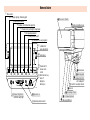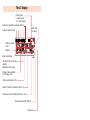
1
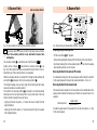
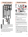
TV. VIDEO. AUDIO. MECABLITZ
ķ
Note:
Within the framework of the CE approval symbol, correct exposure was
evaluated in the course of the electromagnetic compatibility test.
Do not touch the SCA contacts !
In exceptional cases the unit can be
damaged if these contacts are touched.
MECABLITZ 40 MZ-3i
TV • VIDEO • CAMCORDER • MECABLITZ
Initiative
für natürliche
Umwelt
METZ-Werke GmbH & Co KG
Ohmstraße 55 • 90513 Zirndorf
Telefon (0911) 9706-0 • Fax (0911) 9706-340
Internet: http://www.metz.de
E-Mail: [email protected]
Operating Instructions
796 47 0111.A4
ķ
Nomenclature
Main switch
LC display lighting / Modelling light
Main zoom reflector
Aperture preselector
Battery compartment cover
Cordless control (Remote operation)
Preselector for partial light output levels
Film speed preselector
Beep function on/off
Preselector for user programs
± Buttons for
value adjustment
Locking key
Preselector for
manual zoom
control
Multi-function key
Auto off
Rapid pos.
Normal pos
MB 40 MZ-3
Manual firing button
and flash-ready light
Exposure o.k.
Operating mode selector
Rotary base
Clamping plate
Standard Foot 301
or SCA-Adapter*
Switch for secondary reflector
Sensor
Secondary reflector
AF-measuring beam
Wide-angle diffuser
The LC display
Program place:
0 = Work surface
1-9 = User programs
Symbols for switched-on secondary reflector
Zoom reflector setting
Display of operating mode
Distance in meters
or feet
Aperture
Battery warning indicaPre-flash function for red-eye
reduction
(depends on camera type)
Storage of values indicated
on LC display = STO
Calling a user program = RCL
Number of flashes in stroboscopic mode = N
Flashes per second in stroboscopic mode = f (Hz)
Acoustic exposure verification ON
Film speed
Contents
Foreword . . . . . . . . . . . . . . . . . . . . . . . . . . . . . . . . . . . . . . . . . .4
1. Safety instructions . . . . . . . . . . . . . . . . . . . . . . . . . . . . . .6
2. Preparations . . . . . . . . . . . . . . . . . . . . . . . . . . . . . . . . . . .7
Suitable batteries . . . . . . . . . . . . . . . . . . . . . . . . . . . . . .7
Loading and replacing the batteries . . . . . . . . . . . . . . . . .8
Battery warning indicator . . . . . . . . . . . . . . . . . . . . . . . .9
Mounting the mecablitz on the camera . . . . . . . . . . . . . .10
Switching the mecablitz on and off . . . . . . . . . . . . . . . .11
3. TTL flash mode . . . . . . . . . . . . . . . . . . . . . . . . . . . . . . . .12
TTL Easy-Mode . . . . . . . . . . . . . . . . . . . . . . . . . . . . . . .14
4. Automatic flash mode . . . . . . . . . . . . . . . . . . . . . . . . . . .15
5. Manual flash mode . . . . . . . . . . . . . . . . . . . . . . . . . . . . .18
6. Bounce flash . . . . . . . . . . . . . . . . . . . . . . . . . . . . . . . . . .20
with secondary reflector . . . . . . . . . . . . . . . . . . . . . . . .22
in auto and TTL modes . . . . . . . . . . . . . . . . . . . . . . . . .23
in manual mode . . . . . . . . . . . . . . . . . . . . . . . . . . . . . .23
7. Metz cordless TTL remote operation . . . . . . . . . . . . . . . .24
Metz cordless auto remote operation . . . . . . . . . . . . . . .28
8. Winder mode . . . . . . . . . . . . . . . . . . . . . . . . . . . . . . . . . .31
Using the winder in the manual mode . . . . . . . . . . . . . .31
Using the winder in auto and TTL modes . . . . . . . . . . . .31
9. Working with partial light output levels . . . . . . . . . . . . .32
Partial light output levels in the auto mode . . . . . . . . . . .32
Partial light output levels in the manual mode . . . . . . . . .32
Flash durations . . . . . . . . . . . . . . . . . . . . . . . . . . . . . . .34
Macrophotography (close-ups) . . . . . . . . . . . . . . . . . . . .34
10. Stroboscopic mode . . . . . . . . . . . . . . . . . . . . . . . . . . . . .35
2
Contents
11. Fill-in flash in daylight . . . . . . . . . . . . . . . . . . . . . . . . . .38
Fill-in flash in auto mode . . . . . . . . . . . . . . . . . . . . . . . .38
Fill-in flash in manual mode . . . . . . . . . . . . . . . . . . . . .39
Fill-in flash in TTL mode . . . . . . . . . . . . . . . . . . . . . . . .40
12. Working with user programs . . . . . . . . . . . . . . . . . . . . . .41
Calling a user program. . . . . . . . . . . . . . . . . . . . . . . . . . . 42
Storing a program . . . . . . . . . . . . . . . . . . . . . . . . . . . . . . 43
13. The zoom reflector . . . . . . . . . . . . . . . . . . . . . . . . . . . . . . . 44
The Ex-Zoom mode (extended zoom) . . . . . . . . . . . . . . . . 44
Wide angle diffuser . . . . . . . . . . . . . . . . . . . . . . . . . . . . . 46
14. Special functions . . . . . . . . . . . . . . . . . . . . . . . . . . . . . . . . 47
Correct exposure indicator „o.k.“ . . . . . . . . . . . . . . . . . . . 47
AF measuring beam . . . . . . . . . . . . . . . . . . . . . . . . . . . . . 48
The ML function(Modelling Light) . . . . . . . . . . . . . . . . . . . 49
The Beep function (acoustic alarm) . . . . . . . . . . . . . . . . . 50
Locking the controls. . . . . . . . . . . . . . . . . . . . . . . . . . . . . 51
Automatic cut-out . . . . . . . . . . . . . . . . . . . . . . . . . . . . . . 52
The Rapid function . . . . . . . . . . . . . . . . . . . . . . . . . . . . . . 52
m - ft display . . . . . . . . . . . . . . . . . . . . . . . . . . . . . . . . . . 53
15. Exposure corrections . . . . . . . . . . . . . . . . . . . . . . . . . . . . . 54
Exposure corrections in auto mode . . . . . . . . . . . . . . . . . 54
Exposure corrections in TTL mode . . . . . . . . . . . . . . . . . . 54
16. Technical data. . . . . . . . . . . . . . . . . . . . . . . . . . . . . . . . . . . 55
17. Optional extras . . . . . . . . . . . . . . . . . . . . . . . . . . . . . . . . . . 62
18. Troubleshooting hints. . . . . . . . . . . . . . . . . . . . . . . . . . . . . 64
Alphabetical index . . . . . . . . . . . . . . . . . . . . . . . . . . . . . . . 66
3
Foreword
Foreword
Congratulations on purchasing this Metz flashgun, and thank you for your confidence in Metz equipment.
It is only natural that you should want to use your flashgun straight away. However, it
will be well worth your while to study these Operating Instructions beforehand to
ensure that you can operate the flashgun effectively and without any problems.
Please also open the back cover page with the illustrations.
•40 MZ-3(i) with
SCA 3000-adapter
Automatic flash mode, ch. 4, p. 15
TTL flash mode*,, ch. 3, p. 12
TTL Easy Mode*, ch. 3, p. 14
Manual flash mode, ch. 5, p. 18
Metz TTL remote mode*, ch. 7, p. 24
Metz automatic remote mode, ch. 7.1., p. 28
Stroboscopic mode, ch. 10, p. 35
This flashgun can be used with:
* If the camera supports this function.
•All cameras with a hot shoe contact
•All cameras with accessory shoe without hot-shoe contact, and with a synch
cable (see Optional Extras)
•System cameras
Optimal adaptation to your camera is achieved by using an SCA adapter. The enclosed
SCA 300/3000 table will indicate the adapter you require for your particular camera
model. This table also informs you about the special flash functions that can then be
completed by the given system.
Brief survey of the operating functions:
Configuration
Possible operating modes
•40 MZ-3(i) with
301 standard foot
Automatic flash mode, ch. 4, p. 15
Manual flash mode, ch. 5, p. 18
Metz automatic remote operation, ch. 7.1, p. 28
Stroboscopic mode, ch. 10, p. 35
•40 MZ-3(i) with
SCA 300 adapter
The SCA 3000 adapter is the most convenient link to your camera! The ISO, zoom
and aperture data are transmitted, depending upon the camera configuration!
General operating instructions
The subsequent instructions are of a general nature. The procedures identified by
red numbers must be completed when using a system camera in conjunction
with an SCA 3000 adapter.
All steps identified with an asterisk * must be additionally adjusted, depending
upon the given type of camera.
In conjunction with the Canon SCA adapter 3101 M3, this flashgun permits
Canon E-TTL operating.
The flashgun is suitable for APS cameras that feature an accessory shoe
with hot shoe contact.
Automatic flash mode, ch. 4, p. 15
TTL flash mode*, ch. 3, p. 12
TTL Easy Mode*, ch. 3, p. 14
Manual flash mode, ch. 5, p. 18
Metz TTL remote operation*, ch. 7.1, p. 24
Metz automatic remote mode, ch. 7.1., p. 28
Stroboscopic mode, ch. 10, p. 35
* If the camera supports this function.
4
5
1. Safety Instructions
2. Preparations
Never fire a flash in the immediate vicinity of the eyes!
Flash fired directly in front of the eyes of a person or animal can
damage the retina and lead to severe visual disorders - even blindness!
Exhausted batteries should be immediately removed from the flashgun!
Lye leaking out of dead batteries will damage the flash unit.
or
ad
NiC
tery
bat
H
NiM
Suitable batteries
ries
atte
b
e
nes
nga
a
em
alin
Alk
ries
atte
b
ium
Lith
Never recharge dry-cell batteries such as alkaline manganese and
lithium batteries!
Never short-circuit rechargeable batteries!
Do not expose batteries to excessive heat, for instance sunshine, fire
and the like!
Fig. 1: Suitable AA-size batteries
Never throw exhausted batteries on a fire!
The flashgun can be operated with any of the following batteries:
Do not expose the flashgun to dripping and splashing water!
Protect the flashgun against excessive heat and humidity! Do not store
the flashgun in the glove compartment of a car!
• 4 NiCad rechargeable batteries, type IEC KR 15/51.
They ensure fast recycling times and are very economical as they can be
recharged over and over again.
Make sure to tighten the knurled screw firmly so that the flashgun cannot slip off!
• 4 nickel metal hydride batteries. They have a much higher capacity than
NiCad batteries and have less impact on the environment because they are
free from cadmium.
When taking a sequence of pictures at full light output and fast recycle
times during NiCad battery operation, shooting should be interrupted for
at least 3 minutes after every 15 flashes, in order to prevent overloading.
Never place material that is impervious to light in front of, or directly on,
the reflector screen. The reflector screen must be perfectly clean when a
flash is fired. The high energy of the flash light will burn the material or
damage the reflector screen if this is not observed!
• 4 alkaline-manganese batteries, type IEC LR6.
Maintenance-free power source for moderate requirements.
• 4 lithium batteries, type FR6 L91.
Can be stored for many years with virtually no loss of power, thus making
them ideal for occasional use.
• Power Pack P 40 (optional extra)
Provides microprocessor controlled battery monitoring and state-of-charge
indication (with discharge function).
• Power Grips G 15/16 (optional extra)
Convert a compact flashgun into a handle-mount unit.
6
7
2. Preparations
Loading the batteries
2. Preparations
Battery warning indicator
Fig. 2: Position of batteries
Fig. 3: The battery warning indicator
Loading and replacing the batteries
The battery warning indicator
•Switch off the flashgun with the main switch .
•Push the battery compartment cover in direction of the arrow as far as
possible.
facility is a testing aid for alkaline manganese batteries only. It is
☞ This
of no significance for other battery types.
•Insert the batteries lengthwise into the compartment.
When inserting the batteries ensure that their polarity is correct, as
indicated by the symbols in the battery compartment!
•Close the battery compartment cover .
batteries must not be thrown into the dustbin! Contribute
☞ Exhausted
to the protection of the environment and discard dead batteries at the
If the flashing battery symbol appears, the remaining energy is still sufficient for
a limited number of flashes. Some battery models may cause the warning indicator to flash prematurely, with about 50 % of their capacity left. Such batteries
should be replaced only when really discharged (if recycling takes longer than 60
sec.).
The condition of the batteries can only be checked if the flashgun is switched on
and after a few flashes have been fired.
appropriate disposal points.
8
9
2. Preparations
Mounting
2. Preparations
Mounting, switching on and off
Cover plate
Fig. 4: Fixing the flashgun
Fig. 5: Removing the Foot or SCA adapter
Mounting the flashgun on the camera
•Push the SCA adapter or Standard Foot 301 all the way in.
The flashgun can only be attached to the camera with the Standard Foot 301 or
an SCA 300/SCA 3000 adapter (optional extra).
mounting or removing the flashgun, switch off both the camera
☞ Before
and the flashgun
Slip the flashgun into the camera’s accessory shoe and lock it into position by
turning down the knurled screw .
The standard 40 MZ-3(i) version comes with the Standard Foot 301 which provides simple flash synchronisation, while the „Set“ version is supplied with the corresponding
SCA adapter.
Removing the Standard Foot or SCA adapter:
1 Hold the rotary base of the flashgun and swivel the body by 90°.
2 Press the retention catch in direction of the arrow.
3 Withdraw the Standard Foot or SCA adapter.
Mounting the Standard Foot or SCA adapter:
•Hold the cover plate (only when using the SCA 3000 adapter) in the centre and
withdraw.
10
•Reset the rotary base to its original position
Synch connection between flashgun and camera is automatically established
when the flashgun is inserted into the camera’s accessory shoe.
On cameras without a hot shoe, synchronisation is achieved with a synch cable
(36-50, normal, or 36-52, coiled).
Switching the flashgun on and off
The flashgun is switched on with the main switch . It is permanently on when
in ON position.
To switch off, push the main switch to the lower position.
☞ CAUTION! If the locking switch is in the upper position, read the
instructions under the heading "Switching on with the controls
locked" on Page 51.
If the flash unit is not going to be used for a prolonged period we
recommend:
- Switch off the flash unit with the main switch
- Remove the source of power (batteries).
11
3. TTL flash mode
3. TTL flash mode
1
Sensor
2
Fig.6 : Measuring scheme for TTL mode
Fig. 7: Settings for TTL mode
The direct way to good flash shots
Setting procedure for TTL mode:
Ǻ
In TTL mode, the exposure readings are made by the sensor built into the
camera (Fig. 6). This sensor measures the light reaching the film through the
camera lens. An electronic control circuit within the camera transmits a stop
signal to the flashgun as soon as the film has been exposed by the correct
amount of light; the flash is then instantly cut out.
The advantage of this flash mode is that all factors influencing the correct exposure
of the film, such as filters, change of aperture and focal length with zoom lenses,
extensions for close-ups, etc. are automatically taken into account.
TTL flash mode can only be carried out with cameras that feature
☞ The
this function. The flashgun must be fitted with a corresponding SCA
adapter (see SCA 300/3000 system instructions and SCA survey table).
Exposure corrections may be necessary with pronounced differences
in contrast, for instance dark objects in snow (see ch. 15, p. 54).
•Adjust the camera according to the manufacturer’s Operating Instructions.
•Fit the flashgun with the appropriate SCA adapter and mount it on the camera.
1 Switch on the flashgun with the main switch .
2 Set the operating mode selector to TTL.
• *Press the ISO button and adjust the film speed with the „+“ or „-“
button .
• *Press the ZOOM button and use the „+“ or „-“ button to adjust the
zoom value selected with the camera’s lens.
• If necessary, press the P button and adjust the partial light output level with
the „+“ or „-“ button (e.g. in winder mode).
and use the „+“ or „-“ button to adjust the same
*Press
the button
•
aperture as on the camera.
*must
additionally be set on some cameras.
the event that film speed and aperture are not transmitted auto☞ Inmatically,
there is no need to make these settings manually; they are
insignificant for a correct exposure. They are, however, necessary for
correct indication of the distance.
12
13
3. TTLflash mode
4. Automatic flash mode
Easy Mode
1
2
Fig. 8: Settings for TTL Easy Mode
This is the simplest way to operate the mecablitz in TTL flash mode. All buttons
on the mecablitz are locked, with the exception of the /ML and buttons.
In TTL Easy Mode with the SCA 300 adapter, the zoom position is constantly adjusted
to 28 mm to ensure that the subject is always adequately illuminated.
In TTL Easy Mode with the SCA 3000 adapter, the zoom setting is matched to the
focal length of the lens, and a distance range is indicated, provided that the
camera supplies the zoom information.
We recommend the TTL Easy Mode when using an SCA 300 adapter.
Distance indication on the LC display is not possible in this mode.
Setting procedure for TTL Easy Mode:
•Adjust the camera according to the manufacturer’s operating instructions.
Sensor
Fig. 9: Measuring scheme for auto mode
Ǻ
In the auto flash mode, the flash unit’s sensor measures the light reflected
from the subject. The flash is cut off as soon as sufficient light has been emitted for correct exposure.
This eliminates the need to recalculate and readjust the aperture each time the
distance is changed, provided that the subject remains within the indicated auto
flash range.
The flash unit’s sensor must be directed at the subject, regardless of the direction
at which the main reflector is pointing. The sensor has a measuring angle of
approx. 25° and takes measurements only during the emission of light by the
flashgun in which it is integrated.
In the auto mode, also partial light output levels can be adjusted (see ch. 9, p.32).
Between six and twelve working apertures are available in the auto mode,
depending upon the adjusted ISO film speed.
•Fit the mecablitz with the corresponding SCA adapter and mount it on the
camera.
1 Switch on the mecablitz with the main switch .
2 Adjust the operating mode selector to EM.
14
15
4. Automatic flash mode
4. Automatic flash mode
The permissible distance range and the corresponding aperture appear on the
LC display.
The subject should be located within the middle third of this distance
range, thus giving the electronic control sufficient scope for compensation, if necessary.
1
☞
There is a certain measure of overlap between the individual working apertures.
As a result of this overlap it is always possible to place the subject within the
middle third of the range.
Caution with zoom lenses!
2
☞
Fig. 10: Settings for the auto mode
Setting procedure for auto flash mode:
•Adjust the camera according to the manufacturer’s Operating Instructions.
1 Switch on the flashgun with the main switch .
2 Set the operating mode selector to A.
Due to their design they can cause a loss of light in the order of up to
one f-stop. Furthermore, the effective aperture can also vary, depending upon the adjusted focal length.This can be compensated by
correcting the aperture on the flashgun manually!
• *Press the ISO button and set the film speed with the „+“ or „-“ button .
• *Press the Zoom button and use the „+“ or „-“ button to enter the zoom
value selected on the camera lens.
• If necessary, press the P button and adjust a partial light output level with
the „+“ or „-“ button (see ch. 9, p. 32).
• *Press the button and adjust the automatic aperture with the „+“ or „“ button until the desired distance range is indicated. This aperture must
also be set on the camera lens.
*must
additionally be set on some cameras
SCA 3000 adapter is used, some cameras automatically transmit
☞ Iftheanf-number
to the flash unit also in the auto flash mode. Should this
be the case, the auto aperture need not be set on the flashgun.
16
17
5. Manual flash mode
5. Manual flash mode
1
4
3
Fig. 11: Shot with direct flashlight
Fig. 12: Settings for manual mode
• Distance to the subject
Setting procedure for manual flash mode:
• Adjust the camera according to the manufacturer’s Operating Instructions.
1 Switch on the flashgun with the main switch .
2 Set the operating mode selector to M.
• *Press the ISO button and set the film speed with the „+“ or „-“ button
.
• *Press the Zoom button and use the „+“ or „-“ button to set the zoom
value that matches the focal length of the camera lens
3 Press the button • Desired aperture
4 Use the „+“ or „-“ button to change the aperture on the flash unit until the
Ǻ
In this mode, the flashgun will always emit its full power.
2
Adaptation to the actual picture shooting situation is by setting the
corresponding aperture on the lens.
A single value for the flash-to-subject distance appears on the LC display while in
manual mode.
If the displayed value does not coincide with the actual distance, then the aperture
and/or partial light output level have to be changed accordingly (see ch. 9, p. 32).
The decisive points for the partial light output level are:
• ISO film speed
• Zoom position of the reflector
The sensitive selection of partial light output levels makes it possible
to adjust the distance to the subject in very small increments in the
manual flash mode.
☞
desired distance appears on the LC display. This f-number must also be set on
the camera lens.
SCA 3000 adapter is used, some cameras automatically transmit
☞ Iftheanf-number
to the flash unit. Should this be the case, the f-number
on the camera must be changed until the flash unit’s LC display
indicates the desired distance.
*must
18
additionally be set on some cameras
19
6. Bounce flash
Fig. 13: Bouncing the flash (The photo was shot with the flash bounced off the right wall)
Ǻ
Photos shot with full frontal flash are easily recognized by their harsh, dense
shadows. This is often associated with a sharp drop of light from the foreground to the background.
This phenomenon can be avoided with bounce flash because the diffused
light will produce a soft and uniform rendition of both the subject and the
background. For this purpose the reflector is turned in such a manner
that the flash is bounced off a suitable reflective surface (e.g. ceiling or
walls of a room).
The reflector can be turned vertically and horizontally. The vertical lock-in positions
for bounce flash are:
• 60°, 75° and 90° (simply tilt the reflector to the required angle)
6. Bounce flash
Fig. 14: Lock-in positions of reflector and head
When turning the reflector , or flash head, it is essential to ensure that it is moved
by a sufficiently wide angle so that direct light can no longer fall on the subject.
Therefore, always turn the reflector or head at least to the first lock-in position.
The diffused light bounced back from the reflective surfaces results in a soft illumination of the subject.
The reflecting surface must be white or have a neutral colour and it must not
be structured (e.g. wooden beams in a ceiling), as these might cast shadows.
For colour effects just select reflective surfaces in the desired colour.
Use of the secondary reflector is advantageous to avoid disturbing dense
shadows with bounce flash, for instance under the nose and in the eye sockets,
in portraiture.
Ǻ
The flash head can be swivelled horizontally through 270°, and locks into position
at 60°, 90°, and 180°.
distance values on the LC display disappear as soon as the reflector
☞ The
is tilted upwards or the flash head turned horizontally. The distance from
the flashgun to the ceiling or wall and from there to the subject is now an
unknown factor.
20
21
6. Bounce flash
with secondary reflector
Fig. 15: Bounce flash with switched-on secondary reflector
Ǻ
6. Bounce flash
Fig. 16: Switching on the secondary reflector - Display
The secondary reflector produces frontal fill-in light when bouncing the flash.
Mounting the light reducing filter:
of the secondary reflector is only advisable for bounce flash
☞ Use
photography.
•Tilt the main reflector 90° upwards.
The secondary reflector is switched on and off with the switch
.
Symbols on the LC display
indicate that the secondary reflector is on
(Fig. 16). If these symbols flash, you are advised that the main reflector is not tilted and that use of the secondary reflector is not expedient.
•Remove the required light reducing filter from the back of the main reflector.
•Slip the light reducing filter on the secondary reflector , over the AF measuring
beam aperture, and allow it to lock in place.
Bouncing the flash in the auto and TTL modes
When the secondary reflector is activated, 90% of the light will be emitted by the
main reflector , and approx. 10% by the secondary reflector .
It is advisable to check prior to the actual exposure whether the light is sufficient
for the selected aperture. Proceed in the manner described in ch. 14, p. 47.
The stated percentages may vary when using the flash with partial light output
levels and switched-on secondary reflector.
If the light from the secondary reflector is too bright, it can be diminished by
attaching one of the two light reducing filters. They are at the back of the main
reflector and their characteristics are as follows:
Bouncing the flash in the manual mode
•1 light grey filter with the symbol „-1“ reduces the amount of light to half the
original brightness.
•1 dark grey filter with the symbol „-2“ reduces the amount of light to one quarter
of the original brightness.
22
The required camera aperture in the manual mode is best established with an
exposure meter. Observe the following rule of thumb if an exposure meter is not
available:
Camera aperture =
Guide number
Light distance x 2
to establish a guide value for the aperture that can then be varied by + 1 f-stop
for the actual exposure.
23
7. Metz cordless TTL remote operation
7. Metz cordless TTL remote operation
Controller
TTL remote operation
50 MZ-5
50 MZ-5
Controller
adj. to TTL
Controller
adj. to TTL
SCA 300 D
only with
SCA 3_ _ _
40 MZ-1(i)
40 MZ-2
40 MZ-3(i)
auf TTL
SCA 300 D
only with
SCA 3_ _ _
SCA 312/2AF
SCA 332/2AF
SCA 333/2AF
SCA 346/2AF
SCA 356
SCA 374/2AF
SCA 381/2AF
SCA 312/2AF
SCA 332/2AF
SCA 333/2AF
SCA 346/2AF
SCA 356
SCA 374/2AF
SCA 381/2AF
SCA 3_ _
SCA 3_ _
Slave
40 MZ-1(i)
40 MZ-2
40 MZ-3(i)
auf TTL
50 MZ-5
Slave
40 MZ-1(i)
40 MZ-2
40 MZ-3(i)
adj to TTL
SCA 3080
Ǻ
Here, „remote operation“ means cordless firing of additional (slave) flashguns. The master flashgun (controller) mounted on the camera controls the
additional flash units (slaves) in such a manner that automatic exposure
control in TTL mode is extended to all slaves.
The Metz TTL remote operation permits joint cordless TTL flash control of several
40 MZ-.. and 50 MZ-5 flash units. For this purpose all slaves must be fitted with an
SCA 3080 Slave Adapter which is available as an optional extra. The slaves can be
mounted on the stand supplied with the SCA 3080 or on a tripod.
24
1
4
3
2
5
Fig. 17: Settings for TTL remote operation
Setting procedure for Metz TTL remote operation:
• Adjust the camera to TTL mode, as explained in the manufacturer’s Operating
Instructions.
1 Switch on the flashgun mounted on the camera with the main switch .
2 Set the operating mode selector to TTL.
3 Press the Remote button on the flashgun mounted on the camera.
4 Use the „+“ button to select the controller address Co 1 or Co 2.
• Fit each slave with an SCA 3080 Slave Adapter, switch on with the main switch ,
and set the operating mode selector to TTL: The slaves are now in slave mode.
5 Press the manual firing button on the flashgun mounted on the camera and
fire a test flash.
• The slave unit responds with a delayed flash, thus confirming that it is ready
for operation. If several slaves are used at the same time, all will react simultaneously. The LC display indicates SL 1 or SL 2, depending on the controller
address selected (Fig. 17). If, after a test flash has been fired, proper function
is not confirmed by one of the slave units in the form of a delayed flash, then
the sensor in the SCA adapter has not received any light pulse. Should this
be the case, rotate the rotary base of the flash unit so that the sensor can receive a light pulse, and repeat step 5.
25
7. Metz cordless TTL remote operation
7. Metz cordless TTL remote operation
Indication that flash readiness has been reached is particularly important for
TTL remote operation. If flash readiness is established, the AF measuring beam
on the slave gives brief light pulses and the flash-ready indicator is lit. If
the slave units have been set up in such a manner that their visual signs are
not visible to the user, then the Beep function can be activated so that an acoustic signal is generated when flash readiness is reached (see ch. 14, p. 50).
Switching off the Metz TTL remote operation:
Fig. 18: Display for operation with slaves
particularly short distance between controller and slave unit may
☞ Acause
the camera’s electronics to cut off the flash before the slave
• Press the Remote button on the controller twice.
• On the slave unit:
Switch off the flashgun, remove the Slave Adapter SCA 3080 and switch on
the flashgun again.
has received its light pulse. In such an event widen the distance or
choose a larger f-number and repeat step No. 5.
To ensure that two TTL remote systems in the same room do not interfere with
each other, two different addresses can be selected on the controller. These are
then automatically transferred to the slave units after a test flash.
Checking the slave address:
The Co1 or Co2 controller address is permanently adjusted after a test flash has
been fired in the manner described in step No. 5. The address setting can only be
changed by switching the slave off and on again, and by repeating the steps No.
4 and 5. Please check the display to establish the address to which the slave has
been adjusted. Co1 and SL1 indicate that the controller and slave unit are both
adjusted to address 1. Alternately, Co2 and SL2 indicate address 2.
rA1 and rA2 (not with SCA 3080-M1 adapter) in the distance range indication on
the LC display can be ignored in these instances.
26
27
7.1 Metz cordless auto remote operation
Metz A remote operation can be used with system, standard, old
☞ The
mechanical and medium-format cameras.
Controller
A-Remote-Operation
50 MZ-5
50 MZ-5
Controller
adj. to A
Controller
adj. to A
SCA 301
SCA 3_ _ _
SCA 300 D
nur bei
SCA 312/2AF
SCA 332/2AF
SCA 333/2AF
SCA 346/2AF
SCA 356
SCA 374/2AF
SCA 381/2AF
40 MZ-1(i)
40 MZ-3(i)
adj. to A
SCA 300 D
onlly with
SCA 312/2AF
SCA 332/2AF
SCA 333/2AF
SCA 346/2AF
SCA 356
SCA 374/2AF
SCA 381/2AF
40 MZ-1(i)
40 MZ-3(i)
adj. to A
SCA 301
SCA 3_ _ _
SCA 3_ _
Slave
SCA 3_ _
50 MZ-5
Slave
28
The only precondition is that all cameras feature a synch
contact/socket, and are equipped with a 301 Standard Foot or SCA
adapter.
Setting procedure for Metz A remote operation:
• Adjust the camera to manual mode as explained in the manufacturer’s operating
instructions.
• Set a shutter synch speed of 1/60th sec. or slower on the camera.
• Switch on the master flashgun (controller) attached to the camera with the
main switch .
• Adjust the operating mode selector to A.
• Press the Remote button on the mecablitz mounted on the camera. The
distance values on the LC display disappear.
40 MZ-1(i)
40 MZ-2
40 MZ-3(i)
adj. to TTL
SCA 3080
Ǻ
7.1 Metz cordless auto remote operation
In the Metz A remote mode the master flashgun (controller) mounted on
the camera controls the slaves in such a manner that automatic operation
covers all slave units. The exposure is controlled by the sensor on the
controller. To implement this mode, all 40 MZ-.. slave units must first be
fitted with an SCA 3080 Slave Adapter (available as an optional extra).
50 MZ-5 slaves do not require a slave adapter.
• Select the controller address Co 1 or Co 2 with the + button .
• Fit the 40 MZ-.. slave units with an SCA 3080 Slave Adapter; switch on with the
main switch and adjust to TTL. The 40 MZ-.. slaves are now in slave mode. Separate the 50 MZ-5 slaves from the controller, and switch on with the main switch.
• Press the manual firing button on the controller attached to the camera,
and fire a test flash.
• The slave will respond with a delayed flash, thereby indicating that it is ready for
operation. All slave units simultaneously acknowledge operating readiness when
several slaves are being jointly used. If you find that a slave unit does not respond, this may indicate that the sensor on the slave did not receive a light pulse. Turn the flashgun in such a manner that the sensor can receive the light
pulse from the master flash (controller). Now fire another test flash. A
particularly short distance between master flash and slave can result in overmodulation of the sensor. In this case widen the distance and repeat the test flash.
29
7.1 Metz cordless auto remote operation
Proceed as described in ch. 7 to check and change the slave address, and to
switch off automatic remote operation. To assess the overall lighting conditions,
press the ML button for at least 2 seconds. This willl trigger a modelling light
(approx. 4 seconds). All slaves (40 MZ-1(i) and MZ-3(i) with SCA 3080 M-1 adapter) likewise emit a modelling light.
8. Winder mode
Ǻ
The winder mode involves shooting a sequence of pictures at a rate of
several frames per second. It is a manual mode with partial light output
levels, and is only recommended with NiCad batteries or high-power alkaline manganese batteries. Table 5 of the Technical Data indicates which
partial light output level is suited for a given frame frequency (frames per
second = flashes per second).
Using the winder in the manual mode
In the manual mode, the exposures are made with a fixed partial light output level
selected in conformity with the winder data given in Table 5 of the Technical Data.
Using the winder in auto and TTL modes
In these modes it is possible to ensure that a flash will be fired with each exposure
of a series of pictures. For this purpose a partial light output level can be adjusted in
conformity with the winder data (Table 5).
that require less light are automatically controlled by the auto☞ Shots
matic or TTL light output system and are, therefore, correctly exposed.
Shots that require more light than the adjusted partial light output
level may be underexposed!
30
31
9. Working with partial light output levels
Ǻ
9. Working with partial light output levels
Partial light output levels are manually adjustable fractions of the full-power
light output.
4
1
Partial light output levels can be set in all operating modes except the TTL remote
mode. The recycling times are shorter when partial light output levels are adjusted
(see Technical Data, Table 1) instead of full-power flashes. At the same time the guide
number of the flashgun is diminished, together with the flash-to-subject distance or
flash range, because only part of the flash power is emitted.
Partial light output cannot be set for TTL remote operation. In stroboscopic mode, the maximum possible partial light output is always
indicated.
Fig. 19: Partial light output levels in the manual mode
Partial light output levels in the auto mode
Setting procedure for manual mode with partial light output:
Partial light output may be adjusted in the auto mode to ensure that a flash is
always triggered with serial shots (winder mode).
• Adjust the camera in the manner described in the operating instructions.
1 Switch on the flashgun with the main switch .
2 Adjust the operating mode selector to M.
5
☞
The actual light output level for a given flash frequency and number of flashes is
specified in Table 5 of the Technical Data.
Partial light output levels in the manual mode
Some situations make it necessary to reduce the amount of light emitted by the
flashgun because the selected flash-to-subject distance may result in an
excessively high f-number and undesired large depth of field. This is where the
partial light output level function comes to the rescue.
The partial light output levels are adjustable within very close increments. The
distance value of the flashgun can therefore be easily matched to the subject
distance if a specific aperture has to be retained. Thus, professional flash photography is made possible in a very simple manner to deal with difficult situations
(great differences in contrast, extreme level of reflection) when the automatic
system would not produce optimal results.
32
3
2
• *Press the ISO button and then adjust the film speed with the + or
- button • *Press the Zoom button and use the + or - button to adjust the zoom
value that equals the focal length of the camera lens.
3 Press the button.
4 Use the + or - button to continuously change the flashgun’s aperture until
the required aperture appears on the LC display. Now set the same aperture
on the camera.
If an SCA 3000 adapter is used, some cameras automatically transmit
the f-number. Should this be the case, the aperture on the camera
must be changed until the required f-number appears on the LC
display of the flashgun.
5 Press the P button , and then use the + or - button to continuously
change the partial light output level until the required distance appears on
the LC display.
* must additionally be set on some cameras
☞
33
9. Working with partial light output levels
10. Stroboscopic mode
Flash durations
The adjustable partial light output levels result in different flash durations (see
Technical Data, Table 1). The specified flash durations apply only to single flashes
in manual mode. With serial flashes (winder or stroboscopic mode) the last
flashes may have a longer duration. Flash duration in the auto and TTL modes
can also be shorter when the automatic exposure control switches off the flash at
an earlier moment.
Macrophotography (close-ups)
Parallax error can be compensated by tilting the main reflector downwards by
-5° or -13°. For this purpose pull the reflector completely out, and then tilt it
down.
With close-up photography it is important to ensure that a certain minimum
lighting distance is maintained to avoid overexposure.
For exposures with extremely short flash-to-subject distances, we advise you to
use small partial light output levels in manual mode, as described on page 32.
Fig. 20: Stroboscopic mode
Ǻ
In this mode several flash exposures are made on the same frame. This is
particularly interesting for motion studies and for special effects (Fig. 20).
In stroboscopic mode, several flashes are fired at a certain flash frequency.
Consequently, this function is only possible with a partial light output level of 1/4
max. or less.
For a stroboscopic exposure it is possible to select a flash frequency of 1...30 Hz
in 1 Hz increments, and a number of flashes of 2...20 in single increments.
The maximum possible partial light output level in stroboscopic mode is automatically adjusted (see Technical Data, Table 5). The partial light output level can
be adjusted manually to the minimal value of 1/256 to achieve short flash durations.
The LC display indicates the distance applicable to the adjusted parameters. The
displayed distance value can be adjusted to the actual shooting distance by varying the f-stop or the partial light output level. The aperture adjusted on the flashgun must be transferred to the camera. The distance range can be increased by
loading a high-speed film.
of the stroboscopic mode is not possible when the secondary
☞ Use
reflector is switched on.
34
35
10. Stroboscopic mode
10. Stroboscopic mode
. Then use the „+“ or „-“ button to select an aperture
button
that matches the distance to the subject.
Set this aperture also on the camera.
*must additionally be set on some cameras
• *Press the
1
4/6
2
5
3
distance to the moving subject is used as the distance value. To
☞ The
prevent overexposure of the motionless background this should
either be very dark or far behind the moving subject. The best results
are achieved at a low ambient light level.
Fig. 21: Settings for stroboscopic mode
Table 5 of the Technical Data specifies the maximum partial light output levels for
the N - f(Hz) combinations.
Setting procedure for stroboscopic mode:
Ensure that an adequately slow shutter speed is set on the camera.
• Adjust the camera to manual mode, as explained in the manufacturer’s Operating
Instructions, and select the matching shutter speed (see Technical Data, Table 5).
1 Switch on the flashgun with the main switch .
Table 6 of the Technical Data specifies the fastest shutter speeds for the N - f(Hz)
combinations.
• If the film speed has not yet been set on the mecablitz:
- Adjust the operating mode selector to A.
- Press the ISO button and set the film speed with the „+“ or „-“ button 2 Adjust the operating mode selector to
.
• *Press the Zoom button and use the „+“ or „-“ button to set the zoom
value selected on the camera lens.
3 Press the button N (double function of the ISO button).
4 Enter the desired number of flashes N with the „+“ or „-“ button .
5 Press the f(HZ) button (double function of the button.
6 Enter the desired flash frequency f(Hz) with the „+“ or „-“ button .
• If necessary, press key P and use the „+“ or „-“ button to reduce the
partial light output level.
36
37
11. Fill-in flash in daylight
11. Fill-in flash in daylight
☞
When shooting into the light ensure that the backlight does not shine
directly onto the sensor as this will confuse the flashgun’s electronics.
Fill-in flash in manual mode
The partial light output levels can be used in manual flash mode to achieve the
desired brightening effect of fill-in flash.
Complete illumination of shadow areas
Fig. 22: Fill-in flash in daylight
The mecablitz can also be used for fill-in flash in daylight to soften harsh shadows
and lower the contrast, thereby producing a more balanced exposure when
shooting against the light. Various possibilities are open to the user for fill-in flash.
Fill-in flash in auto mode
Use the camera, or a hand-held exposure meter, to establish the required aperture
and shutter speed for a normal exposure. Ensure that the shutter speed either equals,
or is slower than, the fastest flash synch speed (varies with different camera models).
Example:
Established aperture = f/8; established shutter speed = 1/60th sec.
Flash synch speed of the camera e.g. 1/100th sec. (see operating instructions for
the given camera).
The two established values for aperture and shutter speed can be set on the
camera because the camera’s shutter speed is slower than the camera’s flash
synch speed.
To maintain a balanced range of highlights, for instance in order to retain the
character of the shadows, it is advisable to select the automatic aperture on
the flashgun one setting lower than the aperture adjusted on the camera. In
our example f/8 was set on the camera. Consequently, we advise you to adjust
f/5.6 as the aperture setting on the flashgun.
38
Use the camera, or a hand-held exposure meter, to establish the required aperture and adjust this value on both the camera and flashgun. The aperture adjusted
on the camera is automatically transferred to the flashgun when an SCA 3000
adapter is used in conjunction with a data compatible camera. The given range of
the flashgun is indicated on the LC display. If the distance to the subject is
shorter than the indicated flash range, then select a partial light output level to
match the distance. For this purpose continue pressing the P button and the „-“
button until the flash range and subject distance coincide.
Graduated brightening effect
Use the camera, or a hand-held exposure meter, to establish the required aperture
and adjust this value on both the camera and flashgun. The aperture adjusted on
the camera is automatically transferred to the flashgun when an SCA 3000 adapter is used in conjunction with a data compatible camera. To diminish the brightening effect compared with complete illumination, adjust the partial light output
levels in such a manner that the setting is advanced by 1/3 f-stop with each
depression of the button.
39
11. Fill-in flash in daylight
12. Working with user programs
Fill-in flash in TTL mode
Some camera models automatically control fill-in flash when in program or
automatic mode. The manner of camera internal fill-in flash control varies
greatly between the different modern camera models, making it impossible to
give a precise description of the individual adjusting procedures. These are
normally given in the operating instructions for the given camera. Shadows
can also be brightened with a flashgun in TTL mode on cameras that do not
feature a special fill-in program or setting. In such cases the effect of fill-in
flash depends upon the properties of the camera’s TTL metering system. Consequently, in many instances it will be advisable to use fill-in flash in automatic
mode.
Fig. 23: Display of an activated user program
Ǻ
Your flashgun is provided with a memory that will enable you to enter your own
flash programs on nine program places. This is particularly advantageous for
constantly recurring flash situations.
Program 0 (Prog.0) is loaded when the flashgun is operated for the first time. The
home program place 0 covers the standard operating range of the flashgun.
The data that were active just before the flashgun was switched off are stored in
program 0. If, prior to switch-off, the data were loaded in program 7 and one or
more of the parameters were changed, then it is possible that program „0“ will
be indicated. If the flashgun is now switched off, the data will be stored and presented in an unchanged form on program „0“ when the flashgun is switched on
again.
The 9 program places have been assigned in the factory as specified in Table 3 of
the Technical Data.
The second STO and RCL functions assigned to the buttons are displayed only
after the Prog. button has been depressed. The second functions are:
STO = STORE the values indicated on the LC display.
RCL = RECALL = Load the stored data of a user program.
40
41
12. Working with user programs
12. Working with user programs
If, for example, the operating mode is changed after a stored program has been
called, the LC display switches to „Prog.0“. But the unchanged parameters of the
previously loaded program place are retained.
2
3
1
Fig. 24: Calling a stored user program
When proceeding from program 0 - as the home program with the standard
operating range - to transfer to another program with RCL (Recall), the data of the
standard working range are first stored in the home program place 0 before the
new data of the selected program place can be read from the memory.
In the event that the original standard operating data have to be reactivated, then
the home program place 0 is merely recalled.
If a new program place is called without subsequently pressing the buttons STO
(Store) (3) or RCL (Recall) (4) then, after 5 seconds, the flashgun automatically
switches back to the previously adjusted program place.
The factory-set flash programs can be overwritten if you wish to store your own
flash programs. Five stickers, included with the flashgun, can be inscribed as a
memo when storing your own program places.
Procedure for storing a program:
• Select the required settings (aperture, zoom, operating mode, etc.) for subsequent application.
• Press the Prog. button ; Prog. flashes.
• Use the „+“ or „-“ button to select the program place Prog. ? where the settings are to be stored.
• Keep the button Remote (STO) depressed until a beep signal sounds (approx.
3 seconds). All settings are stored when the bepp signal stops.
last settings made on program place 0 are retained when the
☞ The
flashgun is switched off. These settings are reactivated when the
flashgun is switched on again, provided that the batteries were not
removed from the flashgun.
Calling a stored program:
1 Press the Prog. button ; Prog. flashes.
2 Select the desired program place Prog. ? with the „+“ button .
3 Press the button P (RCL) .
The program is now loaded and can be used.
A flashing mode symbol on the LC display after a user program has been called
indicates a deviation from the setting of the operating mode selector. However,
this does not have any influence on the actual exposure. To turn off the flashing
symbol, adjust the operating mode selector to the mode that is flashing on the LC
display.
42
43
13. The zoom reflector
13. The zoom reflector
Ex-Zoom-mode
The zoom reflector (main reflector)
The camera can automatically adjust the zoom reflector to the focal length of
the lens; alternatively, this can also be done manually with the Zoom button and the „+“ or „-“ buttons .
Zoom 20: Illumination with wide angle diffuser (for 35 mm, from 20 mm focal length onwards)
Zoom 24:Wide-angle illumination (for 35 mm, from 24 mm focal length onwards)
Zoom 28:Wide-angle illumination (for 35 mm, from 28 mm focal length onwards)
Zoom 35:Wide-angle illumination (for 35 mm, from 35 mm focal length onwards)
Zoom 50:Standard illumination (for 35 mm, from 50 mm focal length onwards)
Zoom 70:Telephoto illumination (for 35 mm, from 70 mm focal length onwards)
Zoom 85:Telephoto illumination (for 35 mm, from 85 mm focal length onwards)
Zoom 105:Telephoto illumination (for 35 mm, from 105 mm focal length onwards)
For manual zoom control press the Zoom button and adjust the desired zoom
setting with the „+“ or „-“ button .
In the event that your camera with SCA adapter automatically transfers the zoom
setting of the lens, simply press the Zoom button twice to reactivate automatic
zoom control after a manual zoom reflector adjustment.
Ex-Zoom mode (extended zoom)
The Ex-Zoom mode can only be used with system cameras that are capable of
exchanging data via the SCA 3000 adapter.
This mode was created for professional use during reporting work in dense
crowds. In the extended zoom mode, the flashgun’s zoom reflector position is
automatically adjusted one increment further towards a wider angle in relation to
the focal length of the camera lens, to guarantee wider coverage.
Fig. 25: Settings for Ex-Zoom mode
The flashgun’s larger angle of coverage provides a higher safety margin for
perfect lighting of the subject. In normal operation, the Ex-Zoom mode produces
a softer illumination of the subject because more light is reflected back from the
walls and ceiling.
Setting procedure for the Ex-Zoom mode:
• Switch off the flashgun with the main switch for approx. 5 seconds.
• Hold down the zoom button on the flashgun.
• Switch on the flashgun with the main switch .
• Release the zoom button .
• Procede in the same sequence to switch off the ex-zoom mode.
Example: Focal length of camera lens 50 mm; zoom reflector setting 35 mm
44
45
13. The zoom reflector
Wide angle diffuser
14. Special functions
Exposure o.k.
Pull-out/push-in wide-angle diffuser
Pull out the wide-angle diffuser under the main reflector, all the way to the
front. Then release it. This causes the main reflector to automatically advance to
zoom position 20 mm. The wide-angle diffuser automatically folds up, and the
distances and zoom value on the LC display are modified accordingly.
To push in the wide-angle diffuser, press on the left and right-hand guide rails of
the black guide plate. The wide-angle diffuser will fold down and can then be
pushed in completely.
Fig. 26: Exposure o.k.
The correct exposure indicator („o.k.“) lights up only when the frame will be,
or was, correctly exposed in the auto and TTL mode.
In this manner it is possible to manually trigger a test flash while in auto mode so
that the correct aperture can be established beforehand. This is particularly
valuable with bounced flash when reflection conditions are difficult to judge.
1 The test flash is triggered with the manual firing button (fig. 26).
If the exposure o.k. indicator remains dark after the test flash was fired, then
adjust the next larger aperture (smaller f-number) or diminish the distance to the
reflection surface or subject, and repeat the test flash.
The f-stop established in this manner must also be set on the camera.
trigger a test flash, hold the camera and flashgun in the same
☞ Tomanner
as for the actual shot.
This facility can also be used with TTL mode without having to produce test exposures. The flashgun is adjusted to auto mode, and the correct aperture is then
determined with a test flash in the previously described manner. The established
aperture is transferred to the camera, and the flashgun is then readjusted to TTL
mode.
This procedure is relatively accurate with lenses of medium focal length of between
28 mm and 85 mm. But in borderline cases underexposure may occur with
subsequent TTL exposure.
46
47
14. Special functions
14. Special functions
AF measuring beam
ML-functions
The ML function (Modelling Light)
The ML button on the flashgun triggers a modelling light for approx. 4
seconds to allow assessment of the shadows, particularly in remote control
modes. When the ML button is pressed on the controller (master flashgun), all
slaves of the type 40 MZ-1(i) and 3 (i), and 50 MZ-5 will simultaneously emit
such modelling light. 40 MZ-.. slaves must be fitted with an SCA 3080 adapter for
this purpose. Hold down the ML button for at least 2 seconds to trigger the
modelling light and release the ML button the moment the modelling light
lights up. Switch off the mecablitz if you wish the light to be cut off.
Fig.27: The AF measuring beam
In such an event the exposure o.k. display remains dark after the shutter has
been released. Select the next larger f-stop (e.g. f/8 instead of f/11), and repeat
the exposure.
☞
The modelling light can be triggered about 60 times with a fully
charged battery.
This mode is not suitable with battery operation.
AF measuring beam
As the release or other sensory control of the camera is operated, the integrated
AF measuring beam is automatically activated in the event of low lighting
levels or with a low-contrast subject. The measuring beams project a light
pattern onto the subject (Fig. 27). The camera’s autofocus system uses the light
reflected from the subject to measure image sharpness and focus the lens. The
range of the AF measuring beam is approx. 9 m with a 50 mm f/1.7 lens.
function is only available with specific AF cameras in conjunction
☞ This
with an SCA 3000 adapter.
48
49
14. Special functions
Beep function
14. Special functions
Fig. 28: Switching on the beep function
Fig. 29: Locking the controls
The beep function can be used to indicate certain flashgun functions acoustically. An acoustic signal (beep) may be selected for the following situations:
• Flash readiness
• Correct exposure
• Incorrect operation (alarm)
Switching on the „Beep“ function
An intermittent beep signalling alarm sounds:
• When, after loading a user program, the adjusted and stored operating modes
do not coincide.
• When, after calling a user program, a deviating ISO film speed is detected.
• When the flashgun is adjusted to auto mode, but the set values for aperture and
ISO film speed will exceed the light output control range. The aperture is automatically adjusted to the next permissible f-stop.
Locking
button and switch the function on (display 1 ) or off (display 0 )
Press the
with the + or - button .
Locking the controls (key function)
Switch locks all buttons and switches to prevent inadvertent readjustment
during flash operation.
The buttons
/ML and as well as the main switch will not be
locked.
Switching on with the controls locked
If you switch the flashgun on with the controls locked, the operating mode indicator in the LC display will blink. This is a reminder that you should:
• When the camera transmits a focal length shorter than 24 mm.
- set the operating mode selector to the operating mode which is blinking (if it is
not already there) and
- unlock switch and lock it again.
• When the wide-angle diffuser is folded out, but the camera transmits a focal
length shorter than 20 mm.
carry out these two steps, since incorrect exposures may
☞ Always
otherwise result (depending on the operating mode).
• When the ISO film speed or the aperture are readjusted in the auto mode with
the result that the light output control range would be exceeded.
• When the exposure is o.k. but flash readiness has not yet been reached.
50
51
14. Special functions
14. Special functions
Rapid - / Automatic cut-out
m-ft display
Testing the LCD segments and m-ft changeover (Service Menu)
The Service Mode 1 has to be called in order to check the LCD segments and to
change over the dimensional units (m = meter; ft = feet).
Only complete the settings described here! Do not press any other
buttons than those described here, otherwise there is the danger that
programmed data and user programs will be lost!
☞
Calling the Service Mode 1:
Fig. 30: Automatic cut-out
The Rapid function
• Press the button for the LC display light and simultaneously slide the main
switch from OFF to ON. If a Pentax adapter is used, hold down button for
at least 2 seconds after sliding the main switch .
Recycling times in the A and TTL modes depend on the amount of light required
for the shot. Recycling takes 11 seconds max. when full-power flashes are fired.
Should this be too long, the Rapid function comes to the rescue.
• SEr1 and m or ft flash, and an index number, e.g. 1.0 is indicated.
Use of the Rapid function is especially valuable when taking shots inside a room,
where fast recycling is more important than a maximum light output. However,
the guide number is reduced by 1 increment, e.g. from GN 40 (with ISO 100/21°
film - 50 mm zoom) to GN 28 (with ISO 100/21° - 50 mm zoom).
• m or ft is selected with the „+“ button .
☞ Partial light output levels are not possible with the Rapid function.
Adjusting the dimensional units:
Testing the display segments:
• Remove the adapter from the mecablitz
Press the button for the LC display light. All segments of the LC display
must be indicated.
Automatic cut-out
If you set the multi-function switch to the „clock symbol“, the flashgun is
automatically switched off approximately 10 minutes after it was last used, thus
protecting the batteries against inadvertent discharge.
Return to the User Menu:
• Slide the main switch to OFF, and then to ON again.
The last used operating mode, or the last set user program is retained when the
flashgun is switched off so that it becomes instantly available when the flash is
switched on. Press the „+“ or „-“ button to switch on again.
52
53
15. Exposure corrections
The automatic exposure systems are adjusted to a subject reflection factor of
25%, this being the average reflection factor for subjects shot with flash.
Dark backgrounds that absorb a lot of light, or bright backgrounds that reflect a
great deal of light (e.g. backlit scenes), can result in overexposure or underexposure of the subject, as the case may be.
Exposure corrections in auto mode
To compensate the above described effect, exposure can be corrected by opening
or stopping down the camera’s aperture. If the background is mainly bright, the
flashgun’s sensor will cut off the flash too soon with the result that the
subject will be underexposed. With a dark background the flash is cut off too late so
that the subject looks too light.
background:
☞ Bright
open the aperture 1/2 to 1 f-stop
(e.g. from f/5.6 to f/4)
Dark background:
close the aperture 1/2 to 1 f-stop
(e.g. from f/8 to f/11)
Exposure corrections in TTL mode
Many cameras have an adjusting facility for exposure correction which can also
be used in TTL flash mode.
Please observe the corresponding explanations in the Operating
☞ Note:
Instructions for the camera or SCA adapter.
Here, exposure correction by changing the aperture on the lens is not possible.
This is because the camera’s automatic exposure system will regard the changed
f-stop as a normal working aperture.
16. Technical Data
Partial light output
P=Flash Power
1
1 - 1/3
1/2 + 1/3
1/2
1/2 - 1/3
1/4 + 1/3
1/4
1/4 - 1/3
1/8 + 1/3
1/8
1/8 - 1/3
1/16 + 1/3
1/16
1/16 - 1/3
1/32 + 1/3
1/32
1/32 - 1/3
1/64 + 1/3
1/64
1/64 - 1/3
1/128 + 1/3
1/128
1/128 - 1/3
1/256 + 1/3
1/256
Flash duration
in seconds
1/200
1/600
1/1500
1/3000
1/5000
1/8000
1/13000
1/20000
1/26000
LC-display
1
1_
2¯¯
2
2_
4¯¯
4
4_
8¯¯
8
8_
16¯¯
16
16_
32¯¯
32
32_
64¯¯
64
64_
128¯¯
128
128_
256¯¯
256
Guide number
at ISO 100
50 mm zoom
40
28
20
14
10
7
5
3,5
2,5
Table 1: Flash durations at the individual partial light output levels
54
55
16. Technical Data
ISO
16. Technical Data
ISO
APERTURE
6-8
10-12-16
20-25-32
40-50-64
80-100-125
160-200-250
320-400-500
640-800-1000
1250-1600-2000
2500-3200-4000
5000-6400
1
1
1
1
1
1,4
1,4
1,4
1,4
1,4
1,4
2
2
2
2
2
2
2
2,8
2,8
2,8
2,8
2,8
2,8
2,8
2,8
4
4
4
4
4
4
4
4
4
5,6
5,6
5,6
5,6
5,6
5,6
5,6
5,6
5,6
5,6
8
8
8
8
8
8
8
8
8
8
8
11
11
11
11
11
11
11
11
11
11
11
16
16
16
16
16
16
16
16
16
16
22
22
22
22
22
22
22
22
22
32
32
32
32
32
32
32
32
45
45
45
45
45
45
45
Table 2: Working aperture ranges
Prog.
1
2
3
4
5
6
7
8
9
Mode
TTL
TTL
TTL
A
A
M
Strobo
Strobo
M
Partial light
output
P1
P1
P 16
P1
P 16
P 32
P 16
P 32
P2
Number of
flashes N
5
10
-
Freq. f(Hz)
1
5
-
ISO
100
100
100
100
100
100
100
100
400
Table 3: Factory-assigned program places (zoom 50, f/5.6)
Remarks
5 frames/sec.
6/9°
8/10°
10/11°
12/12°
16/13°
20/14°
25/15°
32/16°
40/17°
50/18°
64/19°
80/20°
100/21°
125/22°
160/23°
200/24°
250/25°
320/26°
400/27°
500/28°
650/29°
800/30°
1000/31°
1250/32°
1600/33°
2000/34°
2500/35°
3200/36°
4000/37°
5000/38°
6400/39°
20
5,5
6
7
8
9
10
11
12,5
14
15,5
18
20
22
24,5
28
31
35
39
44
49
56
62
69,5
78
88
98
110
124
139
156
176
Zoom setting - Main reflector
24
28
35
50
70
85
7
8
8,5 10
11
11,5
8
9
10
11
12,5 13
9
10
11
13
14
14,5
10
11
12
14
15,5 16
11
12,5 14
16
18
18,5
12,5 14
15
18
20
20,5
14
15,5 17
20
22
23
16
17,5 19
23
25
26
18
20
21,5 25
28
29
20
22
24
28
31
32,5
22,5 25
27
32
35
37
25
28
30
36
39
41
28
31
34
40
44
46
31
35
38
45
49
51
35,5 39
43
50,5 56
58
39,5 44
48
56,5 62
65
44
49
54
63
69,5 73
50
55,5 61
71,5 79
82
56
62
68
80
88
92
62,5 69
76
89
98
103
71
79
87
102 112 117
79
87,5 96
113 124 130
88,5 98
108 126 139 145
99
110 120 141 156 163
112 124 136 160 176 184
125 139 152 179 197 206
140 155 170 200 220 230
158 175 192 226 249 260
177 196 215 253 278 291
198 219 240 283 311 325
224 248 272 320 352 368
105
12,5
14
16
18
20
22
25
28
32
35
40
45
50
56
63
71
79
89
100
112
127
141
158
177
200
224
250
283
316
354
400
Table 4: Guide numbers at maximum light output (P1)
56
57
16. Technical Data
16. Technical Data
Number of flashes (N)
1-30 flashes per second = f(Hz)
2-4
1/8
1/8
1/8
1/8
1/8
1/8
5-7
1/16
1/16
1/16
1/16
1/16
1/16
8-12 1/32
1/32
1/32
1/32
1/32
1/32
13-20 1/64
1/64 1/64 1/64 1/64
Partial light output (P)
1/64
You have now adjusted the number of flashes = 7 and the flash frequency = 3;
the maximum partial light output level of 1/16 has been adjusted automatically.
Table 6 shows you the aperture to be set on the camera.
Table 5: Maximum partial light output levels in stroboscopic mode
Example:
Procedure:
After having completed the first six settings described in „Setting procedure for
stroboscopic mode“, press the button N and then enter the number of exposures
- in this case 7 - with the „+“ or „-“ button. Then press the button f(Hz), followed
by the entry of the flash frequency - in this case 3 - with the „+“ or „-“ button.
The maximum possible partial light output level is automatically adjusted to 1/16.
The partial light output level can also be manually adjusted to a smaller value.
values specified in the tables only apply to fully charged NiCad
☞ The
batteries or to new high power alkaline-manganese batteries. For
batteries that have been used it is necessary to adjust the next
smaller main partial light output level (e.g. adjust 1/16 instead of 1/8)
to ensure that the number of flashes is achieved with certainty.
Flash frequency
f(Hz)
(Flashes/sec.)
Number of flashes
2
3
4
5
6
7
8
9
10 15 20
1
2
3
4
5
6
7
8
9
10
15
20
30
2
1
1
1/2
1/2
1/2
1/2
1/4
1/4
1/4
1/4
1/8
1/15
4
2
1
1
1
1/2
1/2
1/2
1/2
1/2
1/4
1/4
1/8
4
2
2
1
1
1
1
1/2
1/2
1/2
1/2
1/4
1/4
8
4
2
2
1
1
1
1
1
1/2
1/2
1/4
1/4
8
4
2
2
2
1
1
1
1
1
1/2
1/2
1/4
8
4
4
2
2
2
1
1
1
1
1/2
1/2
1/4
8
4
4
2
2
2
2
1
1
1
1
1/2
1/2
15
8
4
4
2
2
2
2
1
1
1
1/2
1/2
15
8
4
4
2
2
2
2
2
1
1
1/2
1/2
15
8
8
4
4
4
4
2
2
2
1
1
1/2
30
15
8
8
4
4
4
4
4
2
2
1
1
Camera shutter speed in seconds
You intend to make a stroboscopic shot with 7 flash exposures at a frequency of
3 flashes per second.
Table 6: Camera shutter speeds in stroboscopic mode
58
59
16. Technical Data
Battery types
High-power,
alkaline-manganese
Lithium
NiCad
700 mAh
NiMh
1200 mAh
Power Pack P 40
Power Grip
G 15/16 with
alk.-mang. batt.
Power Grip
G 15/16 with
NiCad batt.
1800 mAh
Recycling times
M-Mode / A-TTL-Modes
10 sec.
0.1 . . 10 sec.
11 sec.
05 sec.
0.1 . . .11 sec.
0.1 . . .05 sec.
16. Technical Data
Number of flashes
min. / max.
100 / 3000
200 / 5000
060 / 1200
Guide numbers at ISO 100/21°: see Table 4
12 auto apertures at ISO 100/21°:
f/1, f/1.4, f/2, f/2.8, f/4, f/5.6, f/8, f/11, f/16, f/22, f/32, f/45
Flash durations:
•approx. 1/200 sec. in M mode at full light output
Sensor measuring angle:
05 sec.
05 sec.
10 sec.
0.1 . . .05 sec.
0.1 . . .05 sec.
0.1 . . .10 sec.
100 / /2000
160 / 3200
210 / 4200
•approx. 1/200...1/20,000 sec. in A and TTL modes
approx. 25°
Colour temperature:
approx. 5600 K
Film speed:
ISO 6 to ISO 6400
Synchronisation:
low-voltage ignition
Number of flashes p. battery charge:
60 at full light output
Swivel/tilt range and lock-in positions of zoom reflector:
05 sec.
0.1 . . .05 sec.
160 / 3200
Table 7: Recycling times and number of flashes with different battery types
upwards:
60°
75°
downwards:
-5°
-13°
anti-clockwise
75°
90°
clockwise
75°
90°
90°
180°
Dimensions (w x h x d), approx. 83 x 82 x 123 mm
Weight with SCA adapter and batteries: approx. 540 g
Included:
Flashgun, Standard Foot 301 (not with „Sets“), cover plate (not with „Sets“),
operating instructions, operating instructions for SCA 300/3000 Adapters.
Flashgun Sets are supplied with the corresponding SCA adapter instead of the
Standard Foot 301 and cover plate.
60
61
17. Optional extras
17. Optional extras
and damage caused to the mecablitz due to the use of
☞ Malfunctions
accessories from other manufacturers are not covered by our guarantee!
• Power Grip G 15 for the SCA 300 System (Item No. 0000015)
Converts your compact flashgun into a handle-mount flashgun.
• Bounce diffuser 40-73 (Item No. 0004073) to soften harsh shadows by indirect
illumination.
• Camera bracket 40-36/2 (Item No. 0004036) to attach the flashgun at the side
of the camera.
• Chargers 700...749 to charge the NiCad batteries loaded in the grip.
703 Great Britain
120/240 V
Item No. 0000703
705 New Zealand
240 V
Item No. 0000705
706 Korea
120/220 V
Item No. 0000706
708 USA
120/220 V
Item No. 0000708
709 Europe
120/220 V
Item No. 0000709
722 Australia
240 V
Item No. 0000722
741 Canada
120 V
Item No. 0000741
744 South Africa
220/250 V
Item No. 0000744
747 Cyprus
120/240 V
Item No. 0000747
• Colour filter set 40-32 (Item No. 0004032) for the main reflector, to produce
colour effects.
• In-car battery charger A 16 for cars (Item No. 0000116)
Permits batteries to be charged from a car’s 12 V cigarette lighter socket.
• In-car connecting cable A 17 (Item No. 0000117)
for battery charger B 28
• Light reducing filter set 40-76 (Item No. 0004076)
for the main reflector, to reduce the emitted amount of light.
• Mecalux 11 (Item No. 0000011)
Slave triggering unit for delay-free, remote firing of auxiliary flashguns. Responds
to a flash triggered from the camera or to an infrared light beam. Does not
require any batteries.
• Mecalux holder 60-26 (Item No. 0006026)
to fix the Mecalux 11 on the Power Grips G 15 and G 16.
• Power Grip G 16 for the SCA 3000 System (Item No. 0000016)
Converts your compact flashgun into a handle-mount flashgun.
62
- Synch cable SCA 3000 A (Item No. 0033005)
Cable with red light module, from Power Grip G 16 to camera.
- Connecting cable SCA 300 A (Item No. 0009305)
- Wrist strap 32-27 (Item No. 0003227)
for Power Grips G 15 and G 16
- Case T 35 (Item No. 0000635)
to transport the flashgun with Power Grip.
• SCA Adapter System 300
For flash operation with system cameras. See separate Operating Instructions.
• SCA Adapter System 3000
For flash operation with system cameras involving digital transmission of the
SCA functions. Features extended functions compared with the SCA 300
System. See separate Operating Instructions.
• Slave Adapter 3080 (Item No. 0033080)
for cordless TTL flash control of 40 MZ-... flash units
• Synch cable for Standard Foot 301, Power Grip G 15, Power Grip G 16:
Connecting cable 36-50 (Item No. 0003650)
Coiled connecting cable 36-52 (1.2 m) (Item No. 0003652)
Extension cable 60-54 (5 m) (Item No. 0006054)
• Synch cable SCA 3007 A (Item No. 0033007)
with red light module for remote off-camera flash control and for use of the
camera bracket with SCA 3000 adapter.
• Synch cable SCA 307 (Item No. 0009307)
for remote off-camera flash control, or for use of the camera bracket with
SCA 300 adapter.
63
18. Troubleshooting hints
18. Troubleshooting hints
No display in "ON" switch position.
Battery warning indicator
Brief movement of the "ON" switch in the direction of "OFF" without overcoming
the click stop enables the unit to change over to stand-by mode (display off) even
though the switch is still in "ON" position.
A flashing battery warning display indicates
that the batteries are exhausted*.
Remedy: The unit is switched on again by normal actuation of the switch to the
OFF setting, followed by "ON", or simply by pressing the "PLUS" key.
Remedy: Should the battery warning indicator
continue to flash even after the batteries have been exchanged, then
switch off the flashgun with the main switch . Open the battery compartment cover and remove the batteries. Switch on the flashgun by its
main switch for approx. 1 second, and then switch it off again. Reload
the new batteries, and the battery warning indicator will cease to flash.
Flashing operating mode symbols
First of all check if the mecablitz is locked, and if the operating mode selector is
correctly positioned.
* Please also refer to ch. 2, p. 9
Meaningless information
Should the LC display indicate meaningless information or should the flashgun
not work properly in the individual modes, then proceed as follows:
• Switch off the flashgun by its main switch.
• Remove the batteries.
• Switch on the flashgun for approximately 1 second and then switch it off again.
• Reload the used or new batteries.
Lithium batteries feature an overload protection which prevents them
from becoming overheated. The overload circuit responds to extreme
loads (numerous flashes within a short period). In such an event the
recycling time is considerably lengthened. Switch off the flashgun
and allow the batteries to cool down.
☞
A flashing battery warning signal with only moderately warm lithium batteries
indicates that the batteries have become exhausted.
64
65
Alphabetical index
Acoustic alarm, . . . . . . . . . . . . . . . . . . 50
Acoustic signal for flash readiness, . .27, 50
AF measuring beam, . . . . . . . . . . . . . . .48
Alarm functions, . . . . . . . . . . . . . . . . . .50
Automatic cut-out, . . . . . . . . . . . . . . . .52
Auto mode, . . . . . . . . . . . . . . . . . . . . . .45
Batteries, . . . . . . . . . . . . . . . . . . . . . .7, 8
Battery warning indicator, . . . . . . . . .9, 65
Beep function, . . . . . . . . . . . . . . . . . . . .50
Bounce flash, . . . . . . . . . . . . . . . . . . . .20
Camera shutter speeds, . . . . . . . . .37, 59
Colour effects, . . . . . . . . . . . . . . . . . . .21
Contrast differences, . . . . . . . . . . . . . . .32
Cordless TTL operation, . . . . . . . . . . . . . 24
Correct exposure indicator, . . . . . . . . . . 47
Distance in m or ft, . . . . . . . . . . . . . . . .53
Easy Mode, . . . . . . . . . . . . . . . . . . . . .14
Exposure corrections, . . . . . . . . . . . . . .54
Exposure o.k., . . . . . . . . . . . . . . . . . . . .47
Exposure readings, . . . . . . . . . . . . . . . .12
Fill-in flash, . . . . . . . . . . . . . . . . . . . . .38
Flash durations, . . . . . . . . . . . . .34, 55, 61
Flash frequency, . . . . . . . . . . . .32, 35, 59
Flash programs, . . . . . . . . . . . . . . .41, 56
Metz TTL remote operation, . . . . . . . . . .24
Modelling light, . . . . . . . . . . . . . . . . . . .49
Motion studies, . . . . . . . . . . . . . . . . . . .35
Opening shadows, . . . . . . . . . . . . . . . .38
Optional extras, . . . . . . . . . . . . . . . . . . .62
Partial light output levels, . . . . . . . . . . 32 ff
Program storing, . . . . . . . . . . . . . . . . . .43
Rapid mode, . . . . . . . . . . . . . . . . . . . . .52
Recycle times, . . . . . . . . . . 6, 7, 32, 49, 60
Reflective surfaces, . . . . . . . . . . . . . . . .20
Remote control, . . . . . . . . . . . . . . . . . .24
Remote TTL operation, . . . . . . . . . . . . . .24
SCA adapters, . . . . . . . . . . .10, 11, 44, 63
Secondary reflector, . . . . . . . . . . . . . . .22
Service menu, . . . . . . . . . . . . . . . . . . . 53
Slave address, . . . . . . . . . . . . . . . . . . .30
Stroboscopic mode, . . . . . . . . . . . . . . . .35
Swivelling of flash head, . . . . . . . . .19, 20
Swivelling of reflector, . . . . . . . . . . .19, 20
Synch connection, . . . . . . . . . . . . . . . . . 11
Synch cables, . . . . . . . . . . . . . . . . . . . .11
Troubleshooting hints, . . . . . . . . . . . . . .64
TTL flash mode, . . . . . . . . . . . . . . . . . .12
User programs, . . . . . . . . . . . . . . . . .41 ff
Indirect flash, . . . . . . . . . . . . . . . . . . . .20
Wide-angle diffuser, . . . . . . . . . . . . . . .46
Key function, . . . . . . . . . . . . . . . . . . . .51
Light reducing filter, . . . . . . . . . . . . . . . 62
Locking, . . . . . . . . . . . . . . . . . . . . . . . . 51
Manual flash mode, . . . . . . . . . . . . . . . 18
66
Winder mode, . . . . . . . . . . . . . . . . . . . .31
Working apertures, . . . . . . . . . . . . . . . .15
Zoom reflector, . . . . . . . . . . . . . . . . . . .44