1
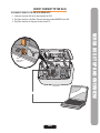
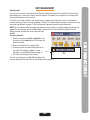
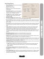
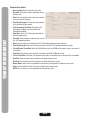
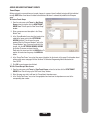
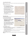
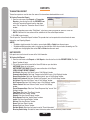
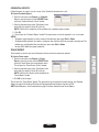
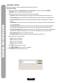
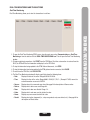
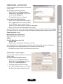
Versa XS
TM
Quick Start Guide
Versatile Access Control Programming Software
for EL25
TABLE OF CONTENTS
SENDING/RECEIVING DATA COMMUNICATIONS .25-29
Transfer Data . . . . . . . . . . . . . . . . . . . . . . . . . . . . . .25
Using Direct control . . . . . . . . . . . . . . . . . . . . . . . . .26
Real-Time Monitoring and Transactions . . . . . .27-28
Communications-Auto-Configure . . . . . . . . . . . . . .29
Communications-Custom Configure . . . . . . . . . . . .29
VERSA XS SETTINGS . . . . . . . . . . . . . . . . . . . . . .30-32
Preferences . . . . . . . . . . . . . . . . . . . . . . . . . . . .30-31
Passwords . . . . . . . . . . . . . . . . . . . . . . . . . . . . . . . .32
Exit Versa XS . . . . . . . . . . . . . . . . . . . . . . . . . . . . . .32
APPENDIX . . . . . . . . . . . . . . . . . . . . . . . . . . . . . . . . . .33
NOTES . . . . . . . . . . . . . . . . . . . . . . . . . . . . . . . . . .34-36
CONTACT & COPYRIGHT
INFORMATION . . . . . . . . . . . . . . . . . . . .BACK COVER
NOTE: This manual has basic information about the functions of Versa XS. If additional information is needed please
review the Versa XS Advanced Programming Manual located on the Versa XS CD
PAGE 1
TABLE OF CONTENTS
VERSA XS SET UP AND OVERVIEW . . . . . . . . . . . .2-5
About Versa XS . . . . . . . . . . . . . . . . . . . . . . . . . . . . .2
System Requirements . . . . . . . . . . . . . . . . . . . . . . .2
Direct Connect to the EL25 . . . . . . . . . . . . . . . . . . . .3
Installation . . . . . . . . . . . . . . . . . . . . . . . . . . . . . . . . .4
Starting Versa XS . . . . . . . . . . . . . . . . . . . . . . . . . . .4
Main Screen . . . . . . . . . . . . . . . . . . . . . . . . . . . . . . .5
Icons . . . . . . . . . . . . . . . . . . . . . . . . . . . . . . . . . . . . .6
UNIT MANAGEMENT . . . . . . . . . . . . . . . . . . . . . . . .7-15
Create a Unit . . . . . . . . . . . . . . . . . . . . . . . . . . . . . . .7
Unit Configuration . . . . . . . . . . . . . . . . . . . . . . . .8-14
Unit Status . . . . . . . . . . . . . . . . . . . . . . . . . . . . . . . .15
TENANT MANAGEMENT . . . . . . . . . . . . . . . . . . . .16-21
Adding a Tenant Record . . . . . . . . . . . . . . . . . . . . .16
Viewing Tenant Information . . . . . . . . . . . . . . . . . . .16
Tenant Information Window . . . . . . . . . . . . . . . .17-18
Tenant Groups . . . . . . . . . . . . . . . . . . . . . . . . . . . . .19
Directory Codes . . . . . . . . . . . . . . . . . . . . . . . . .10-21
Credential Bulk Loading . . . . . . . . . . . . . . . . . . . . .21
REPORTS . . . . . . . . . . . . . . . . . . . . . . . . . . . . . . .12-24
Transaction Reports . . . . . . . . . . . . . . . . . . . . . . . .22
Unit Reports . . . . . . . . . . . . . . . . . . . . . . . . . . . . . .22
Credential Reports . . . . . . . . . . . . . . . . . . . . . . . . .23
Tenant Reports . . . . . . . . . . . . . . . . . . . . . . . . . . . .23
Exporting Reports . . . . . . . . . . . . . . . . . . . . . . . . . .24
Printing Reports . . . . . . . . . . . . . . . . . . . . . . . . . . .24
VERSA XS SET UP AND OVERVIEW
ABOUT VERSA XS
VERSA XS SET UP AND OVERVIEW
Versa XS is a Windows®-based software application that allows you to use your personal computer to conveniently
manage tenant and unit data for one or more EL25 units. Versa XS uses a Microsoft Access® database (.MDB file) to
store information associated with the unit(s). With Versa XS’s Send Data features, this information can then be easily
transmitted(i.e., uploaded) to the unit(s) via modem or direct connection.
Versa XS also allows you to receive (i.e., download) data from EL25 units. This is a necessary feature because each
EL25 unit has its own database, and data added to the unit via the unit’s keypad or your touch-tone phone will not be
added to Versa XS’s database until it is received from the unit. It is important to keep both databases updated so there
is no mismatched data.
SYSTEM REQUIREMENTS
Your system must have Windows 98 or higher and the following:
NOTE: For databases having a large number of access codes (e.g., a combination of 1000 or more directory codes,
entry codes, cards, etc.), Chamberlain strongly suggests using the recommended hardware.
Microsoft Windows® 98 or ME users
Pentium 233-megahertz (MHZ) (Pentium II 400-megahertz (MHz) Recommended)
64 MB of available RAM (128 MB Recommended)
240 MB of hard disk space (300 MB Recommended)
Internet Explorer 5.0 and/or Shockwave Flash Player (version 5.0 or later)
Hayes-compatible modem connected to a COM port
CD ROM
800 X 600 Display Setting
Microsoft Windows® NT, 2000 or XP
Pentium 333-megahertz (MHz) (Pentium II 400-megahertz (MHz) Recommended)
128 MB of available RAM (256 MB Recommended)
240 MB of hard disk space (300 MB Recommended)
Internet Explorer 5.0 and/or Shockwave Flash Player (version 5.0 or later)
Hayes-compatible modem connected to a COM port
CD ROM
800 X 600 Display Setting
PAGE 2
DIRECT CONNECT TO THE EL25
TO CONNECT DIRECTLY TO THE EL25 USING A PC
1. Locate pin connector J301 on the main board of the EL25.
2. Plug 3 pin connector of the Direct Connect cable (part number 002B0731) into J301.
3. Plug 9 pin connector into 9 pin port located on your PC.
VERSA XS SET UP AND OVERVIEW
Direct Connect
Cable
J301
Direct Connect
Connector
PAGE 3
INSTALLATION
Important: Users cannot run Versa XS on a central server from remote workstations. All users must have Versa XS
installed on their local computer.
To Install Versa XS:
VERSA XS SET UP AND OVERVIEW
1. Start Windows®.
2. Place the Versa XS CD in the CD ROM drive. Versa XS will automatically start the installation process; follow the
on-screen prompts. If the installation process does not automatically start, continue with the instructions below.
3. From the taskbar, click Start >> Settings >> Control Panel.
4. From the Control Panel window, double-click on Add/Remove Programs.
5. From the Add/Remove Programs screen, click the Install/Uninstall tab or Add New Programs button (depending on
you operating system). Click Install or the CD or Floppy button.
6. Follow the on-screen prompts.
NOTE: Versa XS may prompt you to reboot your computer one or more times during the installation process. This is
required by Microsoft®. If after each reboot Versa XS does not automatically continue with the installation, double-click
on the setup.exe file in the Versa XS subdirectory.
You have completed the installation.
Starting Versa XS
From the Desktop (if a shortcut exists):
Double-click the Versa XS icon,
OR
From the Start Menu:
1. Click the Start button.
2. From the Start menu, select Programs >> Versa XS >> Versa XS.
If the Versa XS Password screen appears, enter password.
For information on enabling/disabling passwords, review the Versa XS software manual contained on the Versa XS CD.
NOTES:
• Versa XS is the default name of the program group and will appear unless you change the program group name
at installation.
• To create a shortcut to Versa XS, drag the Versa XS.exe file icon onto the desktop (see your Windows User Guide
for details).
• At startup, Versa XS will display the Main Screen. See Main Screen, page 5 for more information.
PAGE 4
MAIN SCREEN
Each time you activate the Versa XS program, the Main Screen will be displayed.
Main
Menu
Title Bar
Tool Bar
Unit List
Area
Parent
Window
Status
Bar
PAGE 5
VERSA XS SET UP AND OVERVIEW
The Main Screen is divided into different areas: Title Bar, Main Menu, Tool Bar, Unit List, Parent Window and Status Bar.
• Title Bar: Displays the name of the application Versa XS, followed by the currently used database path.
• Main Menu: Displays the names of the menus. Clicking a menu name displays a list of commands for accessing
Versa XS functions.
• Tool Bar: Displays icons that allow you to perform various Versa XS functions.
• Unit List: Displays the units stored in the current database.
• Parent Window: Displays windows currently in use (i.e. Tenant Information windows, New Unit windows, etc..)
• Status Bar: Displays helpful information for the window currently selected.
ICONS
VERSA XS SET UP AND OVERVIEW
Unit Management
New Unit: Used to create a
new unit.
Unit Configuration: Used to
access various unit setting
windows.
Settings: Used to
configure the unit settings.
Time Zones: Used to
set up time zones
(schedules).
Relays: Used to
open the time zones
window.
Devices: Used to define
and enable/disable devices
connected to the EL25.
Doors: Used to define
and enable/disable devices
connected to the EL25.
Alarms: Used to
enable/disable alarm
situations.
Unit Status: Used to display
selected unit's status.
Tenant Management
New Tenant: Used to create
a new tenant.
View Tenants: Used to display
tenant information.
View Tenant Groups: Used to
display tenant group information.
New Tenant Group: Used to
create a new tenant group.
New Directory Code: Used to
create a new directory code.
View Directory Codes: Used to
display all directory codes for a
selected unit.
Bulk Load Credentials: Used to
enter credentials (tags) into a
selected unit.
View Credentials: Used to
display credential (tag)
information.
Sending/Receiving Data Communications
Direct Control: Used to
give commands to
the EL25 unit via your PC.
Real Time Monitoring: Used to
monitor the EL25 unit.
Auto-Configuration: Used to
define connection details
automatically.
Custom Configurations: Used to
define connection details.
Transfer Data: Used to exchange
information between your PC
and the EL25.
Firmware Update: Used to
update firmware between
your PC and the EL25.
Reports: Used to access various
report windows
Unit Report: Used to create
spread sheets on unit activity.
Credential Report: Used to
create spread sheets that display
credential activity.
Transaction Report: Used to
create spread sheets that display
credential activity.
Tenant Report: Used to
create spread sheets that display
tenant activity.
Export: Used to convert
spread sheets created in
Versa XS to .exl or .txt formats.
Reports
Versa XS Commands
Password: Used to
enable/disable password
settings.
Save: Saves information
in currently selected
window.
Save All: Saves information
in all open windows.
Help Contents: Opens On-Line
Help.
Preferences: Used to define
Versa XS settings.
Screen Tip: Opens an information
box that displays the purpose of
the currently selected screen.
PAGE 6
Exit: Closes Versa XS.
UNIT MANAGEMENT
Creating a Unit
You may create a new unit at any time with Versa XS. Versa XS does not require that an actual EL25 unit be installed
before allowing you to add a new unit to the Versa XS database. This enables you to configure the unit’s settings and
add tenant data before the unit is installed.
PAGE 7
UNIT MANAGEMENT
If the EL25 unit is already installed, it may already have pre-loaded tenant and unit data. In that case, Chamberlain
recommends that you create a new unit and perform a “Receive All” command before you begin to enter or edit unit and
tenant data (see Mismatch on pages 57-58 of the Advanced Programming manual for more information).
NOTE: Versa XS contains default unit settings that allow you to quickly create a unit without entering data for each unit
property. You must, however, enter a Unit Name. When creating a new unit, review the default settings on the “Unit
Settings” windows to review them to see if they need to be
modified.
To Create a New Unit:
1. From the main menu select Unit >> New Unit or from
the tool bar, click the New Unit icon. This will open the
“New Unit” window.
2. Enter the Unit Name. This is a required field.
3. If necessary, modify any default settings data for the
unit on both “Unit Settings” windows. For more
Unit List
information, see Unit Settings Reference, page 11.
Unit
Unit
Name
Icon
4. Click OK to save changes to save the entry.
The unit’s icon will appear in the Unit List (left sidebar). You
may start adding tenant records to the unit (see Adding a Tenant, page 12.)
UNIT CONFIGURATION
Unit Settings Reference
The Unit Settings windows allow you to modify a unit
definition. It can be accessed by selecting Unit >>
Configure >> Settings from the main menu, or from the
tool bar click the Unit Configuration icon >> Settings.
UNIT MANAGEMENT
Unit Settings Reference
• Unit Name: Name that you will assign to a single
unit. This is a REQUIRED FIELD when creating a
new unit.
• Unit Type: N/A.
• Country: Select which country that the EL25 is
located in from the drop-down menu or enter
name.
• State/Prov.: Enter the state that the EL25 is located or select it from the drop-down menu.
• City: Enter the city that the EL25 is located in.
• Unit Password: Displays the unit’s current password. The unit will not allow you to program the system unless you
know the unit password. The password must have six digits (000000-999999).
• Description: Use this box to enter optional information about the unit.
• Unit No.: Up to seven (7) EL25 units can be installed on a single telephone line. Each unit must have a unique
number from 1 to 7. The unit number identifies each unit within a chain. Adding or removing EL25 units will require
the unit ID’s to be re-entered. Versa XS CANNOT change the unit number during programming. The Unit can ONLY
be changed at the unit’s keypad.
• Linked Unit Group: Select an existing group name or enter a new one.
• Connect Set: Allows you to select a pre-defined set of instructions that tells Versa XS how to connect with the unit.
A connect set can include instructions for direct connection (RS232 and COM port) or modem connection (modem
type, baud rate, and COM port). Connect sets are created when configuring your communications settings.
• PBX Digit: If a EL25 unit is connected to a PBX telephone system, it can be directed to dial a specified digit, pause
briefly (so the PBX can give the system an outside line) and then dial any 7-digit (or longer) telephone number that
has been programmed into the system.
• Rings Before Answer: Sets the number of rings before the system answers a remote call to program the EL unit.
Number can be between 0-15 (default: 5 rings). A value of 0 will NOT allow the EL25 to be programmed remotely.
• Phone No.: Enter the telephone number of the phone line currently connected to the EL25 unit.
• Override Answering Service: When enabled, Versa XS will override the answering service by dialing the line
attached to your unit, letting the phone ring the specified “Number of Rings”, and then hanging up. After a few
seconds, Versa XS will dial the same number again. The unit will immediately answer the second call.
• Number of Rings: Determines the number of rings allowed to connect to the unit when “Override Answering
Service” is enabled. Max. 9 rings.
• Retry Delay: Sets the length of time (in seconds) before Versa XS will retry to connect. When “Override Answering
Service” is enabled.
• Alternate Prefixes: When the homeowner or manager presses ## or *** on the resident phone, the unit will
disconnects from the telephone line and allow the person to send a Direct Command (##) or program the system
(***), to wait for commands. Some telephone companies offer special features that require the person to press a
preceding “#” or “*”.
• Restore Defaults: Resets the unit settings to their default values.
PAGE 8
Control Settings Reference
PAGE 9
UNIT MANAGEMENT
• Record Deactivation: Allows you to preset how long
the record will be active.
• None: Records never expire.
• Fixed: Allows you to set a date when records will
become inactive.
• System Generated: Allows you to set the number of
days (from the date the record was created) before it
becomes inactive (1-1000 days, default: 30).
• Talk Time: Sets the number of seconds the visitor is
allowed to talk with the tenant (15-250 seconds,
default: 60 seconds).
• Max Visitor Call Rings: Sets the number of rings
(1-9) the unit will allow before it cancels a visitor call to the residence (default: 5 rings).
• Directory Code: Sets the directory code length to 1 or 2 digits. Decreasing the number of digits may make longer
directory codes invalid. You will need to change the longer directory codes to fit the shorter directory code length
(default 2 digits).
• Entry Code: Sets the entry code length between 3 and 9 digits. Decreasing the number of digits may make longer
entry codes invalid. You will need to change the longer entry codes to fit the shorter entry code length (default 4
digits).
• Strikes and Out: Sets the maximum number of allowable keypad errors. The Strikes and Out feature prohibits
unauthorized persons from guessing an entry code or unit password. Anyone entering an entry code or unit
password will have a set number of times to correctly enter his/her code. Each time the code is entered
erroneously, it is a “strike”. After x number of “strikes”, the system will not allow code or password entry at the unit
for 3 minutes (default: 3 attempts). Note, the system will still allow program entry from other sources (i.e. remote
location).
• On Hook Threshold Count: Sensitivity of unit to detect On-Hook from resident phone.
• Off Hook Threshold Count: Sensitivity of unit to detect Off-Hook from resident phone.
• Speaker Level: The speaker enables the visitor to hear the resident at the unit. If the speaker’s volume is too low
or too high, you may adjust it accordingly. (1 is low; 10 is high; Mute = 0: Default = 5).
• Microphone Level: The microphone receives and transmits the sounds/speech from the unit to the resident. If the
sounds are indistinguishable, or the residents are having difficulty hearing the visitor’s speech, you may adjust the
microphone volume. (1 is low; 10 is high; Mute = 0: Default = 5).
• Enable Anti-Passback: The Anti-Passback feature deters someone from “passing back” his/her access code/card
to unauthorized individuals so they can gain entry into a restricted area.
1. Timed: Requires residents to wait a defined period of time before using the same access code (card, entry
code, etc) again on the same entry device (reader, keypad, etc.). Time can be set between 1-60 minutes
(default: 3 minutes).
2. True: Requires residents to exit before entering again (and vice versa).
• Reset Credentials @ Midnight: If True anti-passback is enabled, this setting will “reset” all access codes (cards)
at midnight.
• Access Granted Beeps: When enabled, the system will respond with short beeps when the unit grants a resident
entry. However, you can disable the sound if the beeping will be disruptive to others such as a resident living or
working nearby (default: Enabled).
UNIT MANAGEMENT
(Control Settings Reference Continued)
• Daylight Savings: When enabled, the system will automatically adjust the clock for daylight savings time
(default: Enabled).
• Auto Lock / Unlock Schedules: Enables Auto Lock/Unlock Schedules (a.k.a. Time Zones) for the unit. These
schedules allow you to create time periods to grant or deny access to a building or complex. Assign an
Auto Lock/Unlock Schedule to a door if you want the door to automatically unlock and lock on specific days and
times. For example, you can assign a schedule to a door so that it unlocks at 8AM and locks at 5PM (default:
Enabled). For more information about Time Zones (or other scheduling features) see Times Zones on pages 26-28
of this manual.
• Use Telephone Service: Enable this check box if the unit will use the telephone line. If this feature is disabled, the
unit will ignore its telephone line if it has one and all Telco features (e.g., call forwarding and call waiting) will be
disabled (default: Enabled).
• Direct Commands: With the Direct Command feature enabled, you can perform various functions (e.g., unlock a
door) from your phone. This feature is only available for a single family residence or a manager’s phone sharing a
phone line with the unit (default: Enabled).
• Voice Mail: If there is a voice mail system connected to a resident’s telephone line, the system allows the visitor to
dial an extension during a resident call. To use this feature, the visitor places a resident call, the voice mail system
answers the call, and then the visitor can dial an extension on the unit keypad. If disabled, the visitor will be
prohibited from dialing extensions during a resident call (default: Disabled).
• Enable Call Waiting: If your telephone is in use when the visitor attempts to contact you from the unit, you will
hear 2 short tones to signal that a visitor is attempting to call. You can press “2” on your phone to toggle between
the telephone call and the visitor. This feature is only available for a single-family residence or a manager’s phone
sharing a phone line with the EL25 (default: Enabled).
• Distinctive Ring: Changes how the resident phone rings when a visitor calls. This feature is ONLY available for a
single family residence.
• Ignore Facility Code: When enabled, Versa XS will ignore the facility code of cards and transmitters
(default: Enabled).
• Restore Defaults: Resets the unit settings to their default values.
Tenant Response Keys Reference
The Tenant Response Keys window allows you to define which keys on the EL25 unit will perform which functions from
the tenant/resident telephone.
• Open Door 1: Activates the relay group for Door 1.
• Open Door 2: Activates the relay group for Door 2.
• Open Door 3: Activates the relay group for Door 3.
• Open Door 4: Activates the relay group for Door 4.
• Toggle Call Waiting: Toggles between another
telephone call and the visitor.
• Extend Talk Time: Extends the amount of time you
may talk with a visitor.
• Hang Up: Hang up and deny access to the visitor.
PAGE 10
Devices
• Unit Timed Anti-Passback: Used to enable/disable and
define the keypad strike out time for the Timed AntiPassback feature.
• Unit True Anti-Passback: Used to enable/disable True
Anti-Passback and the Reset Credentials @ Midnight
features.
• Device Name: This field is used to give the device a
descriptive name. The Main Keypad may not be
renamed.
• Device Type: This field is used to define the type of
device that is attached to the EL25 unit.
• Anti-Passback: This field is used to define Anti-Passback settings for the selected device.
Relays
The EL25 unit must have all external access control device
options configured into it. You must tell the unit what is
wired to it and how you want the devices to behave. This
screen allows you to configure each input and outputs for
each relay.
• Relays: This area allows you to name and define
relay settings.
• Relay Groups: This area is used to define relay
groups.
• Automatic Sensors: This field is used to define
any automatic sensors you may have attached to
the EL25.
PAGE 11
UNIT MANAGEMENT
This window allows you to set up the devices attached to the EL25 unit.
• Device Configuration Wizard: Will open the Device
Configuration Wizard which allows you to define what
devices are attached to the EL25.
Time Zones
Time Zones (a.k.a. Schedules ) allow you to create time
periods to grant or deny access to a building or complex.
Time Zones may be assigned to access codes (e.g., entry
codes, cards, etc.) or doors. Time Zones are created and
edited using the Time Zone Screen.
• Number: Organizes the time zones into a numerical
format.
• Name: Used to define the Time Zone with a
descriptive name.
• Description: Allows you to enter a brief explanation
of the time zone.
• Segment Details: This area allows you to define the
settings of the selected time zone.
UNIT MANAGEMENT
Holidays
This feature enables you to program the EL25 with up to 16
holiday dates that replace existing schedules (e.g.,
auto-lock/unlock and card/code entry schedules) during the
defined date. Click here for a screen shot. For information on
defining holidays click here.
• Number: Organizes the time zones into a numerical
format.
• Holiday: Used to define the Holiday with a descriptive
name.
• Date: Used to define the date that the holiday is to take
place (i.e., January 1, 2005)
• Description: Used to enter a brief description of the
holiday.
PAGE 12
This window is used to define doors/entry ways that the EL25 will operate.
• Door Name: Used to define door/entry way name.
(i.e., front gate, pedestrian door, etc...)
• Main Keypad: This field defines what doors/entry ways
the Main Keypad will operate.
• Device 1: This field defines what doors/entry ways
Device 1 will operate.
• Device 2: This field defines what doors/entry ways
Device 2 will operate.
• Device 3: This field defines what doors/entry ways
Device 3 will operate.
• Device 4: This field defines what doors/entry ways
Device 4 will operate.
• Postal Lock: This field defines what doors/entry ways
the Postal Lock will operate.
• Activate Relay Group: Displays relay groups that are currently active for the selected door.
• Active Schedule: Displays any schedules that are active for the selected door.
• Auto Unlock Schedule: Displays any unlock schedules that are active for the selected door.
• Exit Device: Used define if an exit device is active for the selected door.
• Door Contact Sensor: Used to define any door contact sensors that are active for the selected door.
PAGE 13
UNIT MANAGEMENT
Doors
Alarms
This window is used to define alarms for the EL25.
• Door Held Open Alarm: Used to enable/disable door
held open alarm.
• Door Forced Open Alarm: Used to enable/disable the
door forced open alarm.
• Strikes and Out Alarm: Used to enable/disable the
strikes and out alarm.
• Door Contact Sensor: Used to define any door
contact sensors that are active for the selected door.
UNIT MANAGEMENT
Icons and Buttons
• Screen Tip Icon: The Screen Tip Icon provides you with a
description of the current open window.
• Save Button: Saves changes on the currently open screen.
• Close Button: Closes the window.
• Edit Button: Used to modify locked windows.
• Delete Button: Allows you to delete information from selected fields.
• Reset Button: Reverts information in the open window to default
values.
PAGE 14
• Updates Pending: Displays whether updates in Versa XS have been uploaded to the unit.
3. Click CLOSE when finished.
PAGE 15
UNIT MANAGEMENT
Unit Status
To View the Unit’s Status:
1. From the main menu select Unit >> Unit Status or
from the tool bar click the UNIT STATUS icon.
2. The unit status window displays the following
information:
• Unit Name: Displays the name of the unit
selected.
• Group: Displays the group the unit is associated
with.
• FID: Displays the FID number of the unit.
NOTE: A value of “Unknown” indicates Versa XS
has never communicated with the selected unit.
• Capacity Used:Displays the number of
codes/access credentials saved in the unit’s
memory
1. No. of Directory Codes: Displays the number or directory codes saved at Versa XS.
2. No. of Assigned Credentials and Tenant Entry Codes: Displays the number of access credentials
(cards, transmitters, entry codes, etc.) assigned to a tenant at Versa XS.
3. No. of Access Credentials: Displays the number of access credentials (cards, transmitters, entry codes,
etc.) currently saved and not assigned to a tenant at Versa XS.
• Definition Last Modified: Displays when Versa XS last received data from the unit.
• Unit Last Updated: Displays when the unit was last uploaded with new information.
• Firmware Updated Date: Displays when the firmware of the unit was updated.
TENANT MANAGEMENT
TENANT MANAGEMENT
Adding a Tenant Record
From the Unit List area, select the unit and/or unit group to
which the new tenant will be added.
1. From the main menu, select Tenant >> New Tenant,
or from the tool bar click the NEW TENANT icon. The
New Tenant screen will appear.
2. Enter all the necessary tenant data.
3. For reference information about the fields on the
Tenant Information screen, see Tenant Information
pages 13-14 in this manual.
4. Click OK to save changes when finished.
The tenant record will be added to all of the selected unit
or unit group.
Viewing Tenant Information
While viewing tenant information you may also edit the tenant’s information.
To View Tenant Information:
1. From the main menu select Tenant >> View Tenants or from the tool bar click the VIEW TENANTS icon. This will
bring up the Tenant Information window.
2. From the drop-down menu next to the “Last Name” field, select the tenant who’s information you wish to view.
3. Once you have reviewed/edited the tenant’s information click the SAVE ICON on the tool bar.
PAGE 16
TENANT INFORMATION WINDOW
The Tenant information Window is divided into 3 windows:
Tenant Info: Basic Information about the tenant (i.e. First and Last name, Car information etc.)
Access Details: Information about access control devices (transmitters, cards etc.) associated with the tenant.
Telephone Entry Details: Information about tenant’s directory code and time zone restrictions.
Tenant Info Window
•
•
•
•
•
• End Date: Enter date tenant record will no longer be
active.
• Car Type (User Defined field): Enter tenant’s vehicle type.
• Car Make (user defined field): Enter tenant’s vehicle make.
• License Plate (user defined field): Enter license plate number.
• Key Deposit (user defined field): Enter key deposit information.
• Photograph: Select image of tenant (JPEG, .bmp, and .gif format).
Access Details
• Tenant Group: Select tenant group information, if
applicable.
• Time Zones: Select the time zone restrictions (if any)
for the tenant on each door.
• Entry Code: Enter or modify tenant’s entry code.
• Access Credentials #1 and #2: Select tenant’s
access control devices using the select button.
PAGE 17
TENANT MANAGEMENT
•
•
•
•
Last Name: Enter tenant’s last name.
First Name: Enter tenant’s first name.
Middle Initial: Enter tenant’s middle initial.
Display Info: Shows how tenants name will appear in
transactions created by the EL25.
Address: Enter tenant’s address.
City: Enter tenant’s city.
State/Prov.: Enter tenant’s state or province.
“Active” Check Box: Check box if tenant’s record is
active, leave unchecked if tenant record is inactive.
Start Date: Enter date the tenant record will become
active.
TENANT MANAGEMENT
Telephone Entry Details
• Directory Code: Select tenant’s directory code.
• Phone No.: Enter phone number associated with the
directory code.
• Extn: Enter any extension that needs to be entered to
access the tenant’s telephone.
• Time Delay Seconds: Enter any time delay required
for the extension (0-30 seconds).
• “Call Forwarding” Check Box: Check box if Call
Forwarding is enabled, leave unchecked if Call
Forwarding is disabled.
• Time Zone: Select a Time Zone associated with the
Call Forwarding feature.
• Phone No.: Enter telephone number the unit is to call
in a Call Forwarding situation.
• Extn: Enter any extension associated with the Call Forwarding telephone number extension.
• Time Delay Seconds: Enter any time delay required to access the Call Forwarding telephone number.
• “Do Not Disturb” Check Box: Check the Do Not Disturb check box if DND will be enabled. Leave it unchecked if
it is disabled.
• Time Zone: Enter any time zone restriction associated with the Do Not Disturb function.
• “Active” Check Box: Check box if the telephone entry details are enabled, leave unchecked if they are disabled.
• Start Date: Enter start date that the telephone entry details become active.
• End Date: Enter end date when the telephone entry details will become inactive.
• Display Name: Select name to be displayed in transactions associated with the telephone entry details.
• Select: Select the Display Info of the tenants assigned to this directory code.
NOTE: Up to 15 tenants can be assigned to the same directory code.
PAGE 18
ADDING OR MODIFYING TENANT GROUPS
Tenant Groups
Setting up tenants in a group allows you to make changes to a group of tenant’s without having to edit their individual
records. NOTE: When a new tenant is added to the database, the tenant is automatically added to the “Everyone
group”.
PAGE 19
TENANT MANAGEMENT
To Create a Tenant Group:
1. From the main menu select Tenant >> New Tenant
Group or from the tool bar click the NEW TENANT
GROUP icon. This will open the “New Tenant Group”
window.
2. Enter a group name and description in the “Group
Details” area.
3. In the “Group Members” area select the tenants to be
added to the group and click the LEFT-FACING
ARROW (<) button. This will move the group
members from the “Everyone Members” area to the
“Group Members” area. If you want to add all of the
tenants, click the LEFT-FACING DOUBLE ARROW
(<<) button. To remove one tenant from the
Group,select the tenant and click the UNDO button. To
remove all tenants from the group, click UNDO ALL
button.
4. In the “Group Time Zones” area, select time zones (schedules) for the tenants in this group. For information about
setting up time zones see pages 26-28 of the Versa XS Advanced Programming Manual located on the
Versa XS CD.
5. Click OK to save changes when finished.
To Edit a Tenant Group’s Door Access:
1. From the main menu select Tenant >> View Tenant Groups or from the tool bar click the VIEW TENANT
GROUPS icon This will bring up the “Edit Tenant Group” window.
2. Select the group you wish to edit from the “Group Name” drop-down menu.
3. In the “Group Time Zones” area, select the appropriate time zone from the drop-down menu next to the
corresponding door number.
TENANT MANAGEMENT
Directory Codes
Directory codes are unique 1-2 digit codes that dial a corresponding telephone number in a complex, building, or
residence. The unit will dial a phone number that is associated with the directory code to contact a resident.
NOTE: Each Directory code can be assigned to a
maximum of 15 tenants.
To Add a New Directory Code:
1. From the main menu select Database >> New
Directory Code or from the tool bar click the NEW
DIRECTORY CODE icon. This will open the New
Directory Code window.
2. Enter directory code (1-2 digits)
3. Enter the phone number that the EL25 will call when
directory code is entered.
4. Enter an extension number (if required) the EL25 will
have to dial in order to contact the tenant.
5. Enter any time delay required for the extension (0-30 seconds).
6. Enable or disable do not disturb time zone (See Time Zones, page 21-22 of Owner’s Manual located on the Versa
XS CD.)
7. Enable or disable call forwarding (See Call Forwarding, page 44 of the Versa XS Owner’s Manual located on the
Versa XS CD for more information.)
8. Make directory code active or inactive.
9. Enter Start and End date (if required).
10. Change display name if necessary.
11. Click OK to save changes when finished.
To Modify or View Directory Codes:
1. From the main menu select Database >> View Directory Codes or from the tool bar click the VIEW DIRECTORY
CODES icon. This will open the View Directory Codes window.
2. From the drop-down menu select the directory code you wish to view or edit. If you need to edit the directory code,
click RENAME next to the directory code box. This will open the Change Directory Code window.
3. Change the directory code and Click OK to save changes.
4. Edit the phone number by selecting the Phone No. box
and typing over the existing phone number.
5. Enable or disable do not disturb schedule (see Time
Zones, page 26-28 for more information.)
6. Enable or disable call forwarding (see Call Forwarding,
page 43 of the Versa XS Advanced Programming
Manual for more information.)
7. Make directory code active or inactive.
8. Enter Start and End date (if required).
9. The “Assign To” field displays names that are associated
with the selected directory code. To select which name is
displayed. Click the SELECT button, this will open the
“Assign To” window, highlight the tenant name you want
to assign to the “Display Name” filed and click OK.
10. Click the SAVE ICON when finished .
PAGE 20
Assign a Directory Code to a Tenant
Credential Bulk Loading
This feature allows you to load a range of Transmitters or Cards to the unit’s record. The Transmitters or Cards should
be in numerical sequence without any gaps.
To Load a Group of Cards or Transmitters:
1. From the Main Menu select Database >> Credential
Bulk Loading or from the tool bar select BULK
LOAD CREDENTIALS ICON this will open the
Credential Bulk Loading window.
2. Select the type of access device from the drop-down
menu (i.e. transmitter, Sentex 30-bit card or Standard
26-bit card) from the Credential Bulk Loading window.
3. Enter in Access Details. (See Access Details,
page 30 of the Versa XS Advanced Programming
Manual.)
4. Click the SAVE icon when finished.
To View Credentials for a Tenant:
1. From the main menu select Database >> View Credentials or click the VIEW CREDENTIALS icon from the tool
bar. This will open the “View Credential” window.
2. Select the credential you wish to edit from the drop-down menu, or if you want to create a new credential, select
“<Add New>” from the drop-down menu.
3. Select the tenant that is to be associated with the credential from the drop down menu.
4. Click the SAVE icon when finished.
NOTE: Versa XS will attempt to assign the new credential as Credential #1 or #2, if both are full Versa XS will overwrite
Credential #1.
PAGE 21
TENANT MANAGEMENT
In order for a directory code to contact a tenant when it is entered, the directory code must be assigned in the tenant’s
record.
To assign a directory code to a tenant:
1. Select the desired unit from the Unit List area.
2. From the main menu select Tenant >> View Tenants
or click the VIEW TENANTS icon from the tool bar.
This will open the View Tenants window.
3. Select the desired tenant from the drop-down menu.
This will open the tenant’s record.
4. Select the “Telephone Entry Details” tab. This will
display the “Telephone Entry Details” window.
5. From the “Directory Code” drop-down menu select the
directory code to be assigned to the selected tenant.
If the number needs to be changed you may edit the
number on this window.
6. Click the SAVE icon from the tool bar.
REPORTS
TRANSACTION REPORT
REPORTS
Transaction reports are used to view all or some of the transactions downloaded from a unit.
To Create a Transaction Report:
1. From the main menu select Reports >> Transaction
Reports or from the tool bar click the REPORTS icon
and select Transaction Reports from the drop-down
menu. This will open the “Transaction Search Criteria”
window.
2. From the drop-down menu under “Field Name”, select which fields you would like Versa XS to filter for.
NOTE: If left blank ALL transactions will be available in the Transaction Report window.
3. Click OK to save changes.
This will open the “Transaction Reports” window. This spread sheet can be exported to various formats for more
information, see Exporting Reports.
NOTES:
• To delete a single transaction first select a row and select Edit >> Delete from the main menu.
• To delete multiple transactions select a starting row, then hold the <Shift> key and select the ending row. The
multiple rows are highlighted, then select Edit >> Delete from the main menu.
UNIT REPORTS
Unit reports are used to view all or some of the Unit Information.
To Create a Unit Report:
1. From the main menu select Reports >> Unit Report or from the tool bar click the REPORTS ICON. The “Unit
Report” window will open.
2. The text file created will be saved to the Versa XS folder on your hard drive.
UNIT NAME: Name of unit in report.
UNIT REPORT FILE NAME: Shows file name and location of Unit Report.
VERSA XS UNIT REPORT FORMAT:
Unit Details: Data from “Unit Details” area of “Unit Settings” window
Communication Details: Data from “Communication Details” area of “Unit Settings” window
Record Deactivation: Data from “Record Deactivation” area of “Unit Settings” window
Enable Anti-Passback: Data from “Enable Anti-Passback” area of “Unit Settings” window
Unit Values: Data from “Unit Values” area of “Unit Settings” window
Unit Features: Data from “Unit Features” area of “Unit Settings” window
Volume Control: Data from “Volume Control” area of “Unit Settings”
window
Tenant Response Keys: Data from “Tenant Response Keys” area of “Unit
Settings” window
Time Zones: Data from “Time Zones” window
Holidays: Data from “Holiday” window
Outputs: Data from “Inputs/Outputs” window
Relay Groups: Data from “Inputs/Outputs” window
Inputs: Data from “Inputs/Outputs” window
Devices: Data from “Devices” window
Doors: Data from “Doors” window
Alarms: Data from “Alarms” window
Resident Details: Data from first tenant record of “Tenant Information”
Directory Code Listing: Printable list format of directory codes from the “Directory Codes” window
PAGE 22
CREDENTIAL REPORTS
Credential reports are used to view all or some of the Credential Information from a unit.
To Create a Credential Report:
1. From the main menu select Reports >> Credential
Report or from the tool bar click the REPORTS icon
and select “Credential Search Criteria” window.
2. From the drop-down menu under “Field Name” select
which fields you would like Versa XS to filter for.
NOTE: If left black ALL credentials will be available in the “Credential Report” window.
3. Click OK.
4. This will open the “Credential Report” window. This spread sheet can then be exported to .txt. or .exl format.
NOTES:
• To delete a single credential first select a row and from the main menu select Edit >> Delete.
• To delete multiple credentials first select a starting row, then hold the <Shift> key and select an ending row. The
multiple rows are highlighted, then from the main menu select Edit >> Delete.
• You may ONLY delete unassigned credentials.
TENANT REPORT
PAGE 23
REPORTS
Tenant reports are used to view tenant information that may have been removed or updated.
To Create a Tenant report:
1. From the main menu select Reports >> Tenant
Report or from the tool bar click the REPORTS icon
and select Tenant Report from the drop-down menu.
This will open the “Tenant Search Criteria” window.
2. From the drop-down menu under “Field Name” select
which fields you would like Versa XS to filter for.
NOTE: If left black ALL tenants will be available in the
“Tenant Report” window.
3. Click OK to save changes.
This will open the “Tenant Report” window. This spread sheet can be exported to various formats, see Exporting
Reports on page 24 of the Versa XS Advanced Programming Manual located on the Versa XS CD.
NOTE: See Preferences, Grid Customization on page 31 for more information over Tenant Reports.
EXPORTING REPORTS
Versa XS allows you to export Transaction, Credential and Tenant Reports to two formats. Microsoft Excel (.xls) and
Delimited Text File (.txt). You must generate the report before it can be exported.
To Export a Report:
1. From the main menu select Reports >> Export or from the tool bar click the REPORTS ICON and select Export
from the drop-down menu. This will open the “Export Report” window.
2. Name the file and select a location to save the spreadsheet.
3. Click SAVE.
PRINTING REPORTS
REPORTS
When a report is in the parent window Versa XS allows you to print it.
To Print a Tenant/Transaction Report:
1. Open either tenant or transaction report.
2. From the main menu select File >> Print. The file will immediately be sent to your default printer.
3. If it is necessary to change any information when printing such as page layout, printer or paper size, select File >>
Page Setup from the main menu.
4. When changes have been made to the Page Setup, Click OK to save changes.
PAGE 24
SENDING/RECEIVING DATA
TRANSFER DATA
PAGE 25
SENDING/RECEIVING DATA
Versa XS software allows you to transfer data to and from the EL25 unit and your computer.
The Transfer Data window can be accessed by selecting Communications >> Transfer Data from the main menu or
click the TRANSFER DATA icon on the tool bar. The Transfer Data window will open.
The Transfer Data Screen:
• Start Button: Opens the port, awakens the modem, initializes the modem and gets your computer connected to
the EL25 unit.
• Stop Button: Stops the transmission of information between the EL25 unit and your computer.
• Launch Scheduler: Allows you to schedule tasks to execute the “Transfer Data” operation for the current unit at a
later, specified time.
• Edit Scheduler: Allows you to edit and view Versa XS related scheduled tasks.
• Configuration: If this box is checked, the Unit Configuration data (i.e., time zones, devices, doors, credentials,
etc.) is included during Send/Receive. Configuration data entails unit settings, time zones, inputs/outputs, devices,
doors and alarms.
• Tenant Info: If this box is checked, the data related to tenants, directory codes and credentials will be included
during Send/Receive.
• Historical Transactions: If this check box is checked historical transactions will be transmitted back to Versa XS.
Transaction data can be filtered by “Since Last Retrieval”, “All” or “Since Custom Date and Time”.
USING DIRECT CONTROL
SENDING/RECEIVING DATA
Direct Control allows you to send commands from Versa XS to the EL25 unit.
To Use Direct Control:
1. From the Main Menu select Communications >> Direct Control or from the tool bar click the DIRECT
CONTROL icon. This will open the Direct Control window.
2. Select which action you want the unit to do from the Unit Actions window.
• Cycle Door: Used to momentarily open the door/gate for a visitor without having the visitor initiate a call.
• Latch Door Open: Activates relay associated with door. Door remains open until given a command to close.
• Latch Door Closed: Deactivates relay associated with door. Door remains closed until given a command
to open.
• Release Door: If you release a door from a “Latch Door Open Until” command, the door’s relay will deactivate
(i.e., the door will close.)
• Latch Door Open Until: Activates the door’s relays until a specified time of day, until manually prompted to
deactivate with a Release Door command, or until a time zone (schedule) overrides to relock the door.
• Latch Door Closed Until: Deactivates the door’s relays until a specified time of day, until manually prompted to
deactivate with a Release Door command, or until a time zone (schedule) overrides to unlock the door.
• Set System Clock: Allows you to change the unit’s clock.
• Receive Unit Clock: Allows you to view the current clock settings from the EL25 unit.
3. Select which door the action will effect.
• Door 1: Factory set to Relay 1.
• Door 2: Factory set to Relay 2.
• Door 3: Factory set to Relay 3.
• Door 4: Factory set to Relay 4.
4. Click START button to connect to the unit.
5. Click SEND CHANGES button to enable the command.
6. Click STOP button to disconnect from the unit.
PAGE 26
REAL-TIME MONITORING AND TRANSACTIONS
Real Time Monitoring
Real Time Monitoring allows you to view the transactions in real time.
PAGE 27
SENDING/RECEIVING DATA
1. To open the Real Time Monitoring (RTM) screen, from the main menu select Communications >> Real Time
Monitoring or from the tool bar click the REAL TIME MONITORING icon. This will open the Real Time Monitoring
window.
2. To begin monitoring transactions, click START from the RTM Menu. Each time a transaction is received from the
EL25, the RTM will filter the information and display it on the RTM Grid.
3. To stop the information being updated to the RTM Grid and disconnect, click STOP.
4. To stop the information from being updated to the RTM grid and remain connected, click PAUSE.
5. To reset/clear the RTM Grid, click CLEAR RTM.
6. The Real Time Monitoring window will display a grid that shows the following items:
• Date:
Displays the date of the action. Range 01/01/01-12/31/99.
• Time:
Displays the time of the action. Range 00:00 - 23:59 (B, C, D, E ...) Example 17:35B, means the
second transaction occurred at 5:35PM.
• Source: Displays where the command came from. See page 24 for descriptions of Source codes.
• Device: Displays which device was used Range 0-4.
• Door:
Displays which door was affected. Range 1-4.
• Code:
Displays which code was used to activate the door.
• Name:
Displays any name associated with the code.
• Result:
Displays what action happened (i.e., entry was granted, entry was denied, etc.). See page 28 for
descriptions of Result codes.
Source Codes
UNKN
CARD
RCVR
CODE
AUTO
CALL
DCMD
DIR
=
=
=
=
=
=
=
=
Unknown
Card reader module
RF module
Entry code
Automatic sensor
Residence call
Direct command
Directory code
INVLD UNKNOWN
CLEAR AJAR
ALARM AJAR
CLEAR FORCED
ALARM FORCED
CLEAR STK&OUT
ALARM STK&OUT
DENIED APBACK
=
=
=
=
=
=
=
=
DENIED DND
DENID IN PROG
=
=
DENI AUTO ANS
=
DENI INC RING
=
DENI IN RTMDM
=
DENI IN RTLCL
=
DNI ROFHK NCW
=
DNI ROFHK RTM
=
DNI RES OFFHK
=
DNI MU PROGM
=
DENID VIS HNG
DENID RES HNG
=
=
Invalid unknown
Clear door held open alarm
Door held open alarm
Clear door forced alarm
Door forced alarm
Clear strikes & out alarm
Strikes & out alarm
Denied code due to
anti-passback violation
Denied code due to DND
Denied visitor due to unit in
program mode
Denied visitor due to unit in
multi-unit chain auto answers
line
Denied visitor due to incoming
ring at unit
Denied directory code due to
unit in RMT mode remotely
through Telco side
Denied visitor due to
residence in RTM mode
Denied visitor due to
residence phone off-hook and
call waiting is disabled
Denied visitor, residence offhook and in RTM mode
Denied visitor, residence
off-hook and in RTM mode
Denied code, unit in multi-unit
chain is in program mode
Visitor canceled call
Residence hung up on
visitor call
DSC
PSTP
REX
SCHD
DOOR
PSWD
=
=
=
=
=
Door contact sensor
Program step
Request to exit input
Auto unlock/lock schedule
Postal input or door latch
release
= Enter/exit program mode at unit
SENDING/RECEIVING DATA
Result Codes
DENI TNAT HNG
= Directory call to tenant hung up
on visitor call
DENI RING EXP
= Visitor call rings exceeded
DENIED INACTV
= Denied code, code is inactive
DENIED INVRF
= Denied unknown transmitter
presented at unit
DENIED INVCDE
= Denied unknown entry code
presented to unit
DENIED INVCRD
= Denied unknown card
presented to unit
DNI INVCRDTPE
= Denied invalid card type
presented to unit
DENIED TALKTM
= Talk time expired for call
DENIED TMZONE = Denied code due to time zone
LATCH CLOSED
= Latch expired
LATCH OPEN
= Latch held open
LATCH RELEASE = Latch released
DENIED DR INA
= Denied code, door inactive
GRANTED
= Granted code access
GRANTED POSTL = Granted access via postal lock
input
GRANTED REX
= Granted access via REX input
PS CYCLE RELY
= Cycled relay through program
step
SCHED LOCK
= Auto schedule has locked
SCHED UNLOCK
= Auto schedule has unlocked
DENIED PRGMNG = Denied code due to unit in
program mode
UNIT RESTART
= Unit restarted
GRANTED PASSWD = Enter program mode
DENIED PASSWD = Invalid password to enter
programming mode
EXIT PROGMIN
= Exiting programming mode
PAGE 28
COMMUNICATIONS - AUTO CONFIGURE
Communications - Custom Configure
If you are using Versa XS for the first time, select the “Auto
Configure” option.
Opening the “Modem Configuration” Screen:
1. From the menu bar select Communications >>
Connect Sets >> Custom Configure, or from the
tool bar click the Custom Configure icon.
2. The Modem Configuration Screen will appear.
3. In the Modem Configuration Screen you can Create a
New Connect Set or Edit an Existing Connect Set.
PAGE 29
SENDING/RECEIVING DATA
If you are using Versa XS for the first time, select the “Auto
Configure” option.
To Auto Configure your Communications:
1. From the menu bar, select Communications >>
Connect Sets >> Auto Configure, or From the tool
bar click the Auto Configure icon.
2. The “Auto Configuration” screen will appear.
Versa XS will Perform the Following Tasks:
1. Search for each COM port and identify any modems.
2. Create a connect set for Direct Connection (RS232)
on each COM port. If you are unsure whether your
system is set up for a direct connection, contact your installing dealer.
3. Create a connect set for each modem (default will be 14.4 baud).
You may review the specifics of each connect set by scrolling down the top pane of connect set data. For an explanation
of the Connect Set specifics, see page 45 of the Versa XS Advanced Programming Manual located on the Versa XS CD.
Connect Type: Modem or Direct
Modem Speed or Direct Connection Port
Modem Type (Modem Connections Only)
COM Port
Baud Rate (Modem Connections Only)
Example: 14400
Displays modem’s baud speed. The default speed is 14.4 kbps.
In the “Connect Sets” pane, select one or more connect sets to save. To select multiple connect sets, hold down the
[Ctrl] or [Shift] keys on your computer keyboard and click the connect sets you wish to save.
4. Click OK to save changes. This will open the Modem Connection screen.
VERSA XS SETTINGS
PREFERENCES
Use the Preferences screen to edit various configuration options. Some of the options include editing the number of
retries when Versa XS fails to connect to a unit, 12 or 24-hour format, database merge option, and default file location
when backing up or restoring the database. Refer to one of the subtopics below for more information on the screen’s
tabs. To access the Preferences window select Tools >> Preferences from the main menu or click the Preferences
icon from the tool bar.
VERSA XS SETTINGS
General
Scheduler: Specify the number of connections Versa XS
will attempt during the scheduled data transfer. The
Scheduler allows you to program Versa XS to communicate
with the unit at a later time. You can specify the number of
attempts that should be tried before the Scheduler quits.
Before the Scheduler tries another attempt, it waits a
certain amount of time.You can specify the number of
minutes the Scheduler will wait between attempts. The
Scheduler will not wait for the first attempt.
Backup/Restore: This area allows you to assign the default
location where your Versa XS database will reside after you
back up or restore it.
To assign the default location: Enter the directory path
into the “Default File Location” box. Example: C:\Versa XS
Backups) Or click the BROWSE button to select the path.
Click OK to save changes to save any changes.
Database Options
When Versa XS receives data from a unit, the data from both
databases will merge. Sometimes conflicts will occur with the
merging of the data. The Database Options feature (also
referred to as “Merge Options”) allows you to specify how
conflicts between unit data and Versa XS data are resolved
during a merge.
Conflicts may arise when you consolidate data received from the unit with the data already stored in the Versa XS
database.
Example: A phone number associated with a directory code in the database may be different than a phone number
stored in the unit.
In the Database Options screen you can select how the database will handle such conflicts:
• Unit takes precedence: If this box is checked, whenever a conflict arises the Unit’s data is copied and saved over
the PC’s data.
• PC take precedence: If this box is checked, whenever a conflict is encountered the Unit’s data is ignored leaving
the PC’s data intact.
• Clear database and copy Unit’s image: If this box is checked, when a conflict is encountered the entire PC
database for the selected unit is cleared out and an exact copy of the Unit’s data is saved over to the PC
database.
Click OK to save changes to save any changes.
PAGE 30
User Defined Fields
Trace Log
Allows the Trace Log information to be saved.
To Save Trace Log Information:
1. Click the box next to ON.
2. Select Overwrite Existing File, to save over existing file, or
Append to Existing File, to add to existing file.
3. Enter the default file path or click BROWSE to select a
path.
4. Click OK to save changes.
NOTE: The Trace Log file name is “VersaXS.log”. Use caution if “Append to Existing File” is select .
Grid Customization
Allows you to select which fields are present in the Tenant Search Results or the Tenant Bulk Changes window.
To edit the Tenant Search Results or Tenant Bulk Update windows:
Select Tenant Search or Tenant Bulk Update from Select Grid
drop-down menu.
If you do not want an Item to display on the grid, highlight the
item in the Visible Columns window, and click LEFT facing
arrow. To add an item to the grid, highlight the item in the
Hidden Columns window, and click RIGHT facing arrow. To
remove all of the items to display click the DOUBLE-LEFT
facing arrows. To add all of the Hidden Columns click the
DOUBLE-RIGHT facing arrows. To change an items position on
the Grid, highlight the item and click the UP or DOWN arrows
next to the Visible Columns box.
Click OK to save changes.
PAGE 31
VERSA XS SETTINGS
User-defined fields allow you to track additional information
about each tenant on the Tenant Information screen for a unit or
linked unit group. Versa XS provides four user-defined fields. You
can specify the field captions as they will appear on the Tenant
Information screen.
Examples:
You create the field caption “Car Type”. You can then enter
the current tenant’s car in the field’s box (e.g., Blue
Mercedes) on the Tenant Information screen. You create
another field caption “Elderly”. You can then enter “Yes” or
“No” in the field’s box on the Tenant Information screen. You create another field caption “Years as Tenant”. You can
then enter the number of the years the current tenant has occupied the building in the field’s box on the Tenant
Information screen.
NOTE: If you change the captions for a Linked Unit Group, all units within the group will be affected.
To edit the user-defined field captions for a unit or unit group:
1. Select the Unit or Linked Unit Group radio button.
2. From the Unit/Linked Group Name drop-down box, select the unit or unit group that will be affected.
3. Enter the new caption(s) into the Field boxes.
4. Click OK to save changes.
PASSWORDS
Versa XS passwords can range in length from 1 to 10
characters or numbers (alphanumeric).
When Versa XS prompts you for a password, you must
enter it to start the application. If you don’t know your
password or it doesn’t work, check with your system
administrator (or the person who assigned it).
NOTE: The Versa XS password should not be confused
with the Unit password. The Versa XS password is used to
grant or deny access to the software. The Unit password is
used to access the EL25 unit for programming. For more
information on setting the Unit password, see Unit
Configuration page 8.
VERSA XS SETTINGS
To Set a Versa XS Password:
1. From the menu bar, select Tools >> Password OR from the tool bar click the Password icon.
2. The Set Password screen will appear. At the Set Password screen, enable the “Required” check box.
3. Enter the password into the “Password” and “Verify Password” text boxes.
4. Click OK to save changes.
To Remove the Versa XS Password:
1. At the Set Password screen, disable the “Required” check box.
2. Click OK to save changes.
NOTES:
• For security, entries are displayed as asterisks (*) instead of letters.
• ONLY alpha characters and numbers may be used.
• The password is case sensitive.
• After three unsuccessful password attempts, Versa XS will quit.
EXITING VERSA XS
To exit Versa XS select File >> Exit from the main menu or click the EXIT icon from the tool bar. Versa XS will prompt
you to ensure you wish to exit Versa XS. Click YES to exit.
PAGE 32
PAGE 33
APPENDIX
APPENDIX
Alarms . . . . . . . . . . . . . . . . . . . . . . . . . . . . . . . . . . . . . . . . . . . . . . . . . . . . . . . . . . . . . . . . . . . . . . . . . . . . . . . . . . . 14
Communications . . . . . . . . . . . . . . . . . . . . . . . . . . . . . . . . . . . . . . . . . . . . . . . . . . . . . . . . . . . . . . . . . . . . . . . . . . . 29
Control Settings . . . . . . . . . . . . . . . . . . . . . . . . . . . . . . . . . . . . . . . . . . . . . . . . . . . . . . . . . . . . . . . . . . . . . . . . . . 9-10
Devices. . . . . . . . . . . . . . . . . . . . . . . . . . . . . . . . . . . . . . . . . . . . . . . . . . . . . . . . . . . . . . . . . . . . . . . . . . . . . . . . . . . 11
Direct Connect. . . . . . . . . . . . . . . . . . . . . . . . . . . . . . . . . . . . . . . . . . . . . . . . . . . . . . . . . . . . . . . . . . . . . . . . . . . . . . 3
Direct Control . . . . . . . . . . . . . . . . . . . . . . . . . . . . . . . . . . . . . . . . . . . . . . . . . . . . . . . . . . . . . . . . . . . . . . . . . . . . . 26
Directory Codes . . . . . . . . . . . . . . . . . . . . . . . . . . . . . . . . . . . . . . . . . . . . . . . . . . . . . . . . . . . . . . . . . . . . . . . . . 20-21
Doors . . . . . . . . . . . . . . . . . . . . . . . . . . . . . . . . . . . . . . . . . . . . . . . . . . . . . . . . . . . . . . . . . . . . . . . . . . . . . . . . . . . 13
Holidays . . . . . . . . . . . . . . . . . . . . . . . . . . . . . . . . . . . . . . . . . . . . . . . . . . . . . . . . . . . . . . . . . . . . . . . . . . . . . . . . . . 12
Icons . . . . . . . . . . . . . . . . . . . . . . . . . . . . . . . . . . . . . . . . . . . . . . . . . . . . . . . . . . . . . . . . . . . . . . . . . . . . . . . . . . . . 6
Installation . . . . . . . . . . . . . . . . . . . . . . . . . . . . . . . . . . . . . . . . . . . . . . . . . . . . . . . . . . . . . . . . . . . . . . . . . . . . . . . . . 4
Password . . . . . . . . . . . . . . . . . . . . . . . . . . . . . . . . . . . . . . . . . . . . . . . . . . . . . . . . . . . . . . . . . . . . . . . . . . . . . . . . . 32
Real Time monitoring . . . . . . . . . . . . . . . . . . . . . . . . . . . . . . . . . . . . . . . . . . . . . . . . . . . . . . . . . . . . . . . . . . . . . . . 27
Relays . . . . . . . . . . . . . . . . . . . . . . . . . . . . . . . . . . . . . . . . . . . . . . . . . . . . . . . . . . . . . . . . . . . . . . . . . . . . . . . . . . . 11
Reports . . . . . . . . . . . . . . . . . . . . . . . . . . . . . . . . . . . . . . . . . . . . . . . . . . . . . . . . . . . . . . . . . . . . . . . . . . . . . . . . 22-24
System Codes . . . . . . . . . . . . . . . . . . . . . . . . . . . . . . . . . . . . . . . . . . . . . . . . . . . . . . . . . . . . . . . . . . . . . . . . . . . . . 28
System Requirements . . . . . . . . . . . . . . . . . . . . . . . . . . . . . . . . . . . . . . . . . . . . . . . . . . . . . . . . . . . . . . . . . . . . . . . 2
Tenant
- Management . . . . . . . . . . . . . . . . . . . . . . . . . . . . . . . . . . . . . . . . . . . . . . . . . . . . . . . . . . . . . . . . . . . . . . 16-18
- Groups . . . . . . . . . . . . . . . . . . . . . . . . . . . . . . . . . . . . . . . . . . . . . . . . . . . . . . . . . . . . . . . . . . . . . . . . . . . . . 19
Time Zones . . . . . . . . . . . . . . . . . . . . . . . . . . . . . . . . . . . . . . . . . . . . . . . . . . . . . . . . . . . . . . . . . . . . . . . . . . . . . . . 12
Transfer Data . . . . . . . . . . . . . . . . . . . . . . . . . . . . . . . . . . . . . . . . . . . . . . . . . . . . . . . . . . . . . . . . . . . . . . . . . . . . . . 25
Unit
- Configuration. . . . . . . . . . . . . . . . . . . . . . . . . . . . . . . . . . . . . . . . . . . . . . . . . . . . . . . . . . . . . . . . . . . . . . . . . . 8
- Management . . . . . . . . . . . . . . . . . . . . . . . . . . . . . . . . . . . . . . . . . . . . . . . . . . . . . . . . . . . . . . . . . . . . . . . . . . 7
- Status . . . . . . . . . . . . . . . . . . . . . . . . . . . . . . . . . . . . . . . . . . . . . . . . . . . . . . . . . . . . . . . . . . . . . . . . . . . . . . 15
Versa XS
- About. . . . . . . . . . . . . . . . . . . . . . . . . . . . . . . . . . . . . . . . . . . . . . . . . . . . . . . . . . . . . . . . . . . . . . . . . . . . . . . . 2
- Settings . . . . . . . . . . . . . . . . . . . . . . . . . . . . . . . . . . . . . . . . . . . . . . . . . . . . . . . . . . . . . . . . . . . . . . . . . . 30-31
- Starting . . . . . . . . . . . . . . . . . . . . . . . . . . . . . . . . . . . . . . . . . . . . . . . . . . . . . . . . . . . . . . . . . . . . . . . . . . . . . . 4
NOTES
NOTES
PAGE 34
NOTES
NOTES
PAGE 35
NOTES
NOTES
PAGE 36
CONTACT AND COPYRIGHT INFORMATION
Visit us on the web at www.chamberlain.com.
For Technical Support, please contact your local Chamberlain dealer.
This document is protected by copyright and may not be copied or adapted without the prior written
consent of Chamberlain. This document contains information proprietary to Chamberlain and such
information may not be distributed without the prior written consent of Chamberlain. The software and
firmware included in the Chamberlain product as they relate to this document are also protected by
copyright and contain information proprietary to Chamberlain.
Microsoft and Windows are registered trademarks of Microsoft Corporation. Other brands and their
products are trademarks or registered trademarks of their respective holders and should be noted as
such.
114A2981B
© 2004 THE CHAMBERLAIN GROUP
ALL RIGHTS RESERVED