1
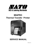
Unit 1: Introduction
LED’s
SATO XL Printer
ERROR
ON LINE
START
/STOP
FEED
LCD Display
CUTTER
ON/OFF
EJECT
MEDIA TYPE
Function Keys
Figure 1-2b, Control Features
CONNECTION PORTS
AC Power Input
Interface Port
Connector permits 115V, 50/60 Hz supply via supplied cord.
Connector for interface harness. Must be connected for the printer to
be operational. Acceptable interface types are:
•
•
•
•
•
Ext. Interface Port
Memory Card Slot
RS232C Serial I/F Module, DB-25
Parallel
Universal Serial Bus Adapter
Ethernet 10/100 BaseT I/F Module
RS422/485 I/F Module, DB-9
Connector for external control of print cycle. Also supplies power for
optional accessories - AMP 57-60140
Slot for the insertion of optional PCMCIA Memory Card
M em ory Card S lot
Serial Interface Port
Interface Port
Accessory P ort
Figure 1-3, Connection Ports
SATO XL400-410e Operator Manual
PN 9001135C
Page 1-5