1
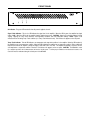
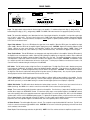
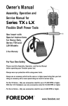
TM
MPA250
Multi-Purpose Amplifier
Operation Manual
Biamp Systems, 10074 S.W. Arctic Drive, Beaverton, Oregon 97005 USA
an affiliate of Rauland-Borg Corp.
(503) 641-7287
www.biamp.com
blank
print update
Spetember 16, 2002
MPA250
INTRODUCTION
TABLE OF CONTENTS
Front Panel
pg. 2
Rear Panel
pg. 3
Specifications
pg. 4
MPA250 single-channel, multi-purpose amplifiers deliver a full 250 Watts of power into
direct or distributed speaker systems. The MPA250 is designed for reliable service in
permanent installations, and comes complete with short-circuit and thermal protection,
including front/rear panel indicators and automatic reset. Plug-in barrier strip input and
screw terminal outputs provide trouble-free, dependable connections. MPA250
amplifiers are UL listed and carry Biamp's five-year warranty.
Warranty
MPA250 features include:
250 watts at all outputs (4W direct & transformer)
internal transformer (8W, 70V, 25V, & 25V-CT outputs)
signal/peak & temp/fault indicators on front & rear panels
balanced/unbalanced input selector on rear panel
level control & input sensitivity selector on rear panel
high-pass filter selector on rear panel (12dB/oct. @ 125Hz)
input on plug-in barrier - outputs on screw terminals
complete speaker, short-circuit, & thermal protection
variable speed fan (quiet, reliable - no filter maintenance)
incorporates AES recommended grounding practices
covered by Biamp Systems' five-year warranty
UL / C-UL listed
IMPORTANT SAFETY INFORMATION
Read these instructions.
Do not install near any heat sources such as
radiators, heat registers, stoves, or other apparatus
(including amplifiers) that produce heat.
Keep these instructions.
Heed all warnings.
Do not defeat the safety purpose of the polarized or
grounding-type plug. A polarized plug has two
blades with one wider than the other. A grounding
type plug has two blades and a third grounding
prong. The wide blade or the third prong are
provided for your safety. When the provided plug
does not fit into your outlet, consult an electrician for
replacement of the obsolete outlet.
Follow all instructions.
Do not use this apparatus near water.
Clean only with a dry cloth.
Do not block any of the ventilation openings.
Protect the power cord from being walked on or
pinched particularly at plugs, convenience
receptacles, and the point where they exit from the
apparatus.
Install in accordance with the manufacturers
instructions.
WARNING - To reduce the risk of electric shock,
do not expose this apparatus to rain or moisture.
Refer all servicing to qualified service personnel.
Servicing is required when the apparatus has been
damaged in any way, such as power-supply cord or
plug is damaged, liquid has been spilled or objects
have fallen into the apparatus, the apparatus has
been exposed to rain or moisture, does not operate
normally, or has been dropped.
Unplug this apparatus during lightning storms or
when unused for long periods of time.
Apparatus shall not be exposed to dripping or
splashing and no objects filled with liquids, such as
vases, shall be placed on the apparatus.
Explanation of safety related markings and symbols which appear on the outside of the apparatus.
Lightning Bolt: Hazardous Live voltages present when this unit is in operation. Do not touch terminals
marked with this symbol while the unit is connected to live power.
Exclamation Point: Replace components (i.e. fuses) only with the values specified by the
manufacturer. Failure to do so will compromise safe operation of this unit.
1
FRONT PANEL
MPA250
on
signal
peak
temp
fault
On Indicator: This green LED remains lit when AC power is applied to the unit.
Signal / Peak Indicator: This 2-color LED indicates the signal level for the amplifier. When the LED is green, the amplifier has signal
(above -30dB). When the LED is red, the amplifier signal is clipping (max. power). CAUTION: Signal levels should be adjusted to avoid
clipping. Clipping can cause severe distortion, over-temperature conditions, and even loudspeaker damage. NOTE: Signal / Peak
indicators will turn off during Temp / Fault conditions (see Temp / Fault Indicators below). This indicator also appears on the rear panel.
Temp / Fault Indicator: This red LED indicates over-temperature and output fault conditions for the amplifier. When the LED remains lit,
the amplifier has an over-temperature condition. When the LED is flashing, the amplifier has an output fault condition. Either condition will
temporarily de-activate the amplifier, causing the Signal / Peak LED to turn off as well. The amplifier will attempt to self-reset once the
over-temperature or output fault condition is resolved. This indicator also appears on the rear panel. CAUTION: The MPA250 is cooled
by a variable speed fan, which exhausts warm air from the left side panel. To allow proper ventilation, an un-obstructed clearance of at
least 0.75" must be maintained along the left side panel of the MPA250.
2
REAR PANEL
MPA250
CAUTION
US
RISK OF ELECTRICAL SHOCK.
DO NOT OPEN.
BIAMP SYSTEMS
an affiliate of Rauland Borg Corp.
MADE IN U.S.A.
~
direct
output
xfmr output
FUSE
8Ω
70V
25V
25V
CT
COM
OUT
XFMR
INPUT
4Ω
GND
signal / peak
Class 2 Wiring
CAUTION:
Risk of fire replace fuse only
with same type
6 A 250 V
FUSE
O
120V
60Hz
900 Watts
temp / fault
R
52SJ
UNBAL
775mV
OFF
UL
LISTED
BAL
300mV
HPF
C
level
input
Input: This plug-in barrier strip provides the line-level input to the amplifier. For unbalanced input, wire high (+) and ground ( ). For
balanced input, wire high (+), low (-), and ground ( ). NOTE: The UNBAL / BAL switch must be in the appropriate position (see below).
Level: This screw-driver adjustable control determines the level of input signals allowed into the amplifier. Level provides a gain range
from 'off' (min.) to 'unity' (max.). The Level control is factory set for -20dB of gain, which will produce maximum output power with input
signal peaks of +20dBu. For best performance, first adjust the source signals for optimum (maximum) levels, then adjust the amplifier
Level control for the desired volume.
Signal / Peak Indicator: This 2-color LED indicates the signal level for the amplifier. When the LED is green, the amplifier has signal
(above -30dB). When the LED is red, the amplifier signal is clipping (max. power). CAUTION: Signal levels should be adjusted to avoid
clipping. Clipping can cause severe distortion, over-temperature conditions, and even loudspeaker damage. NOTE: Signal / Peak
indicators will turn off during Temp / Fault conditions (see Temp / Fault Indicators below). This indicator also appears on the front panel.
Temp / Fault Indicator: This red LED indicates over-temperature and output fault conditions for the amplifier. When the LED remains lit,
the amplifier has an over-temperature condition. When the LED is flashing, the amplifier has an output fault condition. Either condition will
temporarily de-activate the amplifier, causing the Signal / Peak LED to turn off as well. The amplifier will attempt to self-reset once the
over-temperature or output fault condition is resolved. This indicator also appears on the front panel. CAUTION: The MPA250 is cooled
by a variable speed fan, which exhausts warm air from the left side panel. To allow proper ventilation, an un-obstructed clearance of at
least 0.75" must be maintained along the left side panel of the MPA250.
HPF Switch: This DIP switch provides a High-Pass Filter for the amplifier input. The High-Pass Filter is used to eliminate unnecessary
lower frequencies (12dB/octave @ 125Hz) for speech and distributed speaker applications. From the factory, the High-Pass Filter is
enabled (switch down). To disable the High-Pass Filter, move the switch to the up position. CAUTION: To avoid output fault conditions,
the High-Pass Filter must be enabled when driving 25/70 Volt speaker systems (see Output below). Also, any other system equalization
affecting frequencies below 125 Hz should remain flat or be used as cut-only.
775mV / 300mV Switch: This DIP switch selects 0.775Vrms (-0dBu) or 0.3Vrms (-8dBu) as input sensitivity for the amplifier. From the
factory, input sensitivity is set for 775mV (switch up). Use the 775mV setting for 'professional' line-level input signals (such as from an
audio mixer or processor), or use the 300mV setting for 'consumer' line-level signals (such as from a CD player or tape deck).
UNBAL / BAL Switch: This DIP switch selects unbalanced or balanced input connection. From the factory, input connection is set for
UNBAL (switch up). Use UNBAL for 2-conductor connections, and use BAL for 3-wire connections (see Input above).
Output: These screw terminals provide the speaker outputs from the amplifier. From the factory, a jumper wire is installed from the 4Ω
terminal (direct output) to the XFMR INPUT terminal. For transformer (xfmr) output, connect speaker negative to the COM OUT terminal,
and connect speaker positive to the appropriate transformer output terminal (8Ω for an 8 ohm speaker load; 70V for a 70 Volt distributed
speaker system; 25V for a 25 Volt distributed speaker system). For 'balanced' 25V speaker systems, connections are the same as above,
plus a ground connection (center-tap) made to the 25V CT terminal. For direct output from the amplifier, first remove the factory installed
jumper wire, then connect speaker negative to the GND terminal, and connect speaker positive to the 4Ω terminal.
AC Power Entrance: The switch applies AC power to the unit. The receptacle accepts the detachable AC Power Cord. The AC Power
Cord is for connection to three-prong grounded AC outlets. CAUTION: Do not remove or defeat the ground prong on the AC Power Cord,
as this constitutes a shock hazard.
Fuse: Replace Fuse with same type and value only (6 A 250 V). NOTE: If the Fuse continues to blow, the amplifier may require service.
3
SPECIFICATIONS
Continuous Power (4 ohm direct & transformer outputs):
250 watts
Signal-to-Noise Ratio (20Hz~20kHz):
referenced to 250 watts into 4 ohm direct output
> 90dB
Total Harmonic Distortion:
20Hz~20kHz @ 250 watts into 4 ohm direct output
< 0.2%
100Hz~15kHz @ 250 watts at transformer outputs
< 1.0%
Intermodulation Distortion (SMPTE):
< 0.35%
Frequency Response (20Hz~20kHz):
+0/-1dB
Input Impedance:
balanced
20k ohms
unbalanced
10k ohms
Input Sensitivity (selectable):
775mV / 300mV
Power Requirements:
120VAC @ 60Hz
Power Consumption:
900 watts
Dimensions (H x W x D):
3.5" x 19" x 8.5" (89 x 483 x 216mm)
Weight:
23 lbs. (10.5kg)
6
WARRANTY
BIAMP SYSTEMS IS PLEASED TO EXTEND THE FOLLOWING 5-YEAR
LIMITED WARRANTY TO THE ORIGINAL PURCHASER OF THE
PROFESSIONAL SOUND EQUIPMENT DESCRIBED IN THIS MANUAL.
BIAMP Systems expressly warrants this product to be
free from defects in material and workmanship for a
period of 5 YEARS from the date of purchase as a
new product from an authorized BIAMP Systems
dealer under the following conditions.
1. In the event the warranted BIAMP Systems product
requires service during the warranty period, BIAMP
Systems will repair or replace, at its option, defective
materials, provided you have identified yourself as the
original purchaser of the product to any authorized
BIAMP Systems Service Center. Transportation and
insurance charges to and from an authorized Service
Center or the BIAMP Systems factory for warranted
products or components thereof to obtain repairs shall
be the responsibility of the purchaser.
2. This warranty will be VOIDED if the serial number
has been removed or defaced; or if the product has
been subjected to accidental damage, abuse, rental
usage, alterations, or attempted repair by any person
not authorized by BIAMP Systems to make repairs; or
if the product has been installed contrary to BIAMP
Systems's recommendations.
3. Electro-mechanical fans, electrolytic capacitors,
and the normal wear and tear of appearance items
such as paint, knobs, handles, and covers are not
covered under this warranty.
4. BIAMP SYSTEMS SHALL NOT IN ANY EVENT BE
LIABLE
FOR
SPECIAL,
INCIDENTAL,
OR
CONSEQUENTIAL DAMAGES, INCLUDING LOST
PROFITS, LOSS OF USE, PROPERTY DAMAGE, INJURY
TO GOODWILL, OR OTHER ECONOMIC LOSS OF ANY
SORT. EXCEPT AS EXPRESSLY PROVIDED HEREIN,
BIAMP SYSTEMS DISCLAIMS ALL OTHER LIABILITY TO
PURCHASER OR ANY OTHER PERSONS ARISING OUT
OF USE OR PERFORMANCE OF THE PRODUCT,
INCLUDING LIABILITY FOR NEGLIGENCE OR STRICT
LIABILITY IN TORT.
5. THIS WARRANTY IS IN LIEU OF ALL OTHER
WARRANTIES EXPRESSED OR IMPLIED.
BIAMP
SYSTEMS EXPRESSLY DISCLAIMS ALL IMPLIED
WARRANTIES OF MERCHANTABILITY AND FITNESS
FOR A PARTICULAR PURPOSE. THE REMEDIES SET
FORTH HEREIN SHALL BE THE PURCHASER'S SOLE
AND EXCLUSIVE REMEDIES WITH RESPECT TO ANY
DEFECTIVE PRODUCT. THE AGENTS, EMPLOYEES,
DISTRIBUTORS, AND DEALERS OF BIAMP SYSTEMS
ARE NOT AUTHORIZED TO MODIFY THIS WARRANTY
OR TO MAKE ADDITIONAL WARRANTIES BINDING ON
BIAMP SYSTEMS.
ACCORDINGLY, ADDITIONAL
STATEMENTS SUCH AS DEALER ADVERTISEMENTS
OR REPRESENTATIONS DO NOT CONSTITUTE
WARRANTIES BY BIAMP SYSTEMS.
6. No action for breach of this warranty may be
commenced more than one year after the expiration of this
warranty.
Thank you for purchasing BIAMP SYSTEMS...
AMERICAN SOUND CRAFTSMANSHIP
Biamp Systems
10074 S.W. Arctic Drive
Beaverton, Oregon 97005
(503) 641-7287
http://www.biamp.com
585.0174.00