1
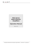
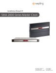
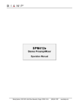
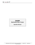
TM MCA Series Multi-Channel Amplifiers Operation Manual Biamp Systems, 10074 S.W. Arctic Drive, Beaverton, Oregon 97005 U.S.A. an affiliate of Rauland Borg Corp. (503) 641-7287 www.biamp.com blank print update June 17,2002 MCA Series INTRODUCTION TABLE OF CONTENTS Introduction pg. 1 Safety Information pg. 2 Front Panel pg. 3 Rear Panel pgs. 4 & 5 MCA Series Multi-Channel Amplifiers provide eight channels of power amplification. Model MCA 8050 delivers 50 watts/channel into 4 ohms. Model MCA 8150 delivers 150 watts/channel into 4 ohms. Channels may be bridged in pairs for higher combined wattage. Connections are provided for remote control of channel levels & muting. MCA Series amplifiers are covered by Biamp Systems' five-year warranty. MCA Series features include: Bridging / Remote Control pg. 6 ♦ 8 channels of 50W (MCA 8050) or 150W (MCA 8150) Applications Specifications Warranty pgs. 7 & 8 pg. 9 ♦ channels may be bridged in pairs for combined power ♦ terminals for remote control of channel levels/muting ♦ balanced line-level inputs on plug-in barrier strips ♦ rear panel level controls & high-pass filter switches ♦ amplifier outputs on screw-terminal connectors ♦ dual-color signal/peak indicators on front & rear panels ♦ front panel indicators for amplifier temp/load faults ♦ fan cooled with complete output/speaker protection ♦ optional transformers for 25/70/100 Volt systems ♦ incorporates AES recommended grounding practices ♦ CE marked & UL / C-UL listed ♦ covered by BiampSystems' five-year warranty 1 IMPORTANT SAFETY INFORMATION Do not install near any heat sources such as radiators, heat registers, stoves, or other apparatus (including amplifiers) that produce heat. Read these instructions. Keep these instructions. Do not defeat the safety purpose of the polarized or grounding-type plug. A polarized plug has two blades with one wider than the other. A grounding type plug has two blades and a third grounding prong. The wide blade or the third prong are provided for your safety. When the provided plug does not fit into your outlet, consult an electrician for replacement of the obsolete outlet. Heed all warnings. Follow all instructions. Do not use this apparatus near water. Clean only with a dry cloth. Do not block any of the ventilation openings. Protect the power cord from being walked on or pinched particularly at plugs, convenience receptacles, and the point where they exit from the apparatus. Install in accordance with the manufacturers instructions. WARNING - To reduce the risk of electric shock, do not expose this apparatus to rain or moisture. Refer all servicing to qualified service personnel. Servicing is required when the apparatus has been damaged in any way, such as power-supply cord or plug is damaged, liquid has been spilled or objects have fallen into the apparatus, the apparatus has been exposed to rain or moisture, does not operate normally, or has been dropped. The apparatus shall not be exposed to dripping or splashing and no objects, such as vases, shall be placed on the apparatus. Unplug this apparatus during lightning storms or when unused for long periods of time. 2 FRONT PANEL MCA 8050 front panel MCA 8050 signal peak temp fault Channel 1 signal peak temp fault Channel 2 signal peak temp fault Channel 3 signal peak temp fault Channel 4 signal peak temp fault Channel 5 signal peak temp fault Channel 6 signal peak temp fault Channel 7 signal peak temp fault on Channel 8 MCA 8150 front panel MCA 8150 signal peak temp fault Channel 1 signal peak temp fault Channel 2 signal peak temp fault Channel 3 signal peak temp fault Channel 4 signal peak temp fault Channel 5 signal peak temp fault Channel 6 signal peak temp fault Channel 7 signal peak temp fault on Channel 8 Temp / Fault Indicators: These red LEDs indicate overtemperature and output fault conditions for each channel. When an LED remains lit, that channel has an over-temperature condition. When an LED is flashing, that channel has an output fault condition. Either condition will temporarily de-activate the channel, causing the Signal / Peak LED to turn off as well. The channel will attempt to self-reset once the over-temperature or output fault condition is resolved. Signal / Peak Indicators: These 2-color LEDs indicate the signal level for each channel. When an LED is green, that channel has signal (above -30dB). When an LED is red, that channel signal is clipping (max. power). CAUTION: Signal levels should be adjusted to avoid clipping. Clipping can cause severe distortion, over-temperature conditions, and even loudspeaker damage. NOTE: Signal / Peak indicators will turn off during Temp / Fault conditions (see Temp / Fault Indicators below). On Indicator: This green LED remains lit when AC power is applied to the unit. 3 REAR PANEL OFF OFF OFF 2 outputs 1 level level 2 outputs 1 level level 2 outputs 1 level level 2 outputs HPF BRIDGE HPF input 3 level signal / peak level OFF OFF OFF input 1 2 OFF OFF OFF outputs level signal / peak 4 input 5 115V 50/60Hz 900 Watts 3 level OFF OFF OFF input MADE IN U.S.A. signal / peak outputs an affiliate of Rauland Borg Corp. 4 HPF BRIDGE HPF 6 input BIAMP SYSTEMS OFF OFF OFF ~ input 7 level signal / peak outputs input level signal / peak 8 level OFF OFF OFF O level 5 6 HPF BRIDGE HPF LISTED COMMERCIAL AUDIO EQUIPMENT E158021 52SJ signal / peak US OFF OFF OFF R RISK OF ELECTRICAL SHOCK. DO NOT OPEN. 7 8 HPF BRIDGE HPF C UL MCA 8050 CAUTION remote control signal / peak CAUTION: Risk of fire replace fuse only with same type F 10 A H 250 V signal / peak FUSE FUSE MCA 8050 115VAC rear panel input Class 2 Wiring input 1 2 input 3 signal / peak outputs level signal / peak 4 input 5 230V 50/60Hz 900 Watts 3 level HPF BRIDGE HPF input MADE IN U.S.A. signal / peak outputs an affiliate of Rauland Borg Corp. 4 HPF BRIDGE HPF 6 input BIAMP SYSTEMS OFF OFF OFF ~ input 7 level signal / peak outputs input level signal / peak 8 level OFF OFF OFF O level 5 6 HPF BRIDGE HPF LISTED COMMERCIAL AUDIO EQUIPMENT E158021 52SJ signal / peak US OFF OFF OFF R RISK OF ELECTRICAL SHOCK. DO NOT OPEN. 7 8 HPF BRIDGE HPF C UL MCA 8050 CAUTION remote control signal / peak CAUTION: Risk of fire replace fuse only with same type T 4 A L 250 V signal / peak FUSE FUSE MCA 8050 230VAC rear panel input Class 2 Wiring MCA 8150 115VAC rear panel remote control outputs level input 1 2 input 3 signal / peak 4 input 5 115V 50/60Hz 1800 Watts level HPF BRIDGE HPF input 3 4 signal / peak outputs MADE IN U.S.A. signal / peak 6 input 7 level an affiliate of Rauland Borg Corp. OFF OFF OFF ~ input level BIAMP SYSTEMS HPF BRIDGE HPF outputs input 5 6 signal / peak 8 level OFF OFF OFF level HPF BRIDGE HPF O 7 8 signal / peak US signal / peak R OFF OFF OFF UL LISTED COMMERCIAL AUDIO EQUIPMENT E158021 52SJ HPF BRIDGE HPF C signal / peak FUSE FUSE CAUTION: Risk of fire replace fuse only with same type F 15 A H 250 V signal / peak MCA 8150 CAUTION RISK OF ELECTRICAL SHOCK. DO NOT OPEN. input Class 2 Wiring MCA 8150 230VAC rear panel remote control Class 2 Wiring 4 outputs level input 3 1 2 input input 1 signal / peak 4 input 5 230V 50/60Hz 1800 Watts level HPF BRIDGE HPF input 3 4 signal / peak outputs input MADE IN U.S.A. signal / peak 6 level an affiliate of Rauland Borg Corp. OFF OFF OFF input 7 level BIAMP SYSTEMS HPF BRIDGE HPF outputs input 5 6 signal / peak 8 level OFF OFF OFF ~ level HPF BRIDGE HPF O 7 8 signal / peak US signal / peak R OFF OFF OFF UL LISTED COMMERCIAL AUDIO EQUIPMENT E158021 52SJ HPF BRIDGE HPF C signal / peak FUSE FUSE CAUTION: Risk of fire replace fuse only with same type T 6.3 A L 250 V signal / peak MCA 8150 CAUTION RISK OF ELECTRICAL SHOCK. DO NOT OPEN. REAR PANEL Output: These screw terminals provide the speaker outputs from the channels. Connect the positive speaker line to the (+) terminal and the negative speaker line to the (-) terminal of the channel being used. The minimum speaker load on an individual channel is 4 ohms. NOTE: When using a pair of channels in 'bridged' mode (see Bridge above), connect the positive speaker line to the (+) terminal of the odd numbered channel and the negative speaker line to the (+) terminal of the even numbered channel. The minimum speaker load for a bridged output is 8 ohms. Output transformers for 25/70/100 Volt speaker systems are available as user-installed options (installation instructions are included with the output transformers). Transformers (by model) are as follows: TDT50 = MCA 8050 individual channels (50 Watts) TDT100 = MCA 8050 bridged channels (100 Watts) TDT150 = MCA 8150 individual channels (150 Watts) TDT300 = MCA 8150 bridged channels (300 Watts) Input: These plug-in barrier strips provide the balanced line-level inputs to the channels. For balanced connection, wire high (+), low (-), and ground ( ). For unbalanced connection, wire high (+) and ground to both ( ) & (-). NOTE: When using a pair of channels in 'bridged' mode (see Bridge below), input signal must be connected to the odd numbered channel. Level: These screw-driver adjustable controls determine the level of input signals allowed into the channels. Level provides a gain range from 'off' (min.) to 'unity' (max.). The Level control is factory set for -24dB of gain, which will produce maximum output power with input signal peaks of +24dBu. For best performance, first adjust the source signals for optimum (maximum) levels, then adjust the MCA Series Level controls for the desired volume. Signal / Peak Indicators: These 2-color LEDs indicate the signal level for each channel. When an LED is green, that channel has signal (above -30dB). When an LED is red, that channel signal is clipping (max. power). CAUTION: Signal levels should be adjusted to avoid clipping. Clipping can cause severe distortion, over-temperature conditions, and even loudspeaker damage. NOTE: Signal / Peak indicators will turn off during Temp / Fault condition (see Temp / Fault Indicators on pg. 3). Remote Control: This 15-pin Sub-D (female) connector provides remote level & muting control of the input channels (see Remote Control on pg. 6). NOTE: When using a pair of channels in 'bridged' mode (see Bridge above), apply Remote Control only to the odd numbered input channel. AC Power Entrance: The switch applies AC power to the unit. The receptacle accepts the detachable AC Power Cord. The AC Power Cord is for connection to three-prong grounded AC outlets. CAUTION: Do not remove or defeat the ground prong on the AC Power Cord, as this constitutes a shock hazard. HPF: These DIP switches provide High-Pass Filters for the input channels. High-Pass Filters are used to eliminate unnecessary lower frequencies (12dB/octave @ 125Hz) for speech and distributed speaker applications. From the factory, the High-Pass Filters are bypassed (switches up). To assign a High-Pass Filter on an input channel, move the switch to the down position. CAUTION: To avoid output fault conditions, High-Pass Filters must be assigned on channels driving 25/70/100 Volt speaker systems (see Output below). Also, any other system equalization affecting frequencies below 125 Hz should remain flat or be used as cut-only. Fuse: MCA 8050 @ 115VAC Fuse = 10A NB. MCA 8050 @ 230VAC Fuse = 4A SB. MCA 8150 @ 115VAC Fuse = 15A NB. MCA 8150 @ 230VAC Fuse = 6.3A SB. Replace Fuse with same type and value only. NOTE: If the Fuse continues to blow (even after checking for proper output connections and speaker loads) the amplifier may require service. Bridge: These DIP switches allow adjacent channels to Bridge together in pairs, for a higher, combined output power (see Bridging on pg. 6). Bridge disables the even numbered input, and applies the odd numbered input signal to both amplifier channels. From the factory, Bridge is bypassed (switches up). To assign Bridge to a pair of channels, move the switch to the down position. 5 BRIDGING / REMOTE CONTROL BRIDGING 1 OFF OFF OFF signal / peak 2 level HPF BRIDGE HPF level input 2 outputs speaker negative input 1 speaker positive REMOTE CONTROL The 15-pin Sub-D (female) Remote Control connector provides terminals for remote level/mute control of Channels 1~8 (see diagram & table on right). A variable control voltage (0~+10 VDC) is used to control levels (+10 VDC = unity gain; 0 VDC = off). Remote Control provides +10V and ground terminals (for use with potentiometers), but external ‘ramp’ voltage devices, such as a BIAMP DRI, may be used instead (see Applications on pg. 8). Potentiometers should be 25kΩ linear taper, and are wired with high to +10V, low to ground, and wiper to the desired channel terminal(s). See examples below. The wiper of a single potentiometer may be wired to multiple control terminals (to control a group of channels). However, wipers from multiple potentiometers should not be connected to a single control terminal (undesirable interaction). Switches, Logic Outputs, or other contact-closures can be used to mute channels, by simply shorting the associated control terminal(s) to ground. A switch may be wired to multiple control terminals (to mute a group of channels). Multiple switches may be wired to a single control terminal, but wiring multiple switches to multiple control terminals would require a diode matrix. The combination of a potentiometer & a switch can be used to perform level adjustment & muting, or to provide an adjustable amount of mute attenuation. NOTE: Remote controls simply decrease volume from a maximum, which is established with the channel Level controls (see Level on previous page). When using a pair of channels in 'bridged' mode (see Bridging above), apply Remote Control only to the odd numbered input channel. remote control 8 7 6 5 4 3 2 1 15 14 13 12 11 10 9 remote control pin number channel 1 pin #1 channel 2 pin #2 channel 3 pin #3 pin #4 channel 4 pin #5 channel 5 pin #6 channel 6 pin #7 channel 7 channel 8 pin #8 +10V pin #9 ground pins #10~15 Channel 1 Mute Channel 1 Level high 8 7 6 5 4 3 2 1 15 14 13 12 11 10 9 8 wiper 7 6 5 4 3 2 1 15 14 13 12 11 10 9 low Channels 1~4 Group Level Channel 1 Level & Mute high 8 7 6 5 4 3 2 1 15 14 13 12 11 10 9 high 8 wiper low 7 6 5 4 3 2 1 15 14 13 12 11 10 9 wiper low 6 signal / peak source signal Bridge DIP switches allow the adjacent odd/even numbered channels to be bridged together in pairs, for a higher, combined output power (see Bridge on previous page). When a pair of channels are bridged, their wattage is combined, but the minimum load increases to 8 ohms (MCA 8050 = 100 watts @ 8 ohms; MCA 8150 = 300 watts @ 8 ohms). Bridge disables the even numbered input, and applies the odd numbered input signal to both amplifier channels. From the factory, Bridge is bypassed (switches up). To assign Bridge to a pair of channels, move the related switch to the down position. Connect the source signal to the odd numbered input channel, connect the positive speaker line to the (+) output terminal of the odd numbered channel, and connect the negative speaker line to the (+) output terminal of the even numbered channel (see diagram on right). NOTE: Only adjacent odd/even numbered channels, which share a common Bridge switch, can be bridged. When channels are bridged, the minimum load is increased to 8 ohms. The negative (-) output terminals on bridged channels are not used (no connection). For remote control of a bridged pair of channels, only the odd numbered input channel requires control (see Remote Control below). APPLICATIONS SURROUND SOUND DVD 1 0:00 Surround Sound sub right rear center left rear left front serial port 27V 50/60 Hz 27 watts class 2 wiring L R L L L L R mute R sig pres L mute R sig pres L override ® SPM 723 sig pres input 6 configured for surround sound support (direct to Aux output) SPM723 ~ right front logic outputs link port link zone output logic inputs main output MSP22e aux output override 7 R line inputs 6 R 5 R 4 3 2 MSP22e 1 mute mic/line 2 mute mic/line 1 MSP22e ADVANTAGE MSP22e Multi-function System Processor ADVANTAGE MSP22e Multi-function System Processor o ADVANTAGE MSP22e Multi-function System Processor o on o on on 115V 50/60Hz 900 Watts input 3 level 2 outputs level input input 1 Class 2 Wiring channels 1 & 2 / 3 & 4 mono-bridged in pairs stereo front speakers L & R stereo rear speakers L & R 7 mono speakers Center & Sub signal / peak outputs 1 2 OFF OFF OFF 4 input 5 level HPF BRIDGE HPF input level signal / peak outputs input 3 4 signal / peak 6 level HPF BRIDGE HPF input 7 level signal / peak outputs input 5 6 signal / peak 8 level BIAMP SYSTEMS an affiliate of Rauland Borg Corp. MADE IN U.S.A. OFF OFF OFF ~ level OFF OFF OFF O 7 8 HPF BRIDGE HPF US RISK OF ELECTRICAL SHOCK. DO NOT OPEN. signal / peak R OFF OFF OFF UL LISTED COMMERCIAL AUDIO EQUIPMENT E158021 52SJ HPF BRIDGE HPF C MCA 8050 CAUTION remote control signal / peak CAUTION: Risk of fire replace fuse only with same type F 10 A H 250 V signal / peak FUSE FUSE MCA 8050 APPLICATIONS PAGE/MUSIC SYSTEM with REMOTE CONTROL background music source optional music assign switches paging microphone 1 COMPACT 2:50 DIGITAL AUDIO zone paging switches DA28R OUTPUTS DA28R ~ 27V 50/60 Hz INPUTS invert logic phantom invert logic phantom BIAMP SYSTEMS Portland, Oregon an affiliate of Rauland-Borg Corp. level level level level level level level level trim trim pad output 8 output 7 output 6 output 5 output 4 output 3 output 2 output 1 CH 1 CH 2 channel 2 set for page-over-music RDP Display Panel IR receiver CH 1 logic inputs CH 2 12 watts class 2 wiring pad +10 +10 preset 1 2 3 4 1 2 3 4 mute mute mute mute 5 6 7 8 mute mute mute mute DRC 4+4 Remote Display Panel WMC Control Panel SELECT 2 3 1 RDC 4 MUTE MUTE MUTE MUTE VOL VOL VOL VOL VOL VOL VOL VOL MUTE MUTE MUTE MUTE VOL VOL VOL VOL VOL VOL VOL mEQ152 VOL 25 5 6 7 40 63 100 160 250 400 630 mEQ152 1K 1.6K 2.5K 4K 6.3K 10K 16K 25 40 63 100 160 250 400 630 1K 1.6K 2.5K 4K boost 8 12dB MASTER 10K 16K ADVANTAGE mEQ152 micro Equalizer gain 25 1 Channel 2 63 100 160 250 400 630 1K 1.6K 2.5K 12dB peak on 2 4K 6.3K 10K 16K 25 40 63 100 160 250 400 630 1K 1.6K 2.5K 4K 6dB out EQ 32 16 8 4 2 1 IR3 IR2 last 2400 9600 19200 gnd 25 40 63 100 160 250 400 630 1.6K 2.5K 4K 6.3K 10K 16K DC out device # serial port baud rate link port remote logic inputs remote display 25 40 63 100 160 250 400 630 1K 1.6K 2.5K boost 12dB 4K 6.3K 10K 16K peak on 6dB out 2 ADVANTAGE mEQ152 micro Equalizer gain EQ in 25 40 63 100 160 250 400 630 1K 1.6K 2.5K 4K 6.3K 10K 16K Channel 2 12dB peak on 1 2 40 63 100 160 250 400 630 1K 1.6K 2.5K 6dB out EQ 6.3K 10K 16K ADVANTAGE mEQ152 micro Equalizer gain 12dB peak on 6dB out -12 Channel 1 in 4K 0 cut EQ in +12 0 peak 6dB out -12 Channel 1 25 boost 12dB 0 cut in MADE IN U.S.A. 12dB 1 +12 0 peak EQ ADVANTAGE mEQ152 micro Equalizer gain 0 -12 Channel 2 mEQ152 1K Portland, Oregon 6dB out control voltage outputs 16K +12 Channel 1 in BIAMP SYSTEMS an affiliate of Rauland-Borg Corp. 10K cut EQ in mEQ152 ~ 27V 50/60 Hz 6.3K 0 peak 6dB out -12 Channel 1 DRI 15 watts class 2 wiring 40 boost 12dB 0 cut EQ in 6.3K +12 0 peak 6dB out 1 Channel 2 2 EQ in 115V 50/60Hz 900 Watts input level 2 outputs input 3 level signal / peak outputs 1 2 OFF OFF OFF 4 input 5 level HPF BRIDGE HPF input level signal / peak outputs input 3 4 signal / peak 6 level OFF OFF OFF ~ input 7 level BIAMP SYSTEMS an affiliate of Rauland Borg Corp. MADE IN U.S.A. HPF BRIDGE HPF outputs input 5 6 signal / peak 8 level signal / peak level OFF OFF OFF O 7 8 HPF BRIDGE HPF US RISK OF ELECTRICAL SHOCK. DO NOT OPEN. signal / peak R OFF OFF OFF UL LISTED COMMERCIAL AUDIO EQUIPMENT E158021 52SJ HPF BRIDGE HPF C MCA 8050 CAUTION remote control signal / peak CAUTION: Risk of fire replace fuse only with same type F 10 A H 250 V signal / peak FUSE FUSE MCA 8050 input 1 Class 2 Wiring optional 25/70/100V transformers (use HPF) zone 8 speakers zone 7 speakers zone 6 speakers zone 5 speakers zone 4 speakers 8 zone 3 speakers zone 2 speakers zone 1 speakers 9 SPECIFICATIONS SPECIFICATION MCA 8050 MCA 8150 individual channel into 4 ohm load 50 watts/channel 150 watts/channel individual channel into 8 ohm load 30 watts/channel 90 watts/channel bridged channels into 8 ohm load 100 watts/channel 300 watts/channel > 85dB > 85dB < 0.2% < 0.2% Intermodulation Distortion (SMPTE): < 0.35% < 0.35% Frequency Response (20Hz~20kHz): +0/-1dB +0/-1dB balanced 20k ohms 20k ohms unbalanced 10k ohms 10k ohms 0.775 Vrms (0dBu) 0.775 Vrms (0dBu) Power Requirements: 115/230 VAC, 50/60Hz 115/230 VAC, 50/60Hz Power Consumption: 900 watts max. 1800 watts max. height 3.5 inches (89mm) - 2U 5.25 inches (133mm) - 3U width 19 inches (483mm) 19 inches (483mm) depth 15.5 inches (394mm) 15.5 inches (394mm) Weight: 30 lbs. (13.6kg) 35 lbs. (15.9kg) Maximum Power Output (@ 2kHz): Signal-to-Noise Ratio (20Hz~20kHz): at rated power into 4 ohms Total Harmonic Distortion + Noise: 20Hz~20kHz @ rated power Input Impedance: Input Sensitivity: Dimensions: Biamp Systems reserves the right to make changes to performance specifications without prior notice. 10 WARRANTY BIAMP SYSTEMS IS PLEASED TO EXTEND THE FOLLOWING 5-YEAR LIMITED WARRANTY TO THE ORIGINAL PURCHASER OF THE PROFESSIONAL SOUND EQUIPMENT DESCRIBED IN THIS MANUAL. BIAMP Systems expressly warrants this product to be free from defects in material and workmanship for a period of 5 YEARS from the date of purchase as a new product from an authorized BIAMP Systems dealer under the following conditions. 1. In the event the warranted BIAMP Systems product requires service during the warranty period, BIAMP Systems will repair or replace, at its option, defective materials, provided you have identified yourself as the original purchaser of the product to any authorized BIAMP Systems Service Center. Transportation and insurance charges to and from an authorized Service Center or the BIAMP Systems factory for warranted products or components thereof to obtain repairs shall be the responsibility of the purchaser. 2. This warranty will be VOIDED if the serial number has been removed or defaced; or if the product has been subjected to accidental damage, abuse, rental usage, alterations, or attempted repair by any person not authorized by BIAMP Systems to make repairs; or if the product has been installed contrary to BIAMP Systems's recommendations. 3. Electro-mechanical fans, electrolytic capacitors, and the normal wear and tear of appearance items such as paint, knobs, handles, and covers are not covered under this warranty. 4. BIAMP SYSTEMS SHALL NOT IN ANY EVENT BE LIABLE FOR SPECIAL, INCIDENTAL, OR CONSEQUENTIAL DAMAGES, INCLUDING LOST PROFITS, LOSS OF USE, PROPERTY DAMAGE, INJURY TO GOODWILL, OR OTHER ECONOMIC LOSS OF ANY SORT. EXCEPT AS EXPRESSLY PROVIDED HEREIN, BIAMP SYSTEMS DISCLAIMS ALL OTHER LIABILITY TO PURCHASER OR ANY OTHER PERSONS ARISING OUT OF USE OR PERFORMANCE OF THE PRODUCT, INCLUDING LIABILITY FOR NEGLIGENCE OR STRICT LIABILITY IN TORT. 5. THIS WARRANTY IS IN LIEU OF ALL OTHER WARRANTIES EXPRESSED OR IMPLIED. BIAMP SYSTEMS EXPRESSLY DISCLAIMS ALL IMPLIED WARRANTIES OF MERCHANTABILITY AND FITNESS FOR A PARTICULAR PURPOSE. THE REMEDIES SET FORTH HEREIN SHALL BE THE PURCHASER'S SOLE AND EXCLUSIVE REMEDIES WITH RESPECT TO ANY DEFECTIVE PRODUCT. THE AGENTS, EMPLOYEES, DISTRIBUTORS, AND DEALERS OF BIAMP SYSTEMS ARE NOT AUTHORIZED TO MODIFY THIS WARRANTY OR TO MAKE ADDITIONAL WARRANTIES BINDING ON BIAMP SYSTEMS. ACCORDINGLY, ADDITIONAL STATEMENTS SUCH AS DEALER ADVERTISEMENTS OR REPRESENTATIONS DO NOT CONSTITUTE WARRANTIES BY BIAMP SYSTEMS. 6. No action for breach of this warranty may be commenced more than one year after the expiration of this warranty. Thank you for purchasing BIAMP SYSTEMS... AMERICAN SOUND CRAFTSMANSHIP Biamp Systems 10074 S.W. Arctic Drive Beaverton, Oregon 97005 (503) 641-7287 http://www.biamp.com 585.0075.00 Declaration of Conformity Biamp Systems, Inc., as the manufacturer, hereby declares that the following described product, in our delivered version, complies with the provisions of the DIRECTIVES except as noted herein. In case of alteration of the product, not agreed upon or directed by us, this declaration is no longer valid. Product Model: ADVANTAGE MCA8050 Product Description: Audio Amplifier Applicable EC Directives: EMC Directive (89/336/EEC), LVD Directive (73/23/EEC) Applicable Harmonized Standards: EN55103-1 emissions EN55103-2 immunity EN60065 safety Special Considerations for Product Environment or Compliance: Shielded cabling must be used for system connections. The apparatus is deemed incapable of producing harmonic emissions or flicker levels sufficient enough to interfere with other apparatus as noted in EN61000-3-2 and EN61000-3-3. RF interference conducted through interconnect cabling or connectors may cause varying degrees of random signal degradation. The effect of increased noise or distortion due to this interference is typically masked by the desired signal. In no instance is operation inhibited. The Technical Report/File is maintained at: Biamp Systems, Inc. 10074 S.W. Arctic Drive Beaverton, OR USA 97005 phone: (503) 641-7287 fax: (503) 626-0281 e-mail: [email protected] Authorized Representative: Steven Hedgepeth Authorized Representative Signature: Issued: February, 2001 Declaration of Conformity Biamp Systems, Inc., as the manufacturer, hereby declares that the following described product, in our delivered version, complies with the provisions of the DIRECTIVES except as noted herein. In case of alteration of the product, not agreed upon or directed by us, this declaration is no longer valid. Product Model: ADVANTAGE MCA8150 Product Description: Audio Amplifier Applicable EC Directives: EMC Directive (89/336/EEC), LVD Directive (73/23/EEC) Applicable Harmonized Standards: EN55103-1 emissions EN55103-2 immunity EN60065 safety Special Considerations for Product Environment or Compliance: Shielded cabling must be used for system connections. The apparatus is deemed incapable of producing harmonic emissions or flicker levels sufficient enough to interfere with other apparatus as noted in EN61000-3-2 and EN61000-3-3. RF interference conducted through interconnect cabling or connectors may cause varying degrees of random signal degradation. The effect of increased noise or distortion due to this interference is typically masked by the desired signal. In no instance is operation inhibited. The Technical Report/File is maintained at: Biamp Systems, Inc. 10074 S.W. Arctic Drive Beaverton, OR USA 97005 phone: (503) 641-7287 fax: (503) 626-0281 e-mail: [email protected] Authorized Representative: Steven Hedgepeth Authorized Representative Signature: Issued: February, 2001