1
Campbell Scientific Proprietary Information. Not to be distributed
out of house without express permission from Campbell Scientific, Inc.
BMP5 Transparent Commands
Revision: 9/08
C o p y r i g h t © 2 0 0 5 - 2 0 0 8
C a m p b e l l S c i e n t i f i c , I n c .
BMP5 Transparent Commands
Table of Contents
PDF viewers note: These page numbers refer to the printed version of this document. Use
the Adobe Acrobat® bookmarks tab for links to specific sections.
1. Introduction...............................................................1-1
1.1 Communication Layers......................................................................... 1-1
1.2 Packet Structure .................................................................................... 1-2
1.2.1 PakBus Packet Framing and Quote Bytes................................... 1-2
1.3 PakBus Packet Headers ........................................................................ 1-3
1.4 Encoding and Decoding Packets .......................................................... 1-4
1.4.1 Quoting the Message Body and Signature Nullifier ................... 1-4
1.4.2 Unquoting the Message Body and Signature Nullifier ............... 1-4
1.4.3 Signature Nullifier ...................................................................... 1-4
1.4.4 Packet Processing Checklist........................................................ 1-4
2. Protocols and Packet Types....................................2-1
2.1 SerPkt Link-State Sub-Protocol............................................................ 2-1
2.2 PakBus Control Packets (PakCtrl)........................................................ 2-2
2.2.1 Delivery Failure Message (MsgType 0x81) ............................... 2-2
2.2.2 Hello Transaction (MsgType 0x09 & 0x89)............................... 2-3
2.2.3 Hello Request Message (MsgType 0x0e) ................................... 2-4
2.2.4 Bye Message (MsgType 0x0d) ................................................... 2-5
2.2.5 Get/Set String Settings Transactions (MsgType 0x07, 0x87,
0x08, 0x88) .................................................................................... 2-5
2.2.6 DevConfig Transactions ............................................................. 2-6
2.2.6.1 DevConfig Get Settings Message (MsgType 0x0f &
0x8f) ........................................................................................ 2-7
2.2.6.2 DevConfig Set Settings Message (MsgType 0x10 &
0x90) ....................................................................................... 2-8
2.2.6.3 DevConfig Get Setting Fragment Transaction Message
(MsgType 0x11 & 0x91)......................................................... 2-9
2.2.6.4 DevConfig Set Setting Fragment Transaction Message
(MsgType 0x12 & 0x92)......................................................... 2-9
2.2.6.5 DevConfig Control Transaction Message (MsgType
0x13 & 0x93) ........................................................................ 2-10
2.3 BMP5 Application Packets................................................................. 2-11
2.3.1 Please Wait Message (MsgType 0xa1) ..................................... 2-12
2.3.2 Clock Transaction (0x17 & 0x97) ............................................ 2-12
2.3.3 File Transfer and Control Transactions .................................... 2-13
2.3.3.1 File Download Transaction (MsgType 0x1c & 0x9c)..... 2-13
2.3.3.2 File Upload Transaction (MsgType 0x1d & 0x9d) ......... 2-14
2.3.3.3 File Directory Format...................................................... 2-15
2.3.3.4 File Control Transaction (MsgType 0x1e & 0x9e) ......... 2-15
2.3.3.5 Get Programming Statistics Transaction (MsgType
0x18 & 0x98) ........................................................................ 2-17
i
BMP5 Transparent Commands Table of Contents
2.3.4 Data Collection and Table Control Transactions ...................... 2-17
2.3.4.1 Table Definitions ............................................................. 2-17
2.3.4.2 Getting Table Definitions and Table Signatures.............. 2-18
2.3.4.3 Collect Data Transaction (MsgType 0x09 & 0x89) ........ 2-19
2.3.4.4 One-Way Data Transaction (MsgType 0x20 & 0x14) .... 2-20
2.3.4.5 Table Control Transaction (MsgType 0x19 & 0x99) ...... 2-22
2.3.5 Get/Set Values Transaction (MsgType 0x1a, 0x9a, 0x1b,
& 0x9b)......................................................................................... 2-23
3. The CR200 Datalogger............................................. 3-1
3.1
3.2
3.3
3.4
3.5
3.6
3.7
Dealing with Unexpected, Asynchronous Commands from the CR2003-1
Getting the Attention of the Datalogger................................................ 3-1
Getting the PakBus Address of the CR200........................................... 3-2
Getting and Setting CR200 Settings ..................................................... 3-2
Getting and Setting the CR200 Clock................................................... 3-3
Datalogger Program Structure .............................................................. 3-3
Creating CR200 Programs and the CR200 Compiler ........................... 3-4
3.7.1 Discovering the CR200 OS Version ........................................... 3-4
3.7.2 Sending a Program to the CR200................................................ 3-5
3.7.3 Interpreting the Response............................................................ 3-7
3.7.4 Handling Rejection...................................................................... 3-7
3.8 Understanding Table Definitions and Table Signatures ....................... 3-8
3.9 Getting Table Definitions from the CR200........................................... 3-8
3.9.1 How to Get and Use Table Signatures ........................................ 3-8
3.10 Retrieving Data from the CR200 ........................................................ 3-9
3.10.1 Interpreting Data Types............................................................. 3-9
3.10.2 Data Collection Sequence ......................................................... 3-9
3.10.3 Collecting Tables and Specific Records.................................. 3-10
3.10.4 Getting Values from Specific Records.................................... 3-11
3.11 Controlling Packet Size..................................................................... 3-11
4. The CR1000 Type Datalogger ................................. 4-1
4.1
4.2
4.3
4.4
4.5
4.6
4.7
Dealing with Unexpected Commands................................................... 4-1
Getting the Attention of the Datalogger and Establishing a Baud Rate 4-1
Getting the PakBus Address ................................................................. 4-2
Getting and Setting Datalogger Settings ............................................... 4-2
Getting and Setting the Clock ............................................................... 4-3
The Program Structure .......................................................................... 4-3
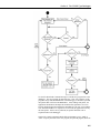
Sending a Program to the Datalogger ................................................... 4-4
4.7.1 Interpreting the Response............................................................ 4-6
4.7.2 Handling Rejection...................................................................... 4-6
4.7.3 Erasing Files on the CFM100...................................................... 4-6
4.7.4 Deleting Program Files................................................................ 4-7
4.8 Understanding Table Definitions and Table Signatures ....................... 4-7
4.9 Getting Table Definitions...................................................................... 4-8
4.9.1 How to Get and Use Table Signatures......................................... 4-8
4.10 Retrieving Data ................................................................................... 4-8
4.10.1 Interpreting Data Types............................................................. 4-9
4.10.2 Data Collection Sequence ......................................................... 4-9
4.10.3 Collecting Tables and Specific Records.................................... 4-9
4.10.4 Getting Values from Specific Records.................................... 4-10
ii
BMP5 Transparent Commands Table of Contents
4.11 Collecting Files from the Datalogger................................................ 4-11
4.12 Controlling Packet Size .................................................................... 4-11
Appendices
A. Data Types Summary ............................................. A-1
B. Calculating Packet Signatures and the
Signature Nullifier................................................. B-1
C. Device Description Files......................................... C-1
D. JAVA Example Code............................................... D-1
Glossary
iii
BMP5 Transparent Commands Table of Contents
iv
Section 1. Introduction
This document outlines the structure for a fundamental subset of protocols and packet
types used to communicate directly with a single PAKBUS® datalogger. The protocols and
packet types discussed in this document are collectively referred to as BMP5 and are used
to communicate with Campbell Scientific’s native PakBus dataloggers (CR200 Series,
CR1000, CR3000, etc.). This documentation assumes the communication link to the
datalogger has already been established. Therefore, packets are created, sent, and
received over a transparent link directly to and from a single datalogger.
While this document only discusses essential packet types that facilitate communication
with a single datalogger, the creation of these packets requires an understanding of packetswitched protocols. With this understanding and through the use of this reference, a
developer should be able to send basic packets to and receive packets from a Campbell
Scientific CR200 or CR1000 type datalogger.
1.1 Communication Layers
Like other types of packet switched communication protocols such as TCP/IP,
transparent BMP5 communication relies on a low-level network protocol and
higher application level protocols. These different protocol layers exist to
facilitate communication between applications and nodes across a given
medium. The benefit of using protocol layers is that each layer becomes
responsible for a specific function that assists communication. Since these
functions are presented in manageable blocks, end-to-end communication is
easier because each layer focuses on a single responsibility.
The way a single layer handles a specific task internally can change as long as
communication to the protocol layer above and the protocol layer below
continues to function in the same manner. For example, the command to check
a datalogger clock may exist in the application layer while a separate layer
handles the connection. As long as these separate layers communicate with
each other, the information can be organized and sent across the network as a
complete packet.
The protocol types discussed in this document are the SerPkt Protocol used to
monitor the state of the communication link, the PakBus Control Protocol
(PakCtrl) used to facilitate PakBus network-level services, and the BMP5
Protocol used to send application messages. An understanding of these
message types and the packet structure for these protocols will be necessary to
send basic packets to and receive basic packets from a native PakBus
datalogger.
1-1
Section 1. Introduction
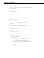
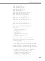
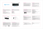
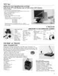
1.2 Packet Structure
1 byte
Header (8 bytes)
Message (0...998 bytes)
2 bytes
1 byte
Signature Nullifier
Message Body
Transaction ID 1 byte
Message type 1 byte
Source node ID 12 bits MSB first
Hop count 4 bits
Destination node ID 12 bits MSB first
Hi proto code 4 bits
Source physical address 12 bits MSB first
Priority 2 bits
Expect more code 2 bits
Destination physical address 12 bits MSB first
Link State 4 bits
The first and last bytes are 0xbd to mark the beginning and end of a packet
1.2.1 PakBus Packet Framing and Quote Bytes
PakBus data packets always end with a reserved or special byte code called a
SerSyncByte (0xbd1) used to identify and isolate each complete packet. Also,
one or more SerSyncBytes are transmitted before a data packet. Sending extra
SerSyncBytes through an RS-232 interface will clear residual characters from
the receiving node’s input buffer or wake the node up in preparation for
communication.
1
The character string (0xbd) designates that the characters “bd” are actually
hexadecimal representations of the values within the transmission. The
character sequence “0x” is a common hexadecimal prefix notation and is used
throughout this document when referring to hexadecimal values. Please note
that when viewing included log files, the characters “bd” will appear without
the “0x” prefix. For reference, the hexadecimal value “b” correlates to the
decimal value “11” or the binary value of “1011” while the hexadecimal value
“d” correlates to the decimal value “13” or the binary value of “1101”.
1-2
Section 1. Introduction
To ensure that a SerSyncByte doesn’t appear inadvertently within the message
data, it must be recognized and quoted within the body of the packet before the
packet is transmitted. The quoting process is accomplished by replacing
reserved bytes with a special code called the QuoteByte. Both SerSyncBytes
and QuoteBytes must be found in the packet body and replaced with the
following sequence:
SerSyncByte (0xbd) becomes (0xbc 0xdd)
Quote Byte (0xbc) becomes (0xbc 0xdc)
Remember that when receiving a packet, the quoted two-byte codes must be
recognized and replaced within the message body by its corresponding value in
order to interpret the data correctly.
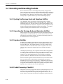
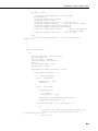
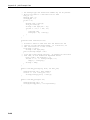
1.3 PakBus Packet Headers
Along with a SerSyncByte, each packet must contain a PakBus header with the
appropriate information to complete the transaction. The header will contain
the following:
PakBus Header Information:
Name
LinkState
Type
bits 7..4
DstPhyAddr
ExpMoreCode
12 bits
bits 7..6
Priority
bits 5..4
SrcPhyAddr
12 bits
HiProtoCode
bits 7..4
DstNodeId
12 bits
HopCnt
SrcNodeId
bits 7..4
12 bits
Description
The state of the link described binaurally:
1000: off-line
1001: ring
1010: ready
1011: finished
1100: pause
Address where this packet is going (MSB first)
Describes whether the client should expect
another packet from this transaction.
0x00: This is the last message to this
destination from this source
0x01: Expect more messages to this destination
from the same source
0x02: Neutral message that has no impact on
whether to expect more
0x03: Expect more messages in the reverse
direction
The message priority on the network. Ranges
from the lowest priority, 00, to the highest
priority, 03. Priority 01 will be sufficient for
normal communication.
Address of the node that sent the packet (MSB
first)
Designates the type of higher level protocol
that will be contained in this packet:
0x00: PakCtrl Message
0x01: BMP5 Message
Node ID of the message destination (MSB
first)
Always zero when connected directly
Node Id of the message source (MSB first)
1-3
Section 1. Introduction
1.4 Encoding and Decoding Packets
Reserved characters must be acknowledged and quoted by the application
before sending a packet and also recognized and decoded before the application
processes a packet. These reserved characters are the SerSyncByte, 0xbd, and
the QuoteByte, 0xbc. When these special characters are found within the
message body or signature nullifier, they must be handled appropriately.
1.4.1 Quoting the Message Body and Signature Nullifier
Use a QuoteByte, 0xbc, to mark places in the message body or signature
nullifier where the SerSyncByte, 0xbd, or the QuoteByte, 0xbc, appear before
transmitting the packet. The value of the byte following the QuoteByte is the
sum of the quoted character and 0x20. All packets sent by the application must
encode the message body and signature nullifier in this manner. An example
of packet encoding can be found in the JAVA code in Appendix D.
1.4.2 Unquoting the Message Body and Signature Nullifier
When a packet is received, the application must parse through the message and
signature nullifier to find and replace any reserved characters that have been
quoted before processing the message. An example of decoding a packet can
be found in the JAVA code in Appendix D.
1.4.3 Signature Nullifier
In addition to the PakBus header and packet framing implementation, packets
are checked for errors through the use of a two-byte signature nullifier at the
end of the data frame. The signature nullifier is a two-byte code that when
calculated with the rest of the data frame results in a signature value of zero.
Of course, the packet must be unquoted prior to the signature calculation
process.
Checking the packet integrity with a signature nullifier enables the application
to calculate a running signature as bytes are received and then simply check to
see if the signature is zero when the trailing SerSyncByte is received. If the
signature is zero, the framed data must be correct and can be confidently
processed. Otherwise, the data has become corrupt and must be discarded.
Please note that the signature nullifier field must always be checked to ensure
that reserved characters are quoted before transmitting the message and
decoded before processing a received message. Additional descriptions of the
signature and signature nullifier algorithms and example C code can be found
in Appendix B. An additional example of the signature and signature nullifier
algorithm can be found in the JAVA code in Appendix D.
1.4.4 Packet Processing Checklist
Data packets received by an application must be examined and processed. The
necessary steps to accomplish this process first require that all reserved
characters be unquoted in the message body and signature nullifier. After all
special characters are unquoted in the packet and signature nullifier but before
1-4
Section 1. Introduction
processing the packet information, the application should make the following
checks:
1.
Check the length of the packet. If the entire packet length is less than 4
bytes or greater than 1010 bytes, it should be considered invalid and
discarded.
2.
The DstPhyAddr and DstNodeId fields within the packet header should
both equal the address of the application or the broadcast address.
3.
The SrcPhyAddr and SrcNodeId in the header should be equal to the
address of the datalogger with which the application is communicating.
4.
The signature of the entire packet, excluding the SerSyncBytes, should be
zero. A non-zero signature indicates a corrupt data packet.
1-5
Section 1. Introduction
This is a blank page.
1-6
Section 2. Protocols and Packet Types
Packet types from three distinct protocols are described in this document. The SerPkt
Protcol used to monitor the state of the communication link, the PakBus Control Protocol
(PakCtrl) used to facilitate PakBus network-level services, and the BMP5 Protocol used to
send application messages.
2.1 SerPkt Link-State Sub Protocol
SerPkt protocol allows the application and the datalogger to track and control
the state of their communication link on the network. The application can
request the datalogger’s state before attempting to send messages with a “ring”
packet. If the datalogger responds with a “ready” packet, the application
should be able to proceed with communication.
Some possible link-states sent by the application and a possible response from
the datalogger, depending on the state of the device, include but are not limited
to the following few examples:
Ring –> Ready
Ready with a message –> Ready with data
Finished with a message –> Ready with data
Finished –> Off-line
Pause –> Finished with or without data
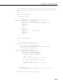
The SerPkt protocol discussed in this section is the Link-state Sub Protocol. If
the developer can communicate between the application and the datalogger
with this protocol layer, all other protocols discussed in this document should
be implemented easily as additional layers working with this SerPkt protocol.
With Link-state Sub Protocol communication, a node initiates a link check and
the receiving node responds with a corresponding Link-state Sub Protocol
packet declaring the current state. Packets with four bytes of data will only
contain the state of the communications link while packets with more than four
bytes of data will contain additional link information and possibly even
message data. The format for this packet is outlined in the following table.
2-1
Section 2. Protocols and Packet Types
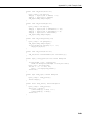
Link-State Sub-protocol Packet Format:
Name
LinkState
Type
bits7..4
DstPhyAddr
ExpMoreCode
12 bits
bits 7..6
Priority
bits 5..4
SrcPhyAddr
{ HiProtoCode
DstPBAddr
HopCnt
SrcPBAddr
{ MsgData }}
12 bits
bits 7..4
12 bits
bits 7..4
12 bits
Byte [ ]
Description
The packet type and the link state:
1000: Off-line
1001: Ring
1010: Ready
1011: Finished
1100: Pause
Address where this packet is going
Expect more communication with this same
destination-source pair soon described
binaurally:
00: Last
01: Expect more
10: Neutral
11: Reverse
Priority – Ranges from 0 as the lowest priority
to 3 as the highest priority
Address of the node sending this packet
Designates the higher level protocol
Address where this packet is going
Hop count – measured from the source node
Address of the node sending this packet
Message data
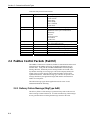
2.2 PakBus Control Packets (PakCtrl)
The PakBus Control Protocol (PakCtrl) facilitates communication and network
management on the PakBus network by exchanging information between
network nodes. Along with the standard PakBus header and SerSyncByte
framing characters, all PakCtrl protocol message bodies also include a twobyte header consisting of a message type code used to uniquely identify the
format of the rest of the message and a transaction number used to detect
orphaned transactions. While the message type code must be specific to the
message that follows, the application assigns and monitors the transaction
number for each packet.
The PakCtrl message types that an application must be aware of and
understand include the following:
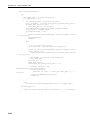
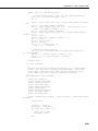
2.2.1 Delivery Failure Message (MsgType 0x81)
The delivery failure or fault message is generated at any node on the network
when a message cannot be delivered. To avoid an endless loop, fault messages
are not generated when an existing fault message cannot be delivered.
2-2
Section 2. Protocols and Packet Types
Delivery Failure Message Format (MsgType 0x81):
Name
MsgType
TranNbr
ErrCode
Type
Byte
Byte
Byte
HiProtoCode
bits 7..4
DstPBAddr
12 bits
HopCnt
SrcPBAddr
MsgData
bits 7..4
12 bits
Byte [0..16]
Description
Message type code (0x81)
Transaction number (always zero)
Failure code:
0x01: Unreachable
0x02: Unreachable higher level protocol
0x03: Queue overflow (timed out or out of
resources)
0x04: Unimplemented command or MsgType
0x05: Malformed message
0x06: Link failed
High level protocol code from the original
message
Destination node address from the original
message
Hop count from the original message
Source node address from the original message
Up to 16 bytes of MsgData from the original
message
2.2.2 Hello Transaction (MsgType 0x09 & 0x89)
The Hello transaction is used to verify that two-way communication can occur
with a specific node. An application does not have to send a Hello command to
the datalogger but the datalogger may send a Hello command to which the
application should respond.
It is important that the application copy the exact transaction number from the
received Hello command meassage into the Hello response sent to the
datalogger. Since the application is connected directly to the datalogger, the
hop metric received in the command message packet from the datalogger can
be copied by the application and inserted in the response message packet. In
addition, the application should not identify itself as a router in the IsRouter
parameter of the response message packet.
Hello Command Message Format (MsgType 0x09):
Name
MsgType
TranNbr
IsRouter
Type
Byte
Byte
Byte
Description
Message type code (0x09)
Transaction number
Indicates whether the source node is a router:
0x00: False
0x01: True
2-3
Section 2. Protocols and Packet Types
Name
HopMetric
Type
Byte
VerifyIntv
Uint2
Description
A code used to indicate the worst case interval
for the speed of the link required to complete a
transaction (default value of 0x02):
0x00: 200 msec or less
0x01: 1 sec or less
0x02: 5 sec or less (default for RS232 or
TCP/IP)
0x03: 10 sec or less
0x04: 20 sec or less
0x05: 1 min or less
0x06: 5 min or less
0x07: 30 min or less
Link verification interval in seconds
Hello Response Message Format (MsgType 0x89):
Name
MsgType
TranNbr
IsRouter
Type
Byte
Byte
Byte
HopMetric
Byte
VerifyIntv
Uint2
Description
Message type code (0x89)
Transaction number
Indicates whether the source node is a router.
The application should specify 0x00 (False)
indicating it is not a router in the response
message.
0x00: False
0x01: True
A code used to indicate the worst case interval
for the speed of the link required to complete a
transaction (default value of 0x02). The
application should copy the value from the
command message :
0x00: 200 msec or less
0x01: 1 sec or less
0x02: 5 sec or less (default for RS232 or
TCP/IP)
0x03: 10 sec or less
0x04: 20 sec or less
0x05: 1 min or less
0x06: 5 min or less
0x07: 30 min or less
This value is the link verification interval from
the Hello Command message divided by 2.5.
2.2.3 Hello Request Message (MsgType 0x0e)
A one-way message used to trigger a Hello transaction from the recipient. Use
this message to initiate communication with a node when the address of the
node is not known. If the application receives a Hello Request message from a
datalogger, the best course of action is to return a Hello Message to the
datalogger.
2-4
Section 2. Protocols and Packet Types
Hello Request Message Format (MsgType 0x0e):
Name
MsgType
TranNbr
Type
Byte
Byte
Description
Message type code (0x0e)
Transaction number (always zero)
2.2.4 Bye Message (MsgType 0x0d)
The Bye Message is a one-way message that lets a node on the network know
that the link is shutting down and that the nodes will no longer be able to talk
to each other. Before shutting down a link, like a phone modem connection, it
is good practice to always send a Bye Message.
Bye Message Format (MsgType 0x0d):
Name
MsgType
TranNbr
Type
Byte
Byte
Description
Message type code (0x0d)
Transaction number (always zero)
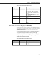
2.2.5 Get/Set String Settings Transactions (MsgType 0x07,
0x87, 0x08, 0x88)
Both the Get Settings and Set Settings transactions are used exclusively when
reading or writing settings in a CR200 series datalogger but only has limited
usage for settings within a CR1000 type datalogger. These datalogger settings
exist as a list of ASCII text variables within the datalogger and are used by the
datalogger like environment variables are used by a personal computer.
Get Settings Command Message (MsgType 0x07):
Name
MsgType
TranNbr
NameList
Type
Byte
Byte
ASCIIZ
Description
Message type code (0x07)
Transaction number
List of names for which you want values. The
names will be separated with an ASCII semicolon character. If this is an empty string, the
datalogger will respond with all settings.
Get Settings Response Message (MsgType 0x87):
Name
MsgType
TranNbr
Settings
Type
Byte
Byte
ASCIIZ
Description
Message type code (0x87)
Transaction number
A string containing a list of name-value pairs
with each name separated by the value with the
“=” sign. Each value-pair is separated with a
semi-colon. For example:
Model=CR200;PakBusAddress=1;
2-5
Section 2. Protocols and Packet Types
Set Settings Command Message (MsgType 0x08):
Name
MsgType
TranNbr
Settings
Type
Byte
Byte
ASCIIZ
Description
Message type code (0x08)
Transaction number
A string containing a list of name-value pairs
with each name separated by the value with the
“=” sign. Each value-pair is separated with a
semi-colon. For example:
Model=CR200;PakBusAddress=1;
Set Settings Response Message (MsgType 0x88):
Name
MsgType
TranNbr
RespCode
Type
Byte
Byte
Byte
{ FailOffset }
UInt2
Description
Message type code (0x88)
Transaction number
Response code:
0x00: Complete
0x01: Read-only
0x02: Out of space
0x03: Syntax error
0x04: Access denied
Offset from the start of the settings string to the
name of the variable that caused the command
to be rejected.
If a list of variables is specified while using the Set Settings transaction, the
datalogger will process the settings one at a time until it finishes or until a
setting fails to process. When a failure occurs, the response message will
report the offset into the settings string where the offending setting starts. All
settings up to the offending one are acceptable but the settings after the
offending setting have not been evaluated by the datalogger.
Some examples of possible settings include:
•
•
•
•
Model: The datalogger model name or number
Version: The version of the datalogger
SerialNbr: The serial number of the datalogger
PakBusAddress: The PakBus address of the datalogger
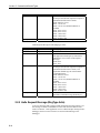
2.2.6 DevConfig Transactions
Applications should use the DevConfig transactions to get settings from and set
settings in a CR1000 type datalogger. The DevConfig transactions are a subset
of the PakCtrl protocol.
Settings are variables within the operating system of a datalogger that control
operation and can be changed by the user. An application using DevConfig
transactions can obtain the values for these settings and change these settings if
necessary.
2-6
Section 2. Protocols and Packet Types
As datalogger operating systems are revised, these settings may change or be
removed. However, the datalogger will always report the major version
number within the setting response message so that an application can be aware
of the current operating system in the datalogger. By knowing the data type
and version number, an application can verify the most current settings for a
datalogger with the CR1000 Device Description File located in the Appendix
of this document. Specific setting IDs can be gleaned from the Device
Description file and used during the creation of an application that
communicates with a CR1000 type datalogger.
2.2.6.1 DevConfig Get Settings Message (MsgType 0x0f & 0x8f)
The Get Settings transaction allows an application to receive all or part of the
datalogger settings. The application sends a command and waits for the
response from the datalogger. If the datalogger has more settings to send than
can fit in a single response message, the MoreSettings parameter is set in the
response. The application must issue another Get Settings message and specify
the BeginSettingId to get the remaining datalogger settings.
DevConfig Get Settings Command (MsgType 0x0f):
Name
MsgType
TranNbr
SecurityCode
{ BeginSettingId
Type
Byte
Byte
UInt2
UInt2
{ EndSettingId }}
UInt2
Description
Message type code (0x0f)
Transaction number
The security code of the datalogger
Allows the application to specify the first
setting for the datalogger to include in the
response message.
Allows the application to specify the last
setting the datalogger should include in the
response message.
DevConfig Get Settings Response (MsgType 0x8f):
Name
MsgType
TranNbr
Outcome
Type
Byte
Byte
Byte
{ DeviceType
UInt2
MajorVersion
Byte
MinorVersion
Byte
Description
Message type code (0x8f)
Transaction number
Specifies the outcome of the transaction:
0x01: The transaction succeeded and values
will follow
0x02: The security code is invalid
Specifies a code that identifies the type of
device that is sending the response:
0x0c: CR1000 type datalogger
Identifies the version number for the device.
The application can use a combination of the
DeviceType and MajorVerion to identify the
settings that should be supported by the device
through the Device Description XML file.
Identifies the version number to determine how
settings for a device are to be interpreted. For
example, a device might support a different
baud rate in one version than in another
version.
2-7
Section 2. Protocols and Packet Types
Name
MoreSettings
Type
Boolean
{ SettingId
LargeValue
UInt2
bit 15
ReadOnly
SettingLen
bit 14
bit 13..0
SettingValue }}
Byte [1..988]
Description
Set to true by the datalogger when it has more
settings to send than are in this response
message
Identifies the specific setting being described
Set to 1 if the setting value is larger than will
fit into the 988 byte packet size limit for a
DevConfig protocol packet
Set to 1 if this setting is read only
Specifies the length in bytes of the setting that
will follow. If LargeValue is set to true, the
value that follows will be the first fragment of
the message and subsequent fragments must be
retrieved using the DevConfig Get Setting
Fragment transaction.
The value of the setting. The Binary format of
this field depends on the setting type declared
in the Setting Id parameter.
2.2.6.2 DevConfig Set Settings Message (MsgType 0x10 & 0x90)
The Set Settings transaction allows an application to change the value of one or
more settings in the datalogger. The application sends the command message
and waits for the datalogger’s response message. The datalogger will not
activate the new setting until the client sends a Control message to commit the
setting. The datalogger will timeout after forty seconds and resume normal
operations based on previous settings if it has not received an additional Set
Settings command or a commit message.
DevConfig Set Settings Command (MsgType 0x10):
Name
MsgType
TranNbr
SecurityCode
{ SettingId
SettingLen
SettingValue }
Type
Byte
Byte
UInt2
UInt2
UInt2
Byte [ ]
Description
Message type code (0x10)
Transaction number
The security code of the datalogger
The identity of the setting that follows
The length in bytes of the SettingValue
The value for the setting
DevConfig Set Settings Response (MsgType 0x90):
2-8
Name
MsgType
TranNbr
Outcome
Type
Byte
Byte
Byte
{ SettingId
UInt2
Description
Message type code (0x90)
Transaction number
The outcome of the transaction:
0x01: The transaction succeeded
0x02: The security code is invalid or does not
provide sufficient access to set settings
0x03: Another client has already made changes
that have not been committed
The setting identifier from the Set Settings
command
Section 2. Protocols and Packet Types
Name
SettingsOutcome }
Type
Byte
Description
Specifies the outcome of the set attempt:
0x01: Setting value tagged to be changed
0x02: Setting identifier was not recognized
0x03: Setting value malformed or out of range
0x04: Setting is read-only
0x05: Not enough memory to store the setting
2.2.6.3 DevConfig Get Setting Fragment Transaction Message (MsgType
0x11 & 0x91)
The Get Setting Fragment transaction allows an application to ask for part of a
setting value. This transaction is used if the setting value is too large for a
single packet. Typically, an application will use the Get Settings transaction to
retrieve a setting. However, if the LargeValue flag is set, the application can
get the rest of the setting value using this transaction.
DevConfig Get Setting Fragment Command (MsgType 0x11):
Name
MsgType
TranNbr
SecurityCode
SettingId
Type
Byte
Byte
UInt2
UInt2
Offset
Uint4
Description
Message type code (0x11)
Transaction number
The security code of the datalogger
The identifier of the setting value that should
be returned
The offset from the start of the setting value
where the requested fragment should start
DevConfig Get Setting Fragment Response (MsgType 0x91):
Name
MsgType
TranNbr
Outcome
Type
Byte
Byte
Byte
{ MoreFragments
bit 15
FragmentSize
FragmentData }
bits 14..0
Byte [ ]
Description
Message type code (0x91)
Transaction number
The outcome of the transaction:
0x01: The transaction succeeded and the values
will follow
0x02: The security code is invalid or does not
provide sufficient access to read the setting
0x03: The transaction is not supported by this
device
If set to true, there are more fragments that can
be sent for this setting
The size of this fragment in bytes
The fragment of the setting
2.2.6.4 DevConfig Set Setting Fragment Transaction Message (MsgType
0x12 & 0x92)
The Set Setting Fragment Transaction is used to send settings to the datalogger
that are too large to fit in a single packet.
2-9
Section 2. Protocols and Packet Types
DevConfig Set Setting Fragment Command (MsgType 0x12):
Name
MsgType
TranNbr
SecurityCode
SettingId
Type
Byte
Byte
UInt2
UInt2
FragmentOffset
MoreFragments
UInt4
bit 15
FragmentLen
bits 14..0
FragmentData
Byte [ ]
Description
Message type code (0x12)
Transaction number
The security code of the datalogger
The identifier of the setting value that should
be returned
The starting offset for this fragment
If set to true, the application has more
fragments to send for this setting
The length in bytes of the setting value to
follow
The setting fragment data
DevConfig Set Setting Fragment Response (MsgType 0x92):
Name
MsgType
TranNbr
Outcome
Type
Byte
Byte
Byte
Description
Message type code (0x92)
Transaction number
The outcome of the transaction:
0x01: The setting value was tagged for change
or the fragment was accepted
0x02: The security code is invalid or does not
provide sufficient access to set settings
0x03: The setting identifier was not recognized
0x04: The setting value was malformed or out
of range
0x05: The setting is considered read-only
0x06: Not enough memory to store the setting
0x07: This device does not support this
transaction
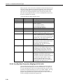
2.2.6.5 DevConfig Control Transaction Message (MsgType 0x13 & 0x93)
The Devconfig Control transaction controls what the datalogger does with the
settings it has in memory. The application uses this transaction to tell the
datalogger to commit changes to permanent storage, cancel any changes, revert
all settings to the device defaults, or refresh the session timer.
The datalogger has a forty-second session timer that gets set or reset each time
a valid message is received from the client. When this timer expires, the
datalogger will rollback any changes that have not been committed.
DevConfig Control Command (MsgType 0x13):
Name
MsgType
TranNbr
SecurityCode
2-10
Type
Byte
Byte
UInt2
Description
Message type code (0x13)
Transaction number
The security code of the datalogger
Section 2. Protocols and Packet Types
Name
Action
Type
Byte
Description
The action that should be taken by the
datalogger
0x01: Commit the changes and exit
0x02: Cancel any changes and exit back to a
mode where a new session can be started
0x03: Revert all settings to factory defaults.
Note that these settings will not take effect
until they are committed with another instance
of this transaction
0x04: Don’t do anything with the setting at
present but refresh the session timer
0x05: Cancel any changes and reboot the
datalogger
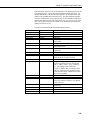
DevConfig Control Response (MsgType 0x93):
Name
MsgType
TranNbr
Outcome
Type
Byte
Byte
Byte
Description
Message type code (0x93)
Transaction number
The outcome of the transaction:
0x01: The settings will be committed and the
device rebooted
0x02: The security code is invalid or does not
provide sufficient access to set settings
0x 03: There are no changes to commit and the
session is ending
0x04: The changed settings will be discarded
and the device will be rebooted
0x05: The settings have reverted to device
defaults but must be committed to take effect
0x06: The session timer has been reset
0x07: The specified action cannot be carried
out because another client has already made
changes to the settings for this device
2.3 BMP5 Application Packets
BMP5 application packets are framed with a PakBus SerSyncByte, 0xbd, and
use the standard eight-byte PakBus header that was used in the PakCtrl
messages. The only difference in the header is the value of the HiProtoCode
parameter. PakCtrl messages have a HiProtoCode parameter of zero while the
header for a BMP5 message has a HiProtoCode parameter of one.
The following are the BMP5 packet types that are necessary for
communication. Keep in mind the general structure of a complete PakBus
packet since the following BMP5 packet type descriptions will only contain
information regarding the message type, transaction number and body of the
packet.
2-11
Section 2. Protocols and Packet Types
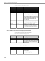
2.3.1 Please Wait Message (MsgType 0xa1)
If the datalogger anticipates it will take more than the default one second to
produce a response after receiving a command, a Please Wait message will be
sent to the client indicating the amount of time the client should wait for a
response to that command. The transaction number of the Please Wait
message will be the same as the command packet on which it is waiting.
After the Please Wait message has been sent, the datalogger will send the
normal transaction response as soon as it is ready. If the datalogger determines
that the response will still take longer than the wait time it just sent, the
datalogger will send another Please Wait message to the application before the
current wait time expires.
Please Wait Message Body (MsgType 0xa1):
Name
MsgType
TranNbr
CmdMsgType
Type
Byte
Byte
Byte
WaitSec
UInt2
Description
Message type code (0xa1)
Transaction number
MsgType of the command on which we are
waiting
Number of seconds to wait for a response (30
second limit).
2.3.2 Clock Transaction (0x17 & 0x97)
The clock transaction can be used to check the current time or to adjust the
datalogger clock. Note the inherent danger of retrying a clock set command. If
the client were to simply retry a failed clock set attempt without knowing
whether the first try reached the station, there is a danger the clock will be
changed more than wanted. If a clock set attempt fails, the client should read
the clock again to determine whether additional adjustments are needed.
Clock Command Body (MsgType 0x17):
Name
MsgType
TranNbr
SecurityCode
Adjustment
2-12
Type
Byte
Byte
UInt2
Nsec
Description
Message type code (0x17)
Transaction number
Security code for the datalogger
Quantity of time to add to the clock. If the
datalogger clock is ahead of the current time,
the Adjustment field should be negative.
Section 2. Protocols and Packet Types
Clock Response Body (MsgType 0x97):
Name
MsgType
TranNbr
RespCode
Type
Byte
Byte
Byte
{ OldTime }
Nsec
Description
Message type code (0x97)
Transaction number
Response code:
0x00: Complete
0x01: Permission denied
Difference between the datalogger clock and
January 1, 1990. This field is not returned
unless RespCode is zero.
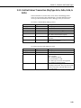
2.3.3 File Transfer and Control Transactions
File transfer and control transactions are used to list datalogger directories,
download datalogger programs, upload datalogger programs, obtain table
definitions, and administer data files. These functions are accomplished by
downloading files to or uploading files from the datalogger and by executing
file control operations on those files. The specific message types are:
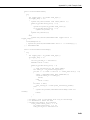
2.3.3.1 File Download Transaction (MsgType 0x1c & 0x9c)
This transaction moves a file from the client application to the datalogger. If
the file is larger than the allowed message size, the client application should
separate the file into fragments, which is called a multiple exchange
transaction. The transaction number must be the same for all file message
fragments since the datalogger uses this number to keep track of entire file
during the transaction. The CloseFlag field listed in the description below is
used to mark the end of the multiple exchange transaction.
The CR200 datalogger has limited memory resources and can not receive a
standard 1000 byte PakBus message. The CR200 dataloggers advertise the
maximum packet size in a device setting called “MaxPktSize” that can be
obtained with the PakCtrl Get Settings transaction. This setting must be used
to adjust the size of the File Download Command message. If a device does
not specify the MaxPktSize setting, the standard 1000-byte PakBus message
size is the limit.
File Download Command Body (MsgType 0xlc):
Name
MsgType
TranNbr
SecurityCode
FileName
Type
Byte
Byte
UInt2
ASCIIZ [0..64]
Attribute
Byte
CloseFlag
Byte
Description
Message type code (0x1c)
Transaction number
Security code of the datalogger
The file name and the device where the file
will be stored. This field may be null after the
first exchange of a multiple fragment
transaction.
A reserved byte that the application must
currently designate as 0x00.
0x00: Keep the file open for more exchanges
0x01: This is the final or only exchange of this
transaction.
2-13
Section 2. Protocols and Packet Types
Name
FileOffset
Type
UInt4
{ FileData }
Byte [ ]
Description
Describes the byte offset into the file of this
fragment. This field will be zero if this is a
single exchange transaction.
The data being sent in this packet
File Download Response Body (MsgType 0x9c):
Name
MsgType
TranNbr
RespCode
Type
Byte
Byte
Byte
FileOffset
UInt4
Description
Message type code (0x9c)
Transaction number
Response Code:
0x00: Complete
0x01: Permission denied
0x02: Insufficient resources or memory full
0x09: Invalid fragment number
0x0d: Invalid file name
0x0e: File is not currently accessible
The FileOffset number from the command
packet to which this is responding
2.3.3.2 File Upload Transaction (MsgType 0x1d & 0x9d)
This transaction moves a file from the datalogger to the client application. The
CloseFlag field, listed in the description below, closes the file and indicates the
End of File. If an attempt to read past the End of File occurs, the datalogger
provides a final response indicating FileData empty and automatically closes
the file without requiring any additional exchanges.
File Upload Command Body (MsgType 0x1d):
Name
MsgType
TranNbr
SecurityCode
FileName
CloseFlag
Type
Byte
Byte
UInt2
ASCIIZ [0..64]
Byte
FileOffset
Swath
UInt4
UInt2
Description
Message type code (0x1d)
Transaction number
Security code for the datalogger
The name of the file to be retrieved
0x00: Keep the file open for more exchanges
on this transaction
0x01: This transaction is the final exchange of
the transaction
Byte offset into the file of the fragment
The number of bytes to read
File Upload Response Body (MsgType 0x9d):
Name
MsgType
TranNbr
2-14
Type
Byte
Byte
Description
Message type code (0x9d)
Transaction number
Section 2. Protocols and Packet Types
Name
RespCode
Type
Byte
FileOffset
{ FileData }
UInt4
Byte [ ]
Description
Response Code:
0x00 – Complete
0x01 – Permission denied
0x0d – Invalid file name
0x0e – File is not currently accessible
Byte offset into the file of this fragment
The file data beginning at FileOffset. If an
attempt was made to read past the end of the
file, then this field will be empty or smaller
than size requested in the Swath parameter of
the command message.
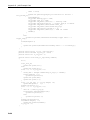
2.3.3.3 File Directory Format
Old programs and other files can be stored in the memory of the CR1000 type
datalogger. To obtain a list of the files maintained in a CR1000 type
datalogger, use the File Upload transaction and specify a file named “.DIR”. A
directory listing of the files being stored on the datalogger will be returned.
The file received in the response message has the following format:
Directory File Format:
Name
DirVersion
{ FileName
FileSize
LastUpdate
{ Attribute }
Type
Byte
ASCIIZ [1..64]
UInt4
ASCIIZ
Byte [0..12]
0x00 }
Byte
Description
File format version
File name
File size in bytes
Date of the last file update
File attribute code. This field may repeat up to
12 times to specify a list of file attributes.
0x01: Running now
0x02: Run on power-up
0x03: Read only
0x04: Hidden
0x05: Program execution paused
File attribute list terminator
2.3.3.4 File Control Transaction (MsgType 0x1e & 0x9e)
The File Control transaction controls compilation and execution of the
datalogger program and manages the files on the datalogger
File Control Command Body (MsgType 0x1e):
Name
MsgType
TranNbr
SecurityCode
FileName
Type
Byte
Byte
UInt2
ASCIIZ [1..64]
Description
Message type code (0x1e)
Transaction number
Security code of the datalogger
File name and device where the file exists. For
example, “CPU:CR1000Program.CR1”.
2-15
Section 2. Protocols and Packet Types
Name
FileCmd
Type
Byte
Description
Code that specifies the command to perform
with the file:
0x01: Compile and run the program and also
make it the “run on power-up” file
0x02: Set the “run on power-up” attribute.
When used with an empty file name argument,
the “run on power-up” attribute will be cleared.
0x03: Make this file hidden
0x04: Delete this file
0x05: Format the device
0x06: Compile and run the file without
deleting the data tables
0x07: Stop the running program
0x08: Stop the running program and delete the
associated files
0x09: Make this file the new datalogger OS
0x0a: Compile and run the program without
changing the “run on power-up” attribute
0x0b: Pause running program execution
0x0c: Resume running program execution
0x0d: Stop the currently running program,
delete associated data files, run the specified
file, and set it to “run on power-up”.
0x0e: Stop the currently running program,
delete associated files, run the specified file,
but don’t change the “run on power-up” setting
File Control Response Body (MsgType 0x9e):
Name
MsgType
TranNbr
RespCode
Type
Byte
Byte
Byte
HoldOff
UInt2
Description
Message type code (0x9e)
Transaction number
0x00 – Complete
0x01 – Permission denied
0x0d – Invalid file name
0x13 – Unsupported FileCmd code
Number of seconds the client should wait
before attempting the next transaction.
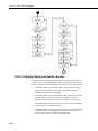
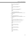
The steps of a complete File Control transaction are shown in this explanation
of a CR200 series datalogger program download:
2-16
1.
Use a File Control command to stop the running program and delete
associated files to make room for the new program
2.
Use File Download to send the new program to the datalogger
3.
Use a File Control command to compile and run the new program
4.
Use Get Programming Statistics to obtain the compile results
Section 2. Protocols and Packet Types
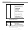
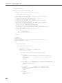
2.3.3.5 Get Programming Statistics Transaction (MsgType 0x18 & 0x98)
The Get Programming Statistics transaction retrieves available status
information from the datalogger.
Get Programming Statistics Command Body (MsgType 0x18):
Name
MsgType
TranNbr
Security Code
Type
Byte
Byte
UInt2
Description
Message type code (0x18)
Transaction number
Security code of the datalogger
Get Programming Statistics Response Body (MsgType 0x98):
Name
MsgType
TranNbr
RespCode
Type
Byte
Byte
Byte
{ OSVer
OSSig
SerialNbr
PowUpProg
CompState
ASCIIZ
UInt2
ASCIIZ
ASCIIZ
Byte
ProgName
ProgSig
CompTime
ASCIIZ [1..64]
UInt2
NSec
CompResult }
ASCIIZ [0..250]
Description
Message type code (0x98)
Transaction number
Response Code:
0x00: Complete
0x01: Permission denied
Datalogger operating system version
Datalogger operating system signature
Datalogger serial number
Name of the “run on power-up” program
Compile and execution status:
0x00: No datalogger program
0x01: Datalogger program running
0x02: Program cannot compile
0x03: Program is paused
Datalogger program name
Datalogger program signature
Time when program was compiled relative to
January 1, 1990.
Compilation result text that exist as one or
more carriage return and line feed separated
lines of ASCII characters with null termination
after the last line
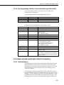
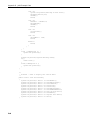
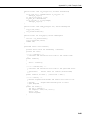
2.3.4 Data Collection and Table Control Transactions
2.3.4.1 Table Definitions
Since dataloggers store data in tables, the datalogger and the application must
understand and agree on the structure of each table in order to collect data.
Table definitions contain the parameters that describe each table, record, and
field in the datalogger and are contained in a file on the datalogger with a
“.TDF” file extension.
Table definitions are used by the application to know what tables and fields
exist and what data to expect from each table when collecting values from the
datalogger. The table definitions specifically describe the data tables, records,
and fields that have been established by the program in the datalogger. These
table definitions are necessary to calculate the table signature for the Collect
2-17
Section 2. Protocols and Packet Types
Data transaction and to describe what data should be returned when collecting
data from a datalogger.
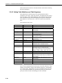
2.3.4.2 Getting Table Definitions and Table Signatures
Table definitions are obtained using a File Upload transaction and are
contained in a file with a “.TDF” file extension. The application only needs to
specify the name “.TDF” and the datalogger will recognize this file extension
in the command message and return the appropriate response containing the
table definitions. The format of the “.TDF” file is shown in the following
table:
Table Definitions File Format:
Name
FslVersion
{ TableName
Table Size
Type
Byte
ASCIIZ
UInt4
TimeType
TblTimeInto
Byte
NSec
TblInterval
NSec
{ ReadOnly
bit 7
FieldType
FieldName
{ AliasName }
bits 6..0
ASCIIZ
ASCIIZ
(0)
Processing
Byte
ASCIIZ
Units
Description
BegIdx
ASCIIZ
ASCIIZ [0..80]
UInt4
Dimension
UInt4
{ SubDim }
(0) }
(0) }
UInt4
UInt4
Byte
Description
File format version. (Use 0x01)
Table Name
Number of records allocated in the datalogger
for this table
Data type code of the “Time Tag” field
“Time Into” part of the “Time Into Interval”
for the table interval
“Interval” part of the table interval (zero means
an event driven table)
0: Read/Write
1: Read-only
Data type of the field
Name of the field in the table
Alias or “FieldName” assigned to the elements
within this field. Currently not used.
Alias names list terminator
Generated by the datalogger, this string
designates the type of processing and
processing parameters used to generate this
field (i.e. “Max”, “Min”, “Avg”, “Tot”, etc.).
Field units
Description of the field
Beginning index. The array index number for
the first element of the array (1 by default or if
not an array).
Array dimension of the whole array (set to 1 if
not an array)
Sub-dimension of a multidimensional array
Sub-dimension list terminator
Field list terminator
There are three implied parameters that are part of the table definitions: Table
Numbers, Field Numbers, and the Table Definition Signature. Table Number
one is the first table. Field Number one is the first field that follows the Time
Tag. Table and Field Numbers are important because they are often used to
specify the location of data in the datalogger in other commands.
2-18
Section 2. Protocols and Packet Types
In order to ensure the integrity of this table information, the application should
calculate a signature of the parameters contained in each table within the table
definitions. One signature should be calculated for each defined table and
should be stored and used by the application to verify that the table has not
changed when collecting data.
The signature is calculated using the parameters for each table from the Get
Table Definitions response. For each table, calculations start with the first byte
of the Table Name and end after the Field List Terminator of that table. A
description of the algorithm used to calculate the signature along with example
code is found in Appendix B. The Table Definition Signature is used to verify
that table definitions have not changed on the datalogger while data collection
operations continue.
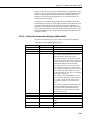
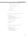
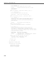
2.3.4.3 Collect Data Transaction (MsgType 0x09 & 0x89)
The Collect Data Transaction is used to collect records from the datalogger.
Collect Data Command Body (MsgType 0x09):
Name
MsgType
TranNbr
Security Code
CollectMode
Type
Byte
Byte
UInt2
Byte
{ TableNbr
TableDefSig
{ P1 }
{ P2 }
UInt2
UInt2
UInt4 or NSec
UInt4 or NSec
{ FieldNbr }
UInt2
(0) }
UInt2
Description
Message type code (0x09)
Transaction number
Security code of the datalogger
Collection mode code:
0x03: Collect from the oldest record in each
table and collect to the newest record.
0x04: Collect from “P1” to the newest record.
If the start record “P1” does not exist and is not
the next record that will be stored, collect will
start from the oldest record in each table.
0x05: Collect the most recent records where
“P1” designates how many records to collect.
0x06: Collect records that lie between “P1” and
“P2”. Include “P1” but exclude “P2”. If no
records exist between “P1” and “P2”, an empty
data response will be sent.
0x07: Collect a Time Swath where “P1” and
“P2” are the time parameters (NSec relative to
Jan 1, 1990). Get all records with time tags
greater than or equal to “P1” and less than
“P2”.
0x08: Collect a partial record when the record
size has exceeded the maximum packet size.
“P1” specifies the record number and “P2”
specifies the byte offset into the record that
was partially retrieved.
Table number
Table definition signature
Parameter used to specify what to collect
Optional parameter used to specify what to
collect
Field number or an empty list to specify all
fields
Field list terminator
2-19
Section 2. Protocols and Packet Types
When a response comes in from this command, the fields after RespCode exist
only if the response indicates the transaction completed. If the response to the
Collect Data Command sets the parameter IsOffset equal to one, the client
must retrieve the remaining fragments of the record by using collect mode
0x08. The client should know the size of the record and therefore know when
the entire record has been collected.
Collect Data Response Body (MsgType 0x89):
Name
MsgType
TranNbr
RespCode
Type
Byte
Byte
Byte
{ { TableNbr
BegRecNbr
IsOffset
UInt2
UInt4
bit 7
NbrOfRecs
15 or 31 bits
{ TimeOfRec }
Sec, USec, or NSec
RecFrag }
Byte [ ]
MoreRecsExist }
Bool
Description
Message type code (0x89)
Transaction number
Response code:
0x00: Completed
0x01: Permission denied
0x02: Insufficient resources
0x07: Invalid table definition
Table number
The first record number from the table
A flag that, if true, indicates this message
contains a fragment of a single record.
Number of Records (15-bit value) in RecFrag
field or if IsOffset is true, it is the byte offset
(31-bit value) into the current record where this
fragment starts. The offset is based from the
beginning of the TimeOfRec field.
Time of the first record relative to Jan 1, 1990.
This field only exists for interval data and also
only exists on the first fragment of a
fragmented record. The table definition
interval will be non-zero.
Records as specified by the collection
parameters or if the IsOffset field is true, this is
a fragment of a record. Note: a time field
exists preceding each record on event driven
data, and the table definition interval is zero.
More records or fragments exist. Since the
datalogger may limit the response message size
to the larger of 512 bytes or one record,
sometimes not all of the requested records can
be returned in a single response. If more
records exist that meet the criteria of the
collection parameters than are returned from
the datalogger, this flag will be set.
2.3.4.4 One-Way Data Transaction (MsgType 0x20 & 0x14)
One-way data messages provide a way for a datalogger to send records to an
application when the underlying network has either limited or no support for
two-way communication. These one-way data messages may also be used to
emit data to an application during an event or on a regular schedule. One-way
data messages are initiated and controlled completely by the datalogger
program. The application must recognize these packets as they are received
from the datalogger and handle them appropriately.
2-20
Section 2. Protocols and Packet Types
Table definitions may be sent from the datalogger to the application prior to the
first transmission of a one-way data message and periodically thereafter. Use
the table definitions to calculate the table signatures for each table in the same
manner as the standard data collection process. The table definition signature
is always included in the one-way data message as an independent verification
that the table definitions have not changed since they were last received. Since
these one-way data messages exist outside of any transaction, the transaction
number will always be zero.
One-Way Table Definition Message Body (MsgType 0x20):
Name
MsgType
TranNbr
TableNbr
TableName
TableSize
Type
Byte
Byte
UInt2
ASCIIZ
UInt4
TimeType
TblTimeInto
Byte
Nsec
{ ReadOnly
bit 7
FieldType
FieldName
{ AliasName }
bits 6..0
ASCIIZ
ASCIIZ
(0)
Processing
Byte
ASCIIZ
Units
Description
BegIdx
ASCIIZ
ASCIIZ [0..80]
UInt4
Dimension
UInt4
{ SubDim }
(0) }
(0)
UInt4
UInt4
Byte
Description
Message type code (0x20)
Transaction number
Table number
Table name
Number of records allocated in the datalogger
for this table
Data type code of the Time Tag field
“Time Into” part of the “Time Into Interval”
for the table interval
0: Read/Write
1: Read only
Data type of the field
Name of the field within the table
Alias or “FieldName” assigned to the elements
within this field. Currently not used.
Alias names list terminator
Designates the type of processing and
processing parameters used to generate this
field (i.e. “Max”, “Min”, “Avg”, “WndVec”,
etc.). This field provides information
necessary to display data, for example, if this
field were a histogram, the parameters might
include the name, units, and dimensions of the
other axis for graphing.
Field units
Description of the field
Beginning index. The array index number that
for the first element of the array (1 by default
or if not an array).
Array dimension of the whole array (set to 1 if
not an array)
Sub-dimension of a multidimensional array
Sub-dimension list terminator
Field list terminator
2-21
Section 2. Protocols and Packet Types
One-Way Data Message Body (MsgType 0x14):
Name
MsgType
TranNbr
TableNbr
TableDefSig
RecNbr
IsOffset
Type
Byte
Byte
UInt2
UInt2
UInt4
bit 7
NbrOfRecs
15 or 31 bits
{ TimeOfRec }
Sec, USec, or NSec
RecFrag
Byte [ ]
Description
Message type code (0x14)
Transaction number
Table number
Table definition signature
Record number of this record
A flag that, if true, indicates this message
contains a fragment of a single record.
Number of Records (15-bit value) in the
RecFrag field or if the parameter IsOffset is
true, it is the byte offset (31-bit value) into the
current record where this fragment starts. The
offset is based from the beginning of the
TimeOfRec field.
Time of the first record relative to Jan 1, 1990.
This field exists for interval data but only
exists on the first fragment of a fragmented
record.
Records as specified by the collection
parameters or if the IsOffset field is true, this is
a fragment of a record. Note: A time field
exists preceding each record on event driven
data.
2.3.4.5 Table Control Transaction (MsgType 0x19 & 0x99)
Use this transaction to administer tables in the datalogger.
Table Control Command Body (MsgType 0x19):
Name
MsgType
TranNbr
Security Code
CtrlOption
Type
Byte
Byte
UInt2
Byte
Description
Message type code (0x19)
Transaction number
Security code of the datalogger
Control option code:
0x01: Reset the table and trash existing records
0x02: Roll over to a new file if the tables are
managed in files
Table Control Response Body (MsgType 0x99):
Name
MsgType
TranNbr
RespCode
2-22
Type
Byte
Byte
Byte
Description
Message type code (0x99)
Transaction number
Response Code:
0x00: Complete
0x01: Permission denied
0x0f: Option not applicable
0x10: Invalid table name
Section 2. Protocols and Packet Types
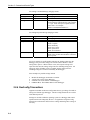
2.3.5 Get/Set Values Transaction (MsgType 0x1a, 0x9a, 0x1b, &
0x9b)
These transactions are used to read or write values in the datalogger table.
Values are referenced by table and field name. The table definitions can be
used to get table and field names from a datalogger if they are not known.
Get Values Command Body (MsgType 0x1a):
Name
MsgType
TranNbr
Security Code
TableName
TypeCode
Type
Byte
Byte
UInt2
ASCIIZ
Byte
FieldName
ASCIIZ
Swath
UInt2
Description
Message type code (0x1a)
Transaction number
Security code of the datalogger
Table name
Data type code that specifies the format of the
data values returned in the response
Field name including dimensionality if
applicable
Number of values to get starting with the one
specified by FieldName
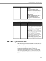
Get Values Response Body (MsgType 0x9a):
Name
MsgType
TranNbr
RespCode
Type
Byte
Byte
Byte
{ Values }
Byte [ ]
Description
Message type code (0x9a)
Transaction number
Response code:
0x00: Complete
0x01: Permission denied
0x10: Invalid table or field
0x11: Data type conversion not supported
0x12: Memory bounds violation
Values from the datalogger repeated as needed
according to the Swath. The TypeCode and the
number of elements requested determine the
size of this field.
2-23
Section 2. Protocols and Packet Types
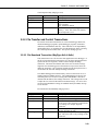
Set Values Command Body (MsgType 0x1b):
Name
MsgType
TranNbr
SecurityCode
TableName
TypeCode
Type
Byte
Byte
UInt2
ASCIIZ
Byte
FieldName
ASCIIZ
Swath
UInt2
{ Values }
Byte [ ]
Description
Message type code (0x1b)
Transaction number
Security code of the datalogger
Table name
Data type code that specifies the format of the
data values returned in the response
Field name including dimensionality if
applicable
Number of values to set starting with the one
specified by FieldName
Values to set in the datalogger repeated as
needed according to the Swath. The TypeCode
and the number of elements requested
determine the size of this field.
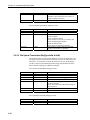
Set Values Response Body (MsgType 0x9b):
Name
MsgType
TranNbr
RespCode
Type
Byte
Byte
Byte
Description
Message type code (0x9b)
Transaction number
Response code:
0x00: Complete
0x01: Permission denied
0x10: Invalid table or field
0x11: Data type conversion not supported
0x12: Memory bounds violation
Since dealing with data types can be a complex process in these transactions,
the client application will dictate the data type. On a Get Values transaction
the datalogger must convert the values to the data type requested. On a Set
Values transaction, the datalogger must convert the values to the appropriate
internal data type. If a conversion is not supported or not possible, the
response will indicate this lack of support appropriately.
2-24
Section 3. The CR200 Datalogger
The CR200 is low-cost, rugged, and versatile measurement device. This small datalogger
contains a CPU and both digital and analog inputs and outputs. The CR200 has a PakBus
operating system that communicates via the BMP5 message protocol. Pre-compiled
programs sent to the datalogger are written in a BASIC-like language that includes data
processing and analysis routines. These programs run on a precise execution interval and
will store measurements and data in tables.
The CR200 has a built in RS-232 port allowing a direct connection from a PC. Once the
PC has established a connection to the datalogger, the application running on the PC can
communicate directly to the datalogger. Unlike other dataloggers the CR200 does not
have security available in the operating system. Since a security code cannot be set in the
CR200, the SecurityCode field prevalent in many of the BMP5 protocol message bodies
can remain null.
3.1 Dealing with Unexpected, Asynchronous
Commands from the CR200
Communication on a packet switched network occurs asynchronously.
Therefore, an application must not expect response packets from the datalogger
in any particular order. Careful attention to each transaction number and
message type will help eliminate confusion with packets that are received by
the application. In addition, the DstPhyAddr value in the header of each
received packet should match the application’s advertised address or the packet
should be discarded.
There also may be packets and message types periodically sent across the
network that aren’t detailed in this document. This document attempts to
describe the critical message types necessary to facilitate communication. If
the application receives any packets from a datalogger that haven’t been
discussed in this documentation, the application should respond with a PakCtrl
Delivery Failure Message (Packet Type 0x81) specifying that the command is
not currently implemented or understood by the application.
3.2 Getting the Attention of the Datalogger
The application should initiate communication with the datalogger by using a
SerPkt Link-state “Ring” transaction. The datalogger will return a SerPkt
Link-state “Ready” packet to let the application know to proceed with
communication. Although the initial Ring and Ready packets should be used,
they are not required. If the PakBus address of the datalogger is known, the
application can send any appropriate message to the datalogger at anytime.
An example of a “Ring” packet from an application with a PakBus address of
4094 to a datalogger with a PakBus address of 1 to request the communication
link state is as follows:
BD 90 01 0F FE 71 D2 BD
3-1
Section 3. The CR200 Datalogger
An example of a “Ready” response from a datalogger with an address of 1 to
an application with an address of 4094 letting the application know it can
proceed with communication is as follows:
BD AF FE 00 01 5A 89 BD
The datalogger may not be aware that a connection has been established from
the PC when beginning the initial communication process. The application
should initiate communication to the CR200 by sending a series of 0xbd
SerSyncBytes to wake up the datalogger and clear the communication buffer.
The CR200 series datalogger only supports connections at 9600 baud.
3.3 Getting the PakBus Address of the CR200
The address of the CR200 datalogger is necessary for communication. Every
PakBus device needs a PakBus address to send and receive packets. In
addition all devices on the network require unique addresses. The valid range
for PakBus addresses is 1 to 4094. The address range of 1 to 3999 is normally
reserved for dataloggers while the address range of 4000 to 4094 is normally
reserved for applications. The CR200 ships with a default PakBus address of 1
but could have any address within the allowable range.
If the address of the CR200 datalogger is unknown, this information can be
obtained with a PakCtrl Hello Request Message. Since all PakBus dataloggers
on the network will respond to this broadcast type message, make sure you are
connected to a single datalogger before you send a PakCtrl Hello Request
Message in order to determine that specific datalogger’s address.
The DstPhyAddr and DstNodeId in the header of the Hello Request Message
should be specified as 4095 to indicate a broadcast packet. The datalogger will
respond to the application with a Hello Command transaction that contains its
PakBus address in the header.
3.4 Getting and Setting CR200 Settings
The settings within the CR200 datalogger are obtained with the Get Settings
transaction. Similarly the CR200 settings can be set with the Set Settings
transaction. The CR200 uses datalogger settings much like a personal computer
uses environmental variables.
Datalogger settings exist as ASCII strings in the CR200. They are returned to
the application in a response message as a string containing a list of namevalue pairs with each name separated by the value with the “=” sign. Each
value-pair is also separated with a semi-colon. For example:
Model=CR200;PakBusAddress=1
Some examples of available CR200 settings include:
3-2
•
Model: The datalogger model name or number
•
Version: The version of the datalogger
•
SerialNbr: The serial number of the datalogger
Section 3. The CR200 Datalogger
•
PakBusAddress: The PakBus address of the datalogger
If the names of the available settings are not known, all settings within the
CR200 datalogger can be obtained by specifying a null NameList parameter in
a Get Settings transaction. Once the settings are returned, they can be parsed,
viewed, and later used as needed.
3.5 Getting and Setting the CR200 Clock
The CR200 datalogger contains an accurate clock that drives the execution
interval of the running datalogger program. An application can either check or
set the datalogger clock with the Clock Transaction.
Before attempting to set the datalogger clock, the application should always
check the current time. Then, if necessary, the appropriate adjustment can be
made by either adding time to or subtracting time from the datalogger clock
with the Clock Command message. A hexadecimal example of this message
that is checking the clock for a datalogger with a PakBus address of 1 looks
like:
BD A0 01 4F FE 10 01 0F FE 17 17 00 00 00 00 00 00 00 00 00
00 B2 B3 BD
The response from the datalogger to the clock request comes in the form of the
Clock Response message. A hexadecimal example of a clock response packet
looks like:
BD AF FE 00 01 1F FE 00 01 97 17 00 1B FA 2A 61 C8 00 00 00
04 FA BD
3.6 Datalogger Program Structure
CR200 programs are written with a programming language called CRBasic.
This BASIC-like programming language syntax facilitates the creation of
datalogger programs capable of precise measurement and data analysis.
Datalogger programs declare variables, define tables to store data, and run
instructions to make measurements or process information.
Datalogger programs that are sent to the datalogger execute on a precise
interval to process data or make measurements. Data are stored in tables
defined by the datalogger program. By default, all CR200 dataloggers include
the Status table and the Public table. The Status table contains information
about the datalogger operating system and parameters. The Public table
contains program variables and measurements. A maximum of four additional
custom tables can be defined in the datalogger program and used to store data
in the CR200.
When the datalogger runs the compiled program, the defined tables are created
in Flash memory. As the program executes, data are stored in the created
tables on the specified interval. Therefore, when the datalogger is powered
down, the data remains. However, since the datalogger program creates the
tables, all data are erased when a new datalogger program is sent to the
datalogger.
3-3
Section 3. The CR200 Datalogger
3.7 Creating CR200 Programs and the CR200
Compiler
The CR200 datalogger must contain a valid program in order to execute
instructions that measure and analyze sensor data. These programs are usually
generated with either a software program called Short Cut for Windows or with
a program editor called CRBasic Editor but if the correct syntax is used,
datalogger programs can be written with any text editor.
Because of the compact size of the CR200, only compiled programs can be
sent to the datalogger. Once a program has been created, it must be compiled
to match the operating system of the datalogger before being sent to the
CR200. If program compiler does not match the current operating system on
the datalogger, the compiled program will be rejected.
Appropriate compilers are included with both Short Cut for Windows and the
CRBasic Editor. Once an application discovers the operating system version of
the CR200, the appropriate compiler can be used to compile a program before
sending it to the datalogger. When a program is sent to the datalogger, the
datalogger response will indicate if a compiler compatibility problem exists.
Attempts should be made to use the most recently released operating system in
the CR200. However, if the program compiler and the datalogger operating
system are not compatible, either the program must be recompiled with the
correct compiler or the datalogger operating system must change to match the
compiled program. Since there is not a an easy way to know what compiler
was used on the datalogger program, the recommended resolution is to
discover the operating system version of the CR200 and recompile the
datalogger program with the corresponding compiler.
3.7.1 Discovering the CR200 OS Version
There are two methods of discovering the CR200 operating system version.
The first method is to use the File Control Get Programming Statistics
transactions to query the datalogger for this information. The datalogger
operating system information will be included in the response message.
The second method is to get table definitions and then collect data from the
Status table of the CR200. The Status table holds key information like the
datalogger operating system version. However, if a program isn’t running on
the datalogger, table definitions will not be available and the Status table
cannot be queried. Therefore, the better option may be to focus on getting the
OS version using the Get Programming Statistics transaction.
Compare the discovered CR200 series datalogger operating system version to
the compiler used to create the datalogger program. For example, if the
datalogger reports an operating system of “v03A”, the appropriate compiler
would be named “cr2compv03A.exe”. Remember that the program must be
compiled to match the operating system running on the datalogger.
3-4
Section 3. The CR200 Datalogger
3.7.2 Sending a Program to the CR200
The compiled datalogger program is sent to the CR200 with the File Download
transaction. The FileName parameter of this transaction describes the file
name and location in datalogger memory where the datalogger program should
be stored. The compiled datalogger program will always have an extension of
“.bin”. An example of the FileName parameter is “CPU:CR200Program.bin”.
In addition, the attributes of the file should be specified. With the CR200 the
only file attribute to consider when sending the datalogger program is run now
since the compact size of the datalogger disallows the storage of old programs
or files.
The compact buffer size of the CR200 requires that the application not send a
packet that exceeds 100 bytes including the header. If the datalogger program
being sent exceeds this maximum size, the message must be broken across
multiple packets. The complexity of sending a program to the datalogger is
shown in the following diagram.
3-5
Section 3. The CR200 Datalogger
3-6
Section 3. The CR200 Datalogger
Use the File Control Command with a FileCmd parameter of 0x08 to stop the
program currently running on the datalogger.
Check the File Control Response. If the RespCode returns a zero, determine
the amount of time to wait as declared in the HoldOff parameter before
continue the process. Otherwise, report and act on the error result.
Use the File Download Command message to send the new program file to the
datalogger. The new program file must have the “.BIN” file extension.
Usually the new program is larger than the 100-byte MaxPktSize of the CR200
datalogger so it should be separated into packets that will fit into the
MaxPktSize. After sending each packet, the application should check the
RespCode and FileOffset parameters for errors. The file download operation
should stop immediately if an error occurs and the error should be handled. If
a response is not received, the application can retry the same packet. If there
are no problems, the packets should be sent in sequential order to the
datalogger.
Use the File Control Command with the FileCmd parameter set to 1 to run the
new program on the datalogger. Since the CR200 series datalogger does not
contain a file system that allows storage of old programs or files, the only
option really available at this step is to run the current program.
Check the File Control Response. If the RespCode returns a zero, determine
the amount of time to wait as declared in the HoldOff parameter before
continuing the process. Otherwise, report and act on the error message.
Finally, use the Get Programming Statistics transaction and obtain compile
results to verify the new datalogger program information.
3.7.3 Interpreting the Response
After the compiled datalogger program has been sent, the application should
receive a File Download Response message. The response code within this
message indicates what action the application should attempt next. Possible
response codes include: complete (0x00), permission denied (0x01),
insufficient resources or memory full (0x02), invalid fragment number (0x09),
invalid file name (0x0d), and file is not currently accessible (0x0e).
3.7.4 Handling Rejection
When everything goes as planned, the datalogger indicates the program was
sent successfully with a response code of complete (0x00). However, if a
problem occurs when sending a program, the datalogger will indicate the
nature of the problem with the appropriate response code.
There have been cases where a “permission denied” message has been received
from the CR200. Since security can not be enabled on the CR200, this
message actually indicates that the Swath parameter of the requested packet
exceeds the maximum PakBus packet size of 1000 bytes. The application
should not request a packet size larger than the maximum from the datalogger
in the Swath parameter of the File Upload Command message.
Finally, the application must determine how long to wait before discarding a
transaction and retrying the packet with a new transaction number when a
command has been sent but a response hasn’t been received. The expected
3-7
Section 3. The CR200 Datalogger
latency varies across different communication mediums but the application
should be aware of this variability and set the maximum retry interval
accordingly.
3.8 Understanding Table Definitions and Table
Signatures
Since the CR200 stores data in tables, the datalogger and the application must
understand and agree on the structure of each table in order to collect data.
Table definitions contain the parameters that describe each table, record, and
field in the datalogger. These parameters exist on the datalogger in a file with
a “.TDF” extension. Obtain table definitions from the datalogger using the File
Upload transaction requesting a file named “.TDF”.
Table definitions are used by the application to know what tables and fields
exist and what data to expect from each table when collecting values from the
CR200. In order to ensure the integrity of this table information, the
application should calculate a signature of the parameters contained in each
table within the table definitions. One signature should be calculated for each
defined table and should be stored and used by the application to verify that the
table has not changed when collecting data.
3.9 Getting Table Definitions from the CR200
Table definitions are retrieved from the CR200 with the File Upload
transaction before attempting data collection. The file name in the transaction
should be specified as “.TDF”. The datalogger recognizes this file extension
and returns the appropriate response containing the table definitions. A
hexadecimal example of the command looks like:
BD A0 01 70 04 10 01 00 04 1D 1D 00 00 43 50 55 3A 44 65 66
2E 74 64 66 00 00 00 00 00 00 00 80 27 EA BD
The response message from the datalogger contains the table definitions and
may be broken over multiple packets. A function should be created that parses
the table information from the response packet. This information should be
used by the application to calculate table signatures and to interpret data
records that are collected from the datalogger. If the table definitions are
broken over multiple packets, the last File Upload Response packet should
have a value in the FileOffset field that is smaller than the Swath field declared
in the File Upload Command packet. An example response packet looks like:
BD
74
00
00
61
00
00
69
A0
75
00
00
74
00
01
67
04
73
00
00
65
00
00
00
00
00
00
01
00
00
00
00
01
00
00
00
00
8B
00
F1
10
00
8B
00
00
50
10
67
04
00
4F
00
00
72
00
BD
00
01
53
08
00
6F
00
01
0C
76
00
00
67
00
9D
00
65
00
00
4E
10
1D
00
72
00
00
61
00
00
00
73
08
01
6D
00
00
00
69
00
00
65
00
00
00
6F
00
00
00
00
00
00
6E
00
00
00
95
00
00
00
00
0A
00
50
01
00
00
8B
00
00
72
53
00
00
4F
00
00
6F
74
00
00
53
00
00
67
3.9.1 How to Get and Use Table Signatures
The table definition signature is a signature for the parameters describing a
table. There must be one signature for each defined table in the File Upload
3-8
61
00
00
44
0A
00
53
Section 3. The CR200 Datalogger
Response packet. Calculate the signature by starting with the first byte of the
FieldName parameter and ending after the field list terminator for that table. A
description of the signature algorithm and example C code showing the method
used to calculate the signature can be found in Appendix B. Additional
examples showing functions used to parse tables from table definitions and
calculate signatures existing in the JAVA code found in Appendix D.
The table signature should be stored by the application and used in the Collect
Data Command packet when collecting data from the CR200. The datalogger
validates the table signature and ensures that the datalogger tables have not
changed when an application requests data.
Please note that table definitions and table signatures are not specifically
required if the table structure is known and the application uses the Get Values
or Set Values transaction. These transactions only require specific table
information and do not use a table signature.
3.10 Retrieving Data from the CR200
By default data are stored in ring memory on the datalogger and must be
collected by an external application before the old values are overwritten by
new values. One way an application retrieves this data is with the Collect Data
transaction. An example packet that initiates the collection process looks like:
BD A0 01 70 04 10 01 00 04 09 09 00 00 05 00 03 43 15 00 00
00 3C 00 00 C7 DF BD
The response packet from the datalogger will contain data that must be parsed.
The application uses table definition information to understand the data
structure in the packet in order to extract the appropriate information from the
response packet.
3.10.1 Interpreting Data Types
The data type determines how each value should be handled by the application.
The Appendix includes some of the data types that might be encountered when
collecting data from or sending data to a CR200.
3.10.2 Data Collection Sequence
The following steps should be used when collecting data from the CR200:
1.
Get the current table definitions if necessary by using the File Upload
transaction.
2.
If table definitions are returned, parse the table information from the
response packet. This information should be saved and used to interpret
collected data records. The table signature should also be calculated and
used when requesting data from the datalogger.
3.
Use the Collect Data Transaction to initiate data collection from the
CR200 and parse the data contained in the Collect Data Response packet.
3-9
Section 3. The CR200 Datalogger
3.10.3 Collecting Tables and Specific Records
Within the Collect Data Command message there are many options for data
collection. The CollectMode parameter of this packet describes what records
will be collected from the defined tables. Some collect mode options include:
3-10
CollectMode 0x03: Collect from the oldest record to the newest record
starting with the oldest data in each table. This method of collection
would be used to collect entire data tables.
CollectMode 0x04: Collect from a defined record to the newest record in
the tables defined. If the defined starting record doesn’t exist in the
datalogger, data collection will start from the oldest record in the table.
CollectMode 0x05: Collect the most recent records, where the number of
records to collect is a definable parameter.
CollectMode 0x06: Collect from a defined record up to but not including a
second defined record. This method of collection would be useful to
collect a specific subset of records from the datalogger.
Section 3. The CR200 Datalogger
3.10.4 Getting Values from Specific Records
Use either the Collect Data Command or the Get Values transaction when
attempting to collect a specific value or swath of values from an individual
record. These values are referenced by the table and field name, which can be
found in the table definitions collected from a station if the user does not
already know them. The Collect Data Command allows multiple fields to be
specified while the Get Values transaction focus on a single field at a time.
Once the table and field names are known the Collect Data or Get Values
Command packet can be sent to the datalogger specifying the exact values that
are wanted. The Collect Data or Get Values Response packet returns the
values requested or if an error occurs, the error is specified but no values are
returned.
These transactions are designed to minimize complexity, by allowing the
application to dictate the data type of the values that are returned. On a Collect
Data or Get Values transaction, the datalogger must convert the data value to
the data type requested. If the datalogger does not support a requested data
type or the conversion is not possible, the response will indicate that the data
type conversion is not supported. In general, the safest data type to request is
IEEE4.
3.11 Controlling Packet Size
Because of the compact size of the CR200, it has a limited buffer space for
receiving packets. Therefore, an application should not send messages to the
datalogger that exceed 100 bytes including the header. This maximum packet
size information can be obtained from the datalogger if necessary via the Get
Settings transaction. The setting containing this information is named
“MaxPktSize”.
Additionally, the application must not request packets from the datalogger that
exceed the 1000 byte PakBus message limit. The requested number of bytes
from the CR200 datalogger should always be less than this maximum size to
stay within the limits of the CR200 datalogger and the PakBus message limit.
3-11
Section 3. The CR200 Datalogger
This is a blank page.
3-12
Section 4. The CR1000 Type Datalogger
The CR1000 type datalogger (CR1000, CR3000, and CR800) is a rugged and versatile
measurement device. This datalogger contains a CPU and both digital and analog inputs
and outputs. The CR1000 type datalogger uses a PakBus operating system and
communicates with applications via the BMP5 message protocol. Programs sent to the
datalogger are written in a BASIC-like language that includes data processing and
analysis routines. These programs run on a precise execution interval and will store
measurements and data in tables.
4.1 Dealing with Unexpected Commands
Since communication with a CR1000 type datalogger is packet based, chances
are an application will receive unexpected or asynchronous commands from
the datalogger. The response packet received may or may not be related to the
last command packet sent by the application or may not even be destined for
the application. Transaction numbers generated by the application and
included in the command message are one way to track appropriate responses.
By identifying the message type and knowing the transaction number, response
packets can be appropriately handled by the application. In addition, the
application should ignore messages that have a DstPhyAddr value in the packet
header that is different than the address being used by the application.
An application may also periodically receive packets from the datalogger that
weren’t requested but which need a response. For example, the datalogger may
send out a Hello transaction to which the application should respond. If the
application receives a command packet and does not respond, the datalogger
will continue to send command packets until the application answers
appropriately. If the application receives any packets from a datalogger that
haven’t been discussed in this documentation, the application should respond
with a PakCtrl Delivery Failure Message (Packet Type 0x81) specifying that
the command is not currently implemented or understood by the application.
4.2 Getting the Attention of the Datalogger and
Establishing a Baud Rate
The application should initiate communication with the datalogger by using a
SerPkt Link-state “Ring” transaction. The datalogger will return a SerPkt
Link-state “Ready” packet to let the application know to proceed with
communication. Although the Ring and Ready packets should be used, they
are not required. If the PakBus address of the datalogger is known, the
application can send any appropriate message to the datalogger at anytime.
The following is an example “Ring” packet from an application with a PakBus
address of 4094 sent to a datalogger with a PakBus address of 1 to determine
the communication link state:
BD 90 01 0F FE 71 D2 BD
The following is a corresponding example of a “Ready” response from a
datalogger with an address of 1 to an application with an address of 4094
letting the application know it can proceed with communication:
4-1
Section 4. The CR1000 Type Datalogger
BD AF FE 00 01 5A 89 BD
The datalogger may not be aware that a connection has been established from
the PC when beginning the initial communication process. The application
should initiate communication to the CR1000 by sending a series of 0xbd
SerSyncBytes before the initial packet to wake up the datalogger, clear the
communication buffer, and determine the communication baud rate.
Since the CR1000 type datalogger supports automatic baud-rate
synchronization, the recommended procedure is to send at least six
SerSyncBytes before sending the Ring packet.
4.3 Getting the PakBus Address
Knowing the address of the CR1000 type datalogger is necessary for
communication. Every PakBus device needs a PakBus address to send and
receive packets. In addition all devices on the network need unique addresses.
The valid range for PakBus addresses is 1to 4094. The address range of 1 to
3999 is normally reserved for dataloggers while the address range of 4000 to
4094 is normally reserved for applications. The CR1000 type datalogger ships
with a default PakBus address of 1 but could have any address within the
allowable range.
If the address of the CR1000 type datalogger is unknown, it can be obtained
with a PakCtrl Hello Request Message. Since all PakBus dataloggers on the
network will respond to this broadcast type message, make sure you are
connected to a single datalogger before you send a PakCtrl Hello Request
Message in order to determine that specific datalogger’s address.
The DstPhyAddr and DstNodeId in the header of the Hello Request Message
should be specified as 4095 to indicate a broadcast packet. The datalogger will
respond to the application with a Hello Command transaction that contains its
PakBus address in the header.
4.4 Getting and Setting Datalogger Settings
The DevConfig protocol is used to get settings from and set setting on the
CR1000 type datalogger. The DevConfig Get Settings transaction is used to
request specific settings from the datalogger according to the setting ID.
Similarly the setting ID is used with the DevConfig Set Settings transaction
when attempting to change a particular setting on the datalogger.
In both of these cases, the setting ID used comes from the Device Description
File for the CR1000 datalogger found in Appendix C. This XML file contains
setting ID catalogs corresponding to specific operating system versions for the
CR1000 type datalogger. Since parsing this XML file may be difficult,
viewing the file and merely including the necessary settings with a
corresponding ID in the application is an acceptable method for getting settings
from and setting settings in a CR1000 type datalogger.
Settings are specific to the operating system of the CR1000 type datalogger.
An example of some common settings for CR1000 type datalogger operating
systems are taken from the Device Description File in Appendix C include but
are not limited to those described in the following table. Discover additional
4-2
Section 4. The CR1000 Type Datalogger
settings for this and other operating systems by reviewing the included Device
Description File in Appendix C.
Setting ID
0
1
2
3
4
Name
OS Version
Serial Number
Station Name
PakBus Address
Security
4.5 Getting and Setting the Clock
The CR1000 type datalogger contains a precise clock that drives the execution
interval of the running program. An application can either check or set the
datalogger clock with the Clock Transaction.
Before attempting to set the datalogger clock, the application should always
check the current time. Then, if necessary, the appropriate adjustment can be
made by either adding time to or subtracting time from the datalogger clock
with the Clock Command message. A hexadecimal example of this message
that is checking the clock for a datalogger with a PakBus address of 1 looks
like:
BD A0 01 4F FE 10 01 0F FE 17 17 00 00 00 00 00 00 00 00 00
00 B2 B3 BD
The response from the datalogger to the clock request comes in the form of the
Clock Response message. A hexadecimal example of a clock response packet
looks like:
BD AF FE 00 01 1F FE 00 01 97 17 00 1B FA 2A 61 C8 00 00 00
04 FA BD
4.6 The Program Structure
CR1000 type datalogger programs are written with a programming language
called CRBasic. This BASIC-like programming language facilitates the
creation of datalogger programs capable of precise measurement and data
analysis. Programs are sent to the CR1000 type datalogger as ASCII text
where the datalogger operating system compiles and runs them.
Datalogger programs execute on a precise interval to process data or store
measurements. Data are stored in tables that are defined by the datalogger
program. The CR1000 type datalogger includes the Status table and the Public
table by default. The number of additional tables that can be defined by the
datalogger program is only limited by the amount of memory available in the
datalogger.
The CR1000 type datalogger compiles the program and creates tables that are
stored in battery backed RAM. Therefore, when the datalogger is powered
down, the data remains. However, since the datalogger program creates the
tables, all data are erased when a new datalogger program is compiled and run
by the datalogger.
4-3
Section 4. The CR1000 Type Datalogger
4.7 Sending a Program to the Datalogger
The CR1000 type datalogger accepts text programs written with CRBasic
syntax and automatically compiles these programs before running them. As
long as the program contains correct CRBasic syntax, the datalogger should
compile and run the program.
Use the File Download transaction to send the program from the application to
the datalogger. The file name and device memory location must be specified.
Possible locations for storing files in the CR1000 type datalogger include CPU,
USR, and CRD.
The CR1000 type datalogger looks at the file extension provided with the file
name and attempts to compile the program appropriately. For example, a file
name of “CPU:ProgName.CR1” will be compiled as a new datalogger program
in datalogger memory. Possible file extensions include “.CR1”, which
designates a datalogger program and “.OBJ”, which designates a datalogger
operating system.
The complexity of sending a program to the datalogger is shown in the
following diagram.
4-4
Section 4. The CR1000 Type Datalogger
Use the File Download Command message to send the new program file to the
datalogger. The new program file must have the “.CR1” file extension. If the
program is larger than the MaxPktSize of the datalogger, it should be separated
into packets that will fit into the MaxPktSize. After sending each packet, the
application should check the RespCode and FileOffset parameters for errors.
The file download operation should stop immediately if an error occurs and the
error should be handled. If a response is not received, the application can retry
the same packet. If there are no problems, the packets should be sent in
sequential order to the datalogger.
Send a File Control Command with the FileCmd parameter set to “0x0d” or
“0x0e” to specify the name of the new program, stop the old program, delete its
4-5
Section 4. The CR1000 Type Datalogger
files, and start the new program on the datalogger. Check the File Control
Response. If the RespCode returns a zero, determine the amount of time to
wait as declared in the HoldOff parameter and wait at lest that amount of time
before continuing the process. Otherwise, report and act on the error message.
Send the Get Programming Statistics transaction and obtain compile results to
verify the new datalogger program information. Since the datalogger is
compiling the program and allocating table space, the application may need to
wait for this response. The datalogger will send a Please Wait message if a
delay is going to occur.
Once the application verifies that the datalogger has properly compiled and is
running the new program, table definitions can be retrieved and used by the
application.
4.7.1 Interpreting the Response
After the datalogger program has been sent to the CR1000 type datalogger, the
application should anticipate a File Download Response message. The
response code within this message indicates the next action the application
should attempt. Possible response codes include: complete (0x00), permission
denied (0x01), insufficient resources or memory full (0x02), invalid fragment
number (0x09), invalid file name (0x0d), and file is not currently accessible
(0x0e).
4.7.2 Handling Rejection
When everything goes as planned, the datalogger indicates the program was
sent successfully with a response code of “complete”. However, if a problem
occurs when sending a program, the datalogger will indicate the nature of the
problem with a different response code.
For example, a “permission denied” message indicates that security is enabled
on the CR1000 type datalogger and an improper security code has been sent to
the datalogger. The application should prompt for and send the correct security
code. Additionally, the CR1000 type datalogger can store multiple programs
and files so an “insufficient resources or memory full” response code requires
the application to use the File Control transaction to remove existing programs
or files and make room for the new program.
Finally, the application must determine how long to wait before discarding a
transaction and retrying the packet with a new transaction number when a
command has been sent but a response hasn’t been received. The expected
latency varies across different communication mediums but the application
should be aware of this variability and set the maximum retry interval
accordingly.
4.7.3 Erasing Files on the CFM100
The CompactFlash™ Module of the CR1000 and CR3000 provides additional
storage for data, programs, and files. The File Control transaction can
administer and delete files from the CFM100 in the same manner as deleting
files from datalogger memory but by specifying a file and location on the
memory card instead of a file and location in the datalogger memory.
4-6
Section 4. The CR1000 Type Datalogger
4.7.4 Deleting Program Files
When loading a new datalogger program to the CR1000 type datalogger, the
old datalogger program can remain in datalogger memory for future use or
reference. Although data tables are recreated and the data for the currently
running program will be lost when a new program begins running on the
datalogger, the old program does not have to be deleted. However, if the
datalogger memory becomes too full or if the old program is no longer needed
the File Control transaction provides a method of deleting files either when
sending a new program to the datalogger or as an independent transaction. The
FileCmd codes in the File Control transaction include the following options:
0x01: Compile and run the new program
0x02: Toggle the “run on power-up” option on the datalogger program
specified
0x03: Make the specified file hidden so it cannot be downloaded or
viewed.
0x04: Delete the specified file
0x05: Format the datalogger
0x06: Compile and run the program without deleting data tables
0x07: Stop the running program
0x08: Stop the running program and delete all associated files
0x09: Make the specified file the new operating system
0x0a: Compile and run the program without changing the “run on powerup” file
0x0b: Pause execution of the running program
0x0c: Resume execution of the running program
0x0d: Stop the running program, delete associated files, and run the
specified program while marking it as the “run on power-up” program
0x0e: Stop the running program, delete associated files, and run the
specified program without changing the “run on power-up” attribute
The CR1000 type datalogger can store files in memory for future use or
retrieval. If the files contained on the CR1000 type datalogger are not known,
obtain a list of the files by requesting a file named “.DIR” with the File Upload
transaction. Once the list of files has been retrieved, use the File Control
transaction to make necessary changes to the files or file attributes.
4.8 Understanding Table Definitions and Table
Signatures
Since the CR1000 type dataloggers store data in tables, the datalogger and the
application must understand and agree on the structure of each table in order to
collect data. Table definitions contain the parameters that describe each table,
record, and field in the datalogger and are contained in a file on the datalogger
with a “.TDF” extension. This file is obtained from the datalogger using the
File Upload transaction.
Table definitions are used by the application to know what tables and fields
exist and what data to expect from each table when collecting values from the
CR1000 type datalogger. In order to ensure the integrity of this table
information, the application should calculate signatures for the tables within
the table definitions. One signature should be calculated for each defined table
and should be stored and used by the application to verify that the table has not
changed when collecting data.
4-7
Section 4. The CR1000 Type Datalogger
4.9 Getting Table Definitions
Table definitions are retrieved from the CR1000 type datalogger with the File
Upload transaction. The file name in the transaction should be specified as
“.TDF”. The datalogger will recognize this file extension and return the
appropriate response containing the table definitions. A hexadecimal example
of the command packet looks like:
BD A0 01 70 04 10 01 00 04 1D 1D 00 00 43 50 55 3A 44 65 66
2E 74 64 66 00 00 00 00 00 00 00 80 27 EA BD
The response message from the datalogger will contain the table definitions
and may be broken over multiple packets. A function should be created to
parse the table information from the response packet. This information should
be saved by the application and used to calculate table signatures and to
interpret data records that are collected from the datalogger. If the table
definitions are broken over multiple packets, the last File Upload Response
packet should have a value in the FileOffset field that is smaller than the Swath
field declared in the File Upload Command packet. An example response
packet looks like:
BD
74
00
00
61
00
00
69
A0
75
00
00
74
00
01
67
04
73
00
00
65
00
00
00
00
00
00
01
00
00
00
00
01
00
00
00
00
8B
00
F1
10
00
8B
00
00
50
10
67
04
00
4F
00
00
72
00
BD
00
01
53
08
00
6F
00
01
0C
76
00
00
67
00
9D
00
65
00
00
4E
10
1D
00
72
00
00
61
00
00
00
73
08
01
6D
00
00
00
69
00
00
65
00
00
00
6F
00
00
00
00
00
00
6E
00
00
00
95
00
00
00
00
0A
00
50
01
00
00
8B
00
00
72
53
00
00
4F
00
00
6F
74
00
00
53
00
00
67
61
00
00
44
0A
00
53
4.9.1 How to Get and Use Table Signatures
The table definition signature is a signature on the parameters describing a
table. There must be one signature for each defined table in the File Upload
Response packet. Calculate the signature by starting with the first byte of the
FieldName parameter and ending after the field list terminator for that table. A
description of the signature algorithm and example C code showing the method
used to calculate the signature can be found in Appendix B. Additional
examples showing functions used to parse tables from table definitions and
calculate signatures existing in the JAVA code found in Appendix D.
The table signature should be stored by the application and used in the Collect
Data Command packet when collecting data from the CR1000 type datalogger.
The datalogger validates the table signature to ensure that the datalogger tables
have not changed when an application requests data.
4.10 Retrieving Data
By default data are stored in ring memory on the datalogger and must be
collected by an external application before the old values are overwritten by
new values. The data are stored in tables in the CR1000 type datalogger and an
application retrieves this data using the Collect Data transaction. An example
of a packet that initiates the collection process looks like:
BD A0 01 70 04 10 01 00 04 09 09 00 00 05 00 03 43 15 00 00
00 3C 00 00 C7 DF BD
4-8
Section 4. The CR1000 Type Datalogger
The response packet from the datalogger will contain data that must be parsed.
The application uses table definition information to understand the data
structure in the packet in order to extract the appropriate information from the
response packet.
4.10.1 Interpreting Data Types
The data type determines how each value should be handled by the application.
The Appendix includes a table for some of the data types that might be
encountered when collecting data from or sending data to a CR1000 type
datalogger.
4.10.2 Data Collection Sequence
The following steps should be used when collecting data from the CR1000 type
datalogger:
Get the current table definitions if necessary by using the File Upload
transaction.
When table definitions are returned, parse the table information from the
response packet. This information should be saved and used when collecting
data records. Each table signature should be calculated, saved, and then used
when requesting data from the datalogger.
Use the Collect Data Transaction to initiate data collection from the CR1000
type datalogger and parse the data contained in the Collect Data Response
packet.
4.10.3 Collecting Tables and Specific Records
Within the Collect Data Command message there are many options for data
collection. The CollectMode parameter of this packet describes what records
will be collected from the defined tables. Some collect mode options include:
CollectMode 0x03: Collect from the oldest record to the newest record
starting with the oldest data in each table. This method of collection
would be used to collect entire data tables.
CollectMode 0x04: Collect from a defined record to the newest record in
the tables defined. If the defined starting record doesn’t exist in the
datalogger, data collection will start from the oldest record in the table.
CollectMode 0x05: Collect the most recent records, where the number of
records to collect is a definable parameter.
CollectMode 0x06: Collect from a defined record up to but not including a
second defined record. This method of collection would be useful to
collect a specific subset of records from the datalogger.
4-9
Section 4. The CR1000 Type Datalogger
4.10.4 Getting Values from Specific records
Use either the Collect Data Command or the Get Values transaction when
attempting to collect a specific value or swath of values from an individual
record. These values are referenced by the table and field name, which can be
found in the table definitions collected from a station if the user does not
already know them. The Collect Data Command allows multiple fields to be
specified while the Get Values transaction focus on a single field at a time.
Once the table and field names are known the Collect Data or Get Values
Command packet can be sent to the datalogger specifying the exact values that
are wanted. The Collect Data or Get Values Response packet returns the
values requested or if an error occurs, the error is specified but no values are
returned.
These transactions are designed to minimize complexity, by allowing the
application to dictate the data type of the values that are returned. On a Collect
Data or Get Values transaction, the datalogger must convert the data value to
the data type requested. If the datalogger does not support a requested data
type or the conversion is not possible, the response will indicate that the data
type conversion is not supported. In general, the safest data type to request is
IEEE4.
4-10
Section 4. The CR1000 Type Datalogger
4.11 Collecting Files from the Datalogger
The CR1000 type datalogger can store files in memory for future use or
retrieval. The list of files contained in datalogger memory can be obtained by
requesting a file name of “.DIR” with the File Upload transaction. The
datalogger responds with a list of files that are stored on the datalogger. After
obtaining the directory listing of files that exist on the datalogger, use the File
Upload transaction to retrieve a specific file from the datalogger.
4.12 Controlling Packet Size
In order to stay within the maximum allowed packet size for the PakBus
protocol, an application must not request packets from the datalogger that
exceed the 1000 byte message size limit. The requested number of bytes from
the datalogger should always be less than this maximum size including the
header information in order to stay within the limits of the datalogger and
PakBus message limit.
4-11
Section 4. The CR1000 Type Datalogger
This is a blank page.
4-12
Appendix A. Data Types Summary
Name
Byte
UInt2
UInt4
Int1
Int2
In4
FP2
FP3
FP4
IEEE4B
IEEE8B
Bool8
Bool
Bool2
Bool4
Sec
Code
1
2
3
4
5
6
7
15
8
9
18
17
10
27
28
12
Size
1
2
4
1
2
4
2
3
4
4
8
1
1
2
4
4
USec
13
6
NSec
14
8
ASCII
11
n
ASCIIZ
16
n+1
Short
Long
UShort
ULong
IEEE4L
IEEE8L
SecNano
19
20
21
22
24
25
23
2
4
2
4
4
8
8
Description
One-byte unsigned integer
Two-byte unsigned integer (MSB first)
Four-byte unsigned integer (MSB first)
One-byte signed integer
Two-byte signed Integer (MSB first)
Four-byte signed Integer (MSB first)
Two-byte final storage floating point
Three-byte final storage floating point
Four-byte final storage floating point (CSI Format)
Four-byte floating point (IEEE standard, MSB first)
Eight-byte floating point(IEEE standard, MSB first)
Byte of flags
Boolean value
Boolean value
Boolean value
Four-byte integer used for one second resolution time
(MSB First)
Six-byte unsigned integer, 10’s of milliseconds resolution
(MSB first)
Two four-byte integers, nanosecond time resolution
(MSB first)
A fixed length string formed by using an array of ASCII
characters. The unused portion of the fixed length should
be padded with NULL characters or spaces.
A variable length string formed by an array of ASCII
characters and terminated with a NULL character.
Two-byte integer (LSB first)
Four-byte integer (LSB first)
Two-byte unsigned integer (LSB first)
Four-byte unsigned integer (LSB first)
Four-byte floating point (IEEE format, LSB first)
Eight-byte floating point (IEEE format, LSB first)
Two Longs (LSB first), seconds, then nanoseconds
A-1
Appendix A. Data Types Summary
This is a blank page.
A-2
Appendix B. Calculating Packet
Signatures and the Signature Nullifier
The CSI signature algorithm, when applied to a block of data, produces a
unique value that is a function of the specific sequence and number of bytes
under consideration. It is a simple algorithm used in a similar manner as a
Cyclic-Redundancy-Check (CRC). We use the signature algorithm instead of
the CRC primarily for historic reasons.
The following block of code is an example implementation of the signature
algorithm in C. To generate the signature of a block of bytes, initialize the
“seed” to 0xaaaa then pass the pointer to the first byte of the block, specifying
“swath” as the number of bytes in the block. The returned value is the signature
of the block.
//
//
//
//
//
signature algorithm.
Standard signature is initialized with a seed of
0xaaaa. Returns signature. If the function is called
on a partial data set, the return value should be
used as the seed for the remainder
typedef unsigned short uint2;
typedef unsigned long uint4;
typedef unsigned char byte;
uint2 calcSigFor(void const *buff, uint4 len, uint2 seed=0xAAAA)
{
uint2 j, n;
uint2 rtn = seed;
byte const *str = (byte const *)buff;
// calculate a representative number for the byte
// block using the CSI signature algorithm.
for (n = 0; n < len; n++)
{
j = rtn;
rtn = (rtn << 1) & (uint2)0x01FF;
if (rtn >= 0x100)
rtn++;
rtn = (((rtn + (j >> 8) + str[n]) & (uint2)0xFF) | (j << 8));
}
return rtn;
} // calcSigFor
In the link level frame, a value called a signature nullifier is used. To calculate
the signature nullifier, first calculate the next “seed”. The next seed is the value
of the signature without the next byte of the sequence added in. The following
code fragment shows the generation of a signature nullifier:
uint2 calcSigNullifier(uint2 sig)
{
// calculate the value for the most significant
// byte then run this value through the signature
// algorithm using the specified signature as seed.
// The calculation is designed to cause the least
// significant byte in the signature to become zero.
B-1
Appendix B. Calculating Packet Signatures and the Signature Nullifier
uint2 new_seed = (sig << 1)&0x1FF;
byte null1;
uint2 new_sig = sig;
if(new_seed >= 0x0100)
new_seed++;
null1 = (byte)(0x0100 - (new_seed + (sig >> 8)));
new_sig = calcSigFor(&null1,1,sig);
// now perform the same calculation for the most significant byte
// in the signature. This time we will use the signature that was
// calculated using the first null byte
byte null2;
new_seed = (new_sig << 1)&0x01FF;
if(new_seed >= 0x0100)
new_seed++;
null2 = (byte)(0x0100 - (new_seed + (new_sig >> 8)));
// now form the return value placing null in the most
// significant byte location
uint2 rtn = null1;
rtn <<= 8;
rtn += null2;
return rtn;
}// calcSigNullifier
B-2
Appendix C. Device Description Files
Applications that need to deal with device settings must reference a library of
device description XML files. These files are identified with a “.dd” extension
and are subject to change with new versions of the CR1000 type datalogger
operating systems. Each file includes the following information about a
device:
1.
The device’s device type code
2.
The common model number for that device
3.
Information about the protocol used to configure the device
4.
A setting catalog for each major version of the device. The setting catalog
will describe the details of all settings that are supported by the device.
Find the specific device setting ID in the Device Description File. That ID can
be used within an application to get or setting datalogger settings. Some of the
CR1000 type datalogger device setting IDs with their accompanying names
and descriptions can be found in the CR1000 partial Device Description File
below:
CR1000.dd
<?xml version="1.0"?>
<!DOCTYPE device-description SYSTEM "device-description.dtd">
<device-description
device-type="12"
model-no="CR1000"
config-protocol="pakbus">
<!-- This catalog describes the settings for OS version CR1000.04 and newer-->
<setting-catalog major-version="5">
<setting id="0" name="OS Version" read-only="true">
<string name="OS Version" length="20">
<description>Specifies the version of the operating system
currently in the datalogger.</description>
</string>
</setting>
<setting id="1" name="Serial Number" read-only="true">
<uint4 name="Serial Number">
<description>Specifies the datalogger serial number assigned
by the factory when the datalogger was calibrated.</description>
</uint4>
</setting>
C-1
Appendix C. Device Description Files
<setting id="2" name="Station Name">
<string name="Station Name" length="64">
<description>Specifies a name assigned to this station.</description>
</string>
</setting>
<setting id="3" name="PakBus Address">
<uint2 name="PakBus Address" min="1" max="4094">
<description>Specifies the PakBus address of the CR1000.</description>
</uint2>
</setting>
<setting id="4" name="Security">
<uint2 name="Security Level 1">
<description>Specifies Level 1 Security.</description>
</uint2>
<uint2 name="Security Level 2">
<description>Specifies Level 2 Security.</description>
</uint2>
<uint2 name="Security Level 3">
<description>Specifies Level 3 Security.</description>
</uint2>
</setting>
<setting id="5" name="Is Router">
<bool name="Is Router">
</bool>
</setting>
<setting id="6" name="PakBus Nodes Allocation">
<uint2 name="PakBus Nodes Allocation" min="2" max="4094">
<description>Specifies the amount of memory that the CR1000
allocates for maintaining PakBus routing information. This
value represents roughly the maximum number of PakBus nodes
that the CR1000 will be able to track in its routing
tables.</description>
</uint2>
</setting>
<setting id="7" name="Baud Rate RS232">
<enumi4 name="Baud Rate RS232">
</enumi4>
</setting>
<setting id="8" name="Baud Rate ME">
<enumi4 name="Baud Rate ME">
</enumi4>
</setting>
<setting id="9" name="Baud Rate COM310">
<enumi4 name="Baud Rate COM310">
</enumi4>
</setting>
C-2
Appendix C. Device Description Files
<setting id="10" name="Baud Rate SDC7">
<enumi4 name="Baud Rate SDC7">
</enumi4>
</setting>
<setting id="11" name="Baud Rate SDC8">
<enumi4 name="Baud Rate SDC8">
</enumi4>
</setting>
<setting id="12" name="Baud Rate COM1">
<enumi4 name="Baud Rate COM1">
</enumi4>
</setting>
<setting id="13" name="Baud Rate COM2">
<enumi4 name="Baud Rate COM2">
</enumi4>
</setting>
<setting id="14" name="Baud Rate COM3">
<enumi4 name="Baud Rate COM3">
</enumi4>
</setting>
<setting id="15" name="Baud Rate COM4">
<enumi4 name="Baud Rate COM4">
</enumi4>
</setting>
<setting id="17" name="Beacon Interval RS232">
<uint2 name="Beacon Interval RS232">
</uint2>
</setting>
<setting id="18" name="Beacon Interval ME">
<uint2 name="Beacon Interval ME">
</uint2>
</setting>
<setting id="20" name="Beacon Interval SDC7">
<uint2 name="Beacon Interval SDC7">
</uint2>
</setting>
<setting id="21" name="Beacon Interval SDC8">
<uint2 name="Beacon Interval SDC8">
</uint2>
</setting>
<setting id="22" name="Beacon Interval COM1">
<uint2 name="Beacon Interval COM1">
</uint2>
</setting>
C-3
Appendix C. Device Description Files
<setting id="23" name="Beacon Interval COM2">
<uint2 name="Beacon Interval COM2">
</uint2>
</setting>
<setting id="24" name="Beacon Interval COM3">
<uint2 name="Beacon Interval COM3">
</uint2>
</setting>
<setting id="25" name="Beacon Interval COM4">
<uint2 name="Beacon Interval COM4">
</uint2>
</setting>
<setting id="26" name="Beacon Interval ETHERNET">
<uint2 name="Beacon Interval ETHERNET">
</uint2>
</setting>
<setting id="27" name="Verify Interval RS232">
<uint2 name="Verify Interval RS232">
</uint2>
</setting>
<setting id="28" name="Verify Interval ME">
<uint2 name="Verify Interval ME">
</uint2>
</setting>
<setting id="29" name="Verify Interval COM310">
<uint2 name="Verify Interval COM310">
</uint2>
</setting>
<setting id="30" name="Verify Interval SDC7">
<uint2 name="Verify Interval SDC7">
</uint2>
</setting>
<setting id="31" name="Verify Interval SDC8">
<uint2 name="Verify Interval SDC8">
</uint2>
</setting>
<setting id="32" name="Verify Interval COM1">
<uint2 name="Verify Interval COM1">
</uint2>
</setting>
<setting id="33" name="Verify Interval COM2">
<uint2 name="Verify Interval COM2">
</uint2>
</setting>
C-4
Appendix C. Device Description Files
<setting id="34" name="Verify Interval COM3">
<uint2 name="Verify Interval COM3">
</uint2>
</setting>
<setting id="35" name="Verify Interval COM4">
<uint2 name="Verify Interval COM4">
</uint2>
</setting>
<setting id="36" name="Verify Interval ETHERNET">
<uint2 name="Verify Interval ETHERNET">
</uint2>
</setting>
<setting id="49" name="Max Packet Size">
<uint2 name="Max Packet Size" min="16" max="1000">
<description>Specifies the maximum number of bytes per data collection
packet.</description>
</uint2>
</setting>
<setting id="50" name="USR: Drive Size">
<uint4 name="USR:Drive Size" min="0" max="4000000">
<description>Specifies the size in bytes allocated for the “USR:” ram disk
drive.</description>
</uint2>
</setting>
<setting id="51" name="Files Manager" repeat-count="4">
<uint2 name="Files Manager" format-prefix="(" format-postfix=",">
</uint2>
<string name="Name Prefix" length="64" format-postfix=",">
</string>
<uint4 name="Number of Files" format-postfix=")">
</uint4>
</setting>
<setting id="52" name="IP Address">
<string name="IP Address" length="20">
</string>
</setting>
<setting id="53" name="IP Gateway">
<string name="IP Gateway" length="20">
</string>
</setting>
<setting id="54" name="IP Mask">
<string name="IP Mask" length="20">
</string>
</setting>
C-5
Appendix C. Device Description Files
<setting id="55" name="IP Port">
<uint2 name="IP Port">
</uint2>
</setting>
</setting-catalog>
</device-description>
C-6
Appendix D. JAVA Example Code
import java.io.*;
import java.util.*;
import java.net.*;
/**
* A simple PakBus command line application
* that demonstrates how to communicate with a CR200 datalogger
*
* @author Campbell Scientific, Inc.
* @version 1.0 Preliminary
*/
class PBExample{
public static final long nsecPerSec = 1000000000L;
public static final long nsecPerMSec = 1000000L;
public static final long msecPerSec = 1000L;
public static Socket socket;
/**
* Reads the input from datalogger
*/
public static BufferedInputStream in_stream;
/**
* Stores the packet once read in off the stream
*/
public static Packet in_packet;
/**
* Writes the output to the datalogger
*/
public static DataOutputStream out_stream;
/**
* Buffer for the outgoing packet
*/
public static Packet out_packet;
public
public
public
public
public
public
public
public
public
public
public
public
public
static
static
static
static
static
static
static
static
static
static
static
static
static
int GetCommandStatus;
String NameList;
int file_offset;
int tabledefloop;
int sendseconds;
GregorianCalendar DLtime; //Store the last Datalogger time
GregorianCalendar PCtime; //Store the last PC time
short setclockcnt;
String Model;
String Version;
String TableDefStr;
short dest_address = 4095; // start with broadcast address
short source_address = 4092;
D-1
Appendix D. JAVA Example Code
/**
* Application main
*/
public static void main(String[] args) {
try {
socket = new Socket("63.255.173.242", 23);
socket.setTcpNoDelay(true);
//The input streams and output streams are used through out
//this example for handling
//communication to/from the datalogger. In this
//example we are getting these streams
//from a socket, but the same streams can be initialized
//to talk over serial IO as well.
//The serial IO packages weren't included with the default
//JDK so we are using sockets here.
in_stream = new BufferedInputStream(new
DataInputStream(socket.getInputStream()));
out_stream = new DataOutputStream(socket.getOutputStream());
} catch( IOException e ) {
System.err.println( "SockConnection(), " + e );
if( socket != null ) {
try { socket.close(); }
catch( IOException ee ) {}
}
return;
}
SetupDL();
startscreen();
InputStreamReader stdin = new InputStreamReader(System.in);
boolean shouldExit = false;
try
{
while(!shouldExit)
{
if(in_stream.available() > 0)
{
in_packet = null;
GetLine(); // wait for a complete line
if(in_packet != null)
{
switch(((int)in_packet.message_type) & 0xFF)
{
case (0x97) :
System.out.println("Received clock check response");
ParseClk();
// Response for clock command body
SetClkCnts();
break;
case (0x89) :
// Response for Collect Data Transaction
System.out.println("Response for Collect Data Transaction");
ParseDataCollectResp();
break;
case (0x87):
// Response for Command format;
System.out.println("Response for Command format");
ParseCommand();
break;
case 0x9a:
ParsePublicTbl();
break;
D-2
Appendix D. JAVA Example Code
case (0x9d) :
// Response for Upload Command
System.out.println("Response for Upload Command");
ParseTblDefs();
break;
}
}
}
else if(stdin.ready())
{
switch(stdin.read())
{
case '1':
file_offset = 0;
tabledefloop = 0;
TableDefStr = new String();
System.out.println("Getting Table def ");
GetTableDef();
break;
case '2':
GetPublicValue();
SendPb();
break;
case '3':
NameList = "\0";
GetCommand();
SendPb();
break;
case '4':
setclockcnt = 0;
sendseconds = 0;
GetClock();
SendPb();
break;
case '5':
setclockcnt = 1;
sendseconds = 0;
SetClock();
break;
case '6':
GetTable("Public",1);
SendPb();
break;
case '7':
System.out.println("Getting PakBusAddress");
dest_address = 4095;
NameList = "PakBusAddress\0";
GetCommand();
SendPb();
break;
D-3
Appendix D. JAVA Example Code
case '8':
System.out.println("Getting 24 hour data");
GetTable("Data1",24);
SendPb();
break;
case '9':
NameList = "Model\0";
GetCommand();
SendPb();
break;
case 'h':
startscreen();
break;
case 'x':
shouldExit = true;
break;
default:
break;
}
}
}
}
catch ( IOException e ) {
System.err.println(e);
}
System.out.println("System Shutting Down");
try {
stdin.close();
}
catch( IOException e ){
System.err.println(e);
}
}
/**
* Internal - Used to display the console menu.
*/
public static void startscreen()
{
System.out.println(" Press 1 for GetTblDef");
System.out.println(" Press 2 for GetPublicValue");
System.out.println(" Press 3 for GetCommand");
System.out.println(" Press 4 for GetClock");
System.out.println(" Press 5 for SetClock");
System.out.println(" Press 6 for GetPublicTable");
System.out.println(" Press 7 for GetPakBusAddress");
System.out.println(" Press 8 for Get 24 Hour Data");
System.out.println(" Press 9 for GetModel");
System.out.println(" Press h to reprint this menu");
System.out.println(" Press x to exit");
}
D-4
Appendix D. JAVA Example Code
//SetupDl gets the PakBusAddress by using the GetCommand procedure
public static void SetupDL()
{
GetCommandStatus = 0;
NameList = "\0";
GetCommand();
SendPb();
}
/**
* GetLoggerAddress will broadcast the network to get a response
* from the DL to get the pakbus address. This will not work for
* multiple DL's they will all respond
*/
public static void GetCommand()
{
CreateHeader();
out_packet.hi_protocol_code = Packet.protocol_pakctrl;
out_packet.message_type = 0x07;
out_packet.tran_no = 0x07;
out_packet.add_string(NameList);
}
/**
* Creates the PakBus header
*/
public static void CreateHeader()
{
out_packet = new Packet();
out_packet.src_address = source_address;
out_packet.dest_address = dest_address;
}
/**
* calculates the signature for a buffer
*/
static char calcSigFor(byte[] buff, int len, char seed)
{
int j, n;
char rtn = seed;
// calculate a representative number for the byte block using the CSI
// signature algorithm.
for(n = 0; n < len; n++)
{
if(n == 0 && buff[0] == 0xBD && len > 1) //Ignore first 0xBD
n = 1;
j = rtn;
rtn = (char)((rtn << 1) & (char)0x01FF);
if(rtn >= (int)0x100)
rtn++;
rtn = (char)(((rtn + (j >> 8) + buff[n]) & (char)0xFF) | (j <<
8));
}
return rtn;
} // calcSigFor
D-5
Appendix D. JAVA Example Code
/**
* Calculates the signature for a byte.
*/
static char calcSigForByte(byte buff, char seed)
{
char rtn = (char)seed;
char j = rtn;
rtn = (char)((rtn << 1) & (char)0x01FF);
if(rtn >= (int)0x100)
rtn++;
rtn = (char)(((rtn + (j >> 8) + buff) & (char)0xFF) | (j << 8));
return rtn;
} // calcSigForByte
/**
* calculates the signature nullifier
*/
static char calcSigNullifier(char sig)
{
//calculate the value for the most significant byte. Then run this
//value through the signature algorithm using the specified
//signature as seed. The calculation is designed to cause the
//least significant byte in the signature to become zero.
char new_seed = (char)((sig << 1) & (char)0x1FF);
byte[] null1 = new byte[1];
int new_sig = sig;
if(new_seed >= 0x0100)
new_seed++;
null1[0] = (byte)((char)0x0100 - (new_seed + (sig >> 8)));
new_sig = calcSigFor(null1,1,sig);
//now perform the same calculation for the most significant byte
//in the signature. This time we will use the signature that was
//calculated using the first null byte
char null2;
new_seed = (char)((new_sig << 1) & (char)0x01FF);
if(new_seed >= 0x0100)
new_seed++;
null2 = (char)((char)0x0100 - (new_seed + (char)(new_sig >> 8)));
//now form the return value placing null one in the most
//significant byte location
char rtn = (char)null1[0];
rtn <<= 8;
rtn += null2;
return rtn;
} // calcSigNullifier
/**
* Sends and quotes the pakbus packet
*/
public static void SendPb()
{
try
{
byte[] frame = out_packet.to_link_state_packet();
D-6
Appendix D. JAVA Example Code
send_byte((byte)0xBD);
// first synch byte
for(int i = 0; i < frame.length; ++i)
{
if(frame[i] == 0xBC || frame[i] == 0xBD)
{
send_byte((byte)0xBC);
send_byte((byte)(frame[i] + 0x20));
}
else
send_byte(frame[i]);
}
send_byte((byte)0xBD);
out_stream.flush();
}
catch(IOException e)
{
System.out.println("SendPb(): " + e);
}
}
/**
* GetPublicValues will create the packet to get the Public table,
* it will use the get value command and just get a swath.
*/
public static void GetPublicValue()
{
CreateHeader();
out_packet.message_type = 0x1a;
out_packet.tran_no = 0x1a;
out_packet.add_short((short)0); //security code
out_packet.add_string("Public");
out_packet.add_byte(TableDef.type_ieee4); // type code
out_packet.add_string("SaveSite");
out_packet.add_short((short)16);
}
public static void GetTableDef()
{
table_defs_buffer = null;
file_offset = 0;
CreateTableDef();
SendPb();
}
/**
* CreateTableDef will create the packet to get the TableDef,
* assuming that it is the first table in the DL.
*/
public static void CreateTableDef()
{
CreateHeader();
out_packet.message_type = 0x1d;
out_packet.tran_no = 0x1d;
out_packet.add_short((short)0); // security code
out_packet.add_string("CPU:Def.tdf");
out_packet.add_byte((byte)0);
out_packet.add_int(file_offset);
out_packet.add_short((short)128);
}
D-7
Appendix D. JAVA Example Code
/**
* GetClock will create the packet to
* the DL. Thecode that is commented
* doing the sigNullifier but it does
* the quote chars.
*/
public static void GetClock()
{
CreateHeader();
out_packet.message_type = 0x17;
out_packet.tran_no = 0x17;
out_packet.add_short((short)0); //
out_packet.add_int(sendseconds);
out_packet.add_int(0);
}
get a clock value from
out is another way of
not take into account
security code
/**
* Sets the datalogger clock to the PC time
*/
static void SetClock()
{
sendseconds = 0;
GetClock();
//checks the DL clock before adjustments
//returns seconds in 1990
SendPb();
}
static private Vector table_defs = new Vector();
/**
* GetTable will create the packet for getting data from
* the specified table
*/
public static void GetTable(String table_name, int num_records)
{
if(table_defs.size() == 0)
{
System.out.println("GetTable - need table definitions to poll");
}
else
{
//locate the table in the list of table definitions
TableDef table = null;
for(int i = 0;
table == null && i < table_defs.size();
++i)
{
table = (TableDef)table_defs.elementAt(i);
if(table.table_name.equalsIgnoreCase(table_name))
{
System.out.println(
"Found table " + table_name + " at tableno = " +
table.table_no);
break;
}
else
table = null;
}
D-8
Appendix D. JAVA Example Code
if(table != null)
{
// form the command message to poll the table
CreateHeader();
out_packet.message_type = 0x09;
out_packet.tran_no = 0x09;
out_packet.add_short((short)0); // security code
out_packet.add_byte((byte)5); // collect most recent records
out_packet.add_short((short)table.table_no);
out_packet.add_short((short)table.def_sig);
out_packet.add_int(num_records);
// specify the number of
// records to return
out_packet.add_short((short)0); // send all fields
}
else
System.out.println("Unable to locate the table def for
\"Public\"");
}
}
/**
*/
static void GetLine()
{
try
{
byte[] read_buffer = new byte[2048];
int read_index = 0;
char getlinesig = 0xAAAA;
Counter timeout = new Counter();
byte b;
boolean unquote_next = false;
boolean done = false;
while(!done && timeout.elapsed() < 10000)
{
if(in_stream.available() > 0)
{
b = (byte)read_byte();
if(b == (byte)0xBC)
{
unquote_next = true;
continue;
}
if(b != (byte)0xBD)
{
if(unquote_next)
{
b -= 0x20;
unquote_next = false;
}
getlinesig = calcSigForByte(b,getlinesig);
read_buffer[read_index++] = b;
}
else if(read_index >= 12 && getlinesig == 0)
{
try
{
in_packet = new Packet(read_buffer,read_index - 2);
flush_io_log("end of packet detected, size = " +
in_packet.whats_left());
done = true;
}
D-9
Appendix D. JAVA Example Code
catch(Exception e)
{
flush_io_log(e.toString());
read_index = 0;
getlinesig = 0xAAAA;
}
}
else
{
read_index = 0;
getlinesig = 0xAAAA;
}
}
}
}
catch(IOException e)
{
System.out.println("GetLine(): " + e);
}
}
static GregorianCalendar getTimeStamp( long stamp )
{
// "stamp" is in nanosecs since 1990
// we need to convert that to a Date
GregorianCalendar cal = new GregorianCalendar(1990,0,1,0,0,0);
int sec = (int)(stamp / 1000000000);
int msec = (int)((stamp % 1000000000) / 1000000);
cal.add(Calendar.SECOND, sec);
cal.add(Calendar.MILLISECOND,msec);
cal.add(Calendar.MILLISECOND,-cal.get(Calendar.DST_OFFSET));
return cal;
}
static void ParseClk()
{
try
{
byte logger_resp = in_packet.read_byte();
if(logger_resp == 0)
{
long seconds = in_packet.read_int() * nsecPerSec;
DLtime = getTimeStamp(seconds);
PCtime = new GregorianCalendar();
System.out.println("DLtime = " + DLtime.getTime());
}
else
System.out.println("Clock check failed: " + logger_resp);
}
catch(Exception e)
{
System.out.println("Clock Check Failed: " + e.toString());
}
}
D-10
Appendix D. JAVA Example Code
/**
* This procedure allows the clock to receive the clock from the logger
* and then make the calculations for the difference of the setting time
and the
* dl time.
*/
static void SetClkCnts()
{
switch(setclockcnt)
{
case (1):
sendseconds = (int)((PCtime.getTimeInMillis() DLtime.getTimeInMillis()) / msecPerSec);
System.out.println("Sendseconds = " + sendseconds);
GetClock();
// sets clock to new time
SendPb();
setclockcnt = 2;
break;
case (2):
sendseconds = 0;
GetClock();
// checks time
SendPb();
setclockcnt = 0;
break;
}
}
static void ParseCommand()
{
try
{
StringTokenizer settings = new
StringTokenizer(in_packet.read_string(),";");
dest_address = in_packet.src_address;
System.out.println("PakBusAddress = " + dest_address);
while(settings.hasMoreTokens())
{
StringTokenizer setting = new
StringTokenizer(settings.nextToken(),"=");
String name = setting.nextToken();
String value = setting.nextToken();
if(name.equalsIgnoreCase("Model"))
{
Model = value;
System.out.println("Model = " + value);
}
else if(name.equalsIgnoreCase("Version"))
{
Version = value;
System.out.println("version = " + value);
}
}
}
catch(Exception e)
{ System.out.println("ParseCommand error: " + e.toString()); }
}
private static Packet table_defs_buffer;
D-11
Appendix D. JAVA Example Code
static void ParseTblDefs()
{
try
{
int logger_resp = in_packet.read_byte();
if(logger_resp == 0)
{
int returned_offset = in_packet.read_int();
byte[] fragment = in_packet.read_bytes(in_packet.whats_left());
if(table_defs_buffer == null)
table_defs_buffer = new Packet();
table_defs_buffer.add_bytes(fragment,fragment.length);
file_offset += fragment.length;
if(fragment.length == 128)
{
System.out.println("ParseTableDefs received fragment offset
" + file_offset);
CreateTableDef();
SendPb();
}
else
{
// verify the FSL file version
int fsl_version = table_defs_buffer.read_byte();
System.out.println("ParseTableDefs received complete file");
if(fsl_version != 1)
throw new Exception("Invalid final storage labels version
" + fsl_version);
// now attempt to read each table definition
// from the buffer
int table_no = 1;
table_defs.clear();
while(table_defs_buffer.whats_left() > 0)
{
TableDef table_def = new
TableDef(table_no,table_defs_buffer);
System.out.println(
"Read def for table " + table_def.table_name + ", " +
table_no);
table_defs.addElement(table_def);
++table_no;
}
}
}
else
System.out.println("ParseTableDefs error: " + logger_resp);
}
catch(Exception e)
{
System.out.println("Parse Table Defs Exception: " + e.toString());
}
}
D-12
Appendix D. JAVA Example Code
static void ParsePublicTbl()
{
try
{
int logger_resp = in_packet.read_byte();
if(logger_resp == 0)
{
System.out.print("Values from table public: ");
while(in_packet.whats_left() >= 4)
{
System.out.print(in_packet.read_float());
if(in_packet.whats_left() >= 4)
System.out.print(" ");
}
System.out.println("");
}
else
System.out.println("ParsePublicTbl logger error: " +
logger_resp);
}
catch(Exception e)
{ System.out.println("ParsePublicTbl error: " + e.toString()); }
} // ParsePublicTbl
static void ParseDataCollectResp()
{
try
{
int logger_resp = in_packet.read_byte();
if(logger_resp == 0)
{
int last_record_no = 0xffffffff;
TableDef table = null;
while(in_packet.whats_left() > 2)
{
// read and search for the table number
int table_no = in_packet.read_short();
for(int i = 0; table == null && i < table_defs.size(); ++i)
{
table = (TableDef)table_defs.elementAt(i);
if(table.table_no == table_no)
break;
else
table = null;
}
if(table != null)
last_record_no = table.print_records(in_packet);
else
{
System.out.println("ParseDataCollectResp table not
found");
break;
}
}
// we need to look at the expect more flag in the message
// to determine if there are more
// records that need to be collected.
if(in_packet.whats_left() >= 1 &&
in_packet.read_byte() != 0 &&
last_record_no != 0xffffffff &&
D-13
Appendix D. JAVA Example Code
table != null)
{
System.out.println("Querying for more data at record " +
last_record_no);
CreateHeader();
out_packet.message_type = 0x09;
out_packet.tran_no = 0x09;
out_packet.add_short((short)0); // security code
out_packet.add_byte((byte)4); // collect from p1 to newest
out_packet.add_short((short)table.table_no);
out_packet.add_short((short)table.def_sig);
out_packet.add_int(last_record_no + 1);
out_packet.add_short((short)0); // send all fields
SendPb();
}
}
else
System.out.println("ParseDataCollectResp logger error: " +
logger_resp);
}
catch(Exception e)
{
System.out.println("ParseDataCollectResp error: " + e.toString());
}
}
private static byte[] io_log = new byte[16];
private static boolean io_last_tx = true;
private static int io_log_len = 0;
private static void flush_io_log(String comment)
{
int i;
if(io_last_tx)
System.out.print("T ");
else
System.out.print("R ");
for(i = 0; i < io_log_len; ++i)
{
String hex = Integer.toHexString(io_log[i] & 0x00FF);
if(hex.length() == 1)
System.out.print("0");
System.out.print(hex);
System.out.print(" ");
}
for(i = io_log_len; i < io_log.length; ++i)
System.out.print("
");
System.out.print(" ");
for(i = 0; i < io_log_len; ++i)
{
char ch = (char)io_log[i];
if(Character.isLetterOrDigit(ch))
System.out.print(ch);
else
System.out.print(".");
}
System.out.println("");
if(comment.length() > 0)
System.out.println(comment);
io_log_len = 0;
}
D-14
Appendix D. JAVA Example Code
private static void log_io(byte val, boolean transmitted)
{
if(io_last_tx != transmitted && io_log_len > 0)
flush_io_log("");
io_log[io_log_len++] = val;
io_last_tx = transmitted;
if(io_log_len == io_log.length)
flush_io_log("");
}
private static void send_byte(byte val) throws IOException
{
log_io(val,true);
out_stream.write(val);
}
private static int read_byte() throws IOException
{
int rtn = in_stream.read();
log_io((byte)rtn,false);
return rtn;
}
protected static class Counter {
private static final int msecPerDay = 86400000;
private int start;
/** <!-- Counter() -->
* Construct and initialize start time to the current time.
*/
public Counter()
{
start = counter();
}
/** <!-- Counter(int) -->
* Construct and initialize start time to the specified value.
*
* @param msec
initial value for counter (milliseconds)
*/
public Counter( int msec ) { this.start = msec; }
/** <!-- reset() -->
* Returns elapsed milliseconds and resets start time to now.
*
* @return
elapsed milliseconds prior to reset
* @see #elapsed
*/
public int reset() {
int now = counter();
int elapsed = diff( now, start );
start = now;
return elapsed;
}
D-15
Appendix D. JAVA Example Code
/** <!-- elapsed() -->
* Returns milliseconds elapsed since start or reset.
*
* @return
elapsed milliseconds since start or reset
* @see #Counter()
* @see #reset()
*/
public int elapsed() { return diff( counter(), start ); }
/** <!-- setStart(int) -->
* Set the specified value as the start time.
*
* @param msec
value to set as new start time
*/
public void setStart( int msec ) { this.start = msec; }
/** <!-- counter() -->
* Returns the value of the one day free running counter in
* milliseconds. The counter is synchronized with the
* system clock so it can be used to get milliseconds into
* the current day.
*
* @return
milliseconds into the current day
*/
public static int counter() {
return (int)((new Date()).getTime() % msecPerDay);
}
/** <!-- diff() -->
* Returns the difference between two times allowing for
* one time laps. If the end mark has passed into a new
* day (value of <code>mark</code> is less than <code>start</code>)
* then the result is adjusted by adding one day. A one day counter
* using milliseconds is assumed.
*
* @param mark
end time of the interval
* @param start
start time of the interval
* @return
<code>mark</code> - <code>start</code>; adjusted
*
if <code>mark</code> is in second day
*/
private static int diff( int mark, int start ) {
if( mark >= start ) return mark - start;
return mark - start + msecPerDay;
}
} //Counter class
*
/** class Packet
*
Encapsulates a PakBus Packet
*/
protected static class Packet {
private byte[] storage;
private int storage_len;
private int read_index;
D-16
Appendix D. JAVA Example Code
public
public
public
public
public
public
public
public
byte link_state;
short dest_address;
byte expect_more_code;
byte priority;
short src_address;
short hi_protocol_code;
byte message_type;
byte tran_no;
public
public
public
public
public
static
static
static
static
static
final
final
final
final
final
byte
byte
byte
byte
byte
link_off_line = 8;
link_ring = 9;
link_ready = 10;
link_finished = 11;
link_pause = 12;
public
public
public
public
static
static
static
static
final
final
final
final
byte
byte
byte
byte
expect_last = 0;
expect_more = 1;
expect_neutral = 2;
expect_reverse = 3;
public
public
public
public
static
static
static
static
final
final
final
final
byte
byte
byte
byte
pri_low = 0;
pri_normal = 1;
pri_high = 2;
pri_extra_high = 3;
public static final byte protocol_pakctrl = 0;
public static final byte protocol_bmp5 = 1;
public Packet()
{
link_state = link_ready;
expect_more_code = expect_more;
priority = pri_high;
src_address = 0;
dest_address = 0;
hi_protocol_code = protocol_bmp5;
message_type = 0;
tran_no = 0;
read_index = storage_len = 0;
}
public Packet(byte[] buff, int len) throws Exception
{
// the incoming packet must have at least enough bytes
// to satisfy the header
if(len < 12)
throw new Exception("Invalid packet length");
//
//
//
//
//
we will assume that the buffer being passed in has already
been framed and dequoted. We will further assume that it
has a BD at the beginning and a BD at the end along with the
signature nullifier. Our internal buffer will throw the
framing and the header away and keep only the packet content.
int word1 = (((int)buff[0]) << 8) | ((int)buff[1]);
int word2 = (((int)buff[2]) << 8) | ((int)buff[3]);
int word3 = (((int)buff[4]) << 8) | ((int)buff[5]);
int word4 = (((int)buff[6]) << 8) | ((int)buff[7]);
link_state = (byte)((word1 & 0xF000) >> 12);
dest_address = (short)(word1 & 0x0FFF);
expect_more_code = (byte)((word2 & 0xC000) >> 14);
priority = (byte)((word2 & 0x0300) >> 12);
src_address = (short)(word2 & 0x0FFF);
hi_protocol_code = (byte)((word3 & 0xF000) >> 12);
D-17
Appendix D. JAVA Example Code
// the message type and transaction number may not be present.
// We will set them to 0 and then look for them
tran_no = 0;
message_type = 0;
storage_len = 0;
if(len >= 9)
{
message_type = buff[8];
tran_no = buff[9];
storage = new byte[len - 10];
for(int i = 10; i < len; ++i)
{
++storage_len;
storage[i - 10] = buff[i];
}
}
}
protected void reserve(int len)
{
// we need to check to make sure that the buffer has the
// capacity for the specified length. If it does not, we
// will re-allocate it so that it does.
if(storage == null)
storage = new byte[len];
else if(storage.length < len)
{
// If we don't have enough capacity. To prevent re-allocation
// each time, we will double the requested amount.
byte[] temp = new byte[len * 2];
for(int i = 0; i < storage.length; ++i)
temp[i] = storage[i];
storage = temp;
}
}
public void add_bytes(byte[] buff, int buff_len)
{
reserve(storage_len + buff.length);
for(int i = 0; i < buff_len; ++i)
storage[storage_len++] = buff[i];
}
public void add_byte(Byte val)
{
reserve(storage_len + 1);
storage[storage_len++] = val.byteValue();
}
D-18
Appendix D. JAVA Example Code
public void add_short(Short val)
{
byte[] temp = new byte[2];
temp[0] = (byte)((val & 0xFF00) >> 8);
temp[1] = (byte)(val & 0x00FF);
add_bytes(temp,temp.length);
}
public void add_int(Integer val)
{
byte[] temp = new byte[4];
temp[0] = (byte)((val & 0xFF000000) >> 24);
temp[1] = (byte)((val & 0x00FF0000) >> 16);
temp[2] = (byte)((val & 0x0000FF00) >> 8);
temp[3] = (byte)(val & 0x000000FF);
add_bytes(temp,temp.length);
}
public void add_string(String val)
{
byte[] temp = val.getBytes();
add_bytes(temp,temp.length);
if(val.charAt(val.length()-1) != '\0')
add_byte((byte)0);
}
public void add_float(Float val)
{
add_int(Float.floatToIntBits(val.floatValue()));
}
public byte[] read_bytes(int len) throws Exception
{
if(read_index + len > storage_len)
throw new Exception("Attempt to read past end");
byte[] rtn = new byte[len];
for(int i = 0; i < len; ++i)
rtn[i] = storage[read_index++];
return rtn;
}
public byte read_byte() throws Exception
{
byte[] temp = read_bytes(1);
return temp[0];
}
public short read_short() throws Exception
{
byte[] temp = read_bytes(2);
short rtn = (short)(
((short)temp[0] & 0xff) << 8 |
((short)temp[1] & 0xff));
return rtn;
}
D-19
Appendix D. JAVA Example Code
public int read_int() throws Exception
{
byte[] temp = read_bytes(4);
int rtn = (((int)temp[0] & 0xff) << 24) |
(((int)temp[1] & 0xff) << 16) |
(((int)temp[2] & 0xff) << 8) |
((int)temp[3] & 0xff);
return rtn;
}
public float read_float() throws Exception
{
int int_val = read_int();
return Float.intBitsToFloat(int_val);
}
public String read_string()
{
String rtn = new String();
while(storage[read_index] != 0 && read_index < storage_len)
rtn += (char)storage[read_index++];
if(read_index < storage_len && storage[read_index] == 0)
++read_index;
// increment past the terminator
return rtn;
}
public void move_past(int len)
{
if(read_index + len >= storage_len)
read_index = storage_len;
else
read_index += len;
}
public void reset()
{ read_index = 0; }
public int whats_left()
{ return storage_len - read_index; }
public void clear()
{ storage_len = read_index = 0; }
public int get_read_index()
{ return read_index; }
public byte[] get_fragment(int start_pos, int end_pos) throws
Exception
{
if(start_pos > end_pos ||
start_pos >= storage_len ||
end_pos >= storage_len ||
start_pos < 0 ||
end_pos < 0)
throw new Exception("invalid fragment position pointers");
byte[] rtn = new byte[end_pos - start_pos + 1];
for(int i = start_pos; i < end_pos; ++i)
rtn[i - start_pos] = storage[i];
return rtn;
}
D-20
Appendix D. JAVA Example Code
public byte[] to_link_state_packet()
{
// form the packet header + body (less the framing characters)
byte[] rtn = new byte[storage_len + 12];
int i;
rtn[0] = (byte)((link_state << 4) | (byte)((dest_address & 0x0F00)
>> 8));
rtn[1] = (byte)(dest_address & 0x00FF);
rtn[2] = (byte)((expect_more_code << 6) | (byte)(priority << 4) |
(byte)((src_address & 0x0F00) >> 8));
rtn[3] = (byte)(src_address & 0x00FF);
rtn[4] = (byte)((hi_protocol_code << 4) | (byte)((dest_address &
0x0F00) >> 8));
rtn[5] = rtn[1];
rtn[6] = (byte)((src_address & 0x0F00) >> 8);
rtn[7] = rtn[3];
rtn[8] = message_type;
rtn[9] = tran_no;
for(i = 0; i < storage_len; ++i)
rtn[10 + i] = storage[i];
// add the signature nullifier
char sig_null = calcSigNullifier(calcSigFor(rtn,storage_len +
10,(char)0xAAAA));
rtn[10 + i] = (byte)((sig_null & 0xFF00) >> 8);
rtn[10 + i + 1] = (byte)(sig_null & 0x00FF);
return rtn;
}
} //Packet class
/** class ColumnDef
*
* Defines an object that holds meta-information for a column within a
* table. This information includes the column number, column name,
* field type, processing string, units string, description string,
* begin index, piece size, and array dimension information
*/
protected static class ColumnDef
{
public int column_no;
public String column_name;
public boolean read_only;
public byte field_type;
public String processing;
public String units;
public String description;
public int begin_index;
public int piece_size;
public ColumnDef(int column_no_, byte field_type_, Packet msg) throws
Exception
{
String alias;
column_no = column_no_;
field_type = field_type_;
if((field_type & 0x80) != 0)
{
field_type &= 0x80;
read_only = true;
}
else
D-21
Appendix D. JAVA Example Code
read_only = false;
column_name = msg.read_string();
System.out.println("Reading column " + column_name);
alias = msg.read_string();
while(alias.length() > 0)
alias = msg.read_string();
processing = msg.read_string();
units = msg.read_string();
description = msg.read_string();
begin_index = msg.read_int();
piece_size = msg.read_int();
// we'll ignore the dimensions information and treat everything as
// a single dimensioned array. This greatly simplifies the math
// involved in generating array subscripts.
int dim = msg.read_int();
while(dim != 0)
dim = msg.read_int();
} // constructor
};
/** class TableDef
*
* Defines an object that holds the meta-information for a table. This
* information includes the table name as well as column information.
*/
protected static class TableDef
{
public int table_no;
public String table_name;
public int table_size;
public byte time_type;
public long interval;
public char def_sig;
public Vector columns;
TableDef(int table_no_, Packet msg) throws Exception
{
// read the table information
long interval_sec;
long interval_nsec;
int table_start_pos = msg.get_read_index();
table_no = table_no_;
table_name = msg.read_string();
table_size = msg.read_int();
time_type = msg.read_byte();
msg.move_past(8);
interval_sec = msg.read_int();
interval_nsec = msg.read_int();
interval = (interval_sec * nsecPerSec) + interval_nsec;
// we now need to read the columns until a terminator is found
byte field_type = msg.read_byte();
int column_no = 1;
D-22
Appendix D. JAVA Example Code
columns = new Vector();
while(field_type != 0)
{
ColumnDef column = new ColumnDef(column_no,field_type,msg);
System.out.println("Read " + table_name + "." +
column.column_name);
columns.addElement(column);
field_type = msg.read_byte();
++column_no;
}
//
//
//
//
the final thing that we need is to calculate the signature
of the table definition. To do this we will obtain a copy
of the bytes from the message and calculate the signature
on those bytes
byte[] table_contents = msg.get_fragment(
table_start_pos,
msg.get_read_index() - 1);
def_sig =
calcSigFor(table_contents,table_contents.length,(char)0xAAAA);
}
public int print_records(Packet msg) throws Exception
{
// this method assumes that the message pointer is positioned
// just past the table no parameter in the data collection response.
// It will get the beginning record number and number of records
// and will then print out the table meta-data along with field
// values.
int begin_record_no = msg.read_int();
short records_count = msg.read_short();
long record_stamp = 0;
int rtn = begin_record_no;
if((records_count & 0x8000) != 0)
throw new Exception("Partial records are not supported");
for(short i = 0; i < records_count; ++i)
{
// if this is an event table or if this is the first record,
// we need to read the record stamp.
if(i == 0 || interval == 0)
record_stamp = (msg.read_int() * nsecPerSec);
else
record_stamp += interval;
// print out the record data
++rtn;
System.out.println("Data for table " + table_name);
System.out.println(" Record: " + (begin_record_no + i));
System.out.println(" Time: " +
getTimeStamp(record_stamp).getTime());
// we now need to process the scalar values one at a time
for(int j = 0; j < columns.size(); ++j)
{
ColumnDef column = (ColumnDef)columns.elementAt(j);
for(int k = 0; k < column.piece_size; ++k)
{
System.out.print(" " + column.column_name);
if(column.piece_size > 1)
System.out.print("(" + (column.begin_index + k) +
")");
System.out.print(": ");
D-23
Appendix D. JAVA Example Code
switch(column.field_type)
{
case type_uint1:
{
int val = ((int)msg.read_byte()) & 0xff;
System.out.println(val);
break;
}
case type_uint2:
{
int val = ((int)msg.read_short()) & 0xffff;
System.out.println(val);
break;
}
case type_uint4:
{
long val = ((long)msg.read_int()) & 0xffffffffL;
System.out.println(val);
break;
}
case type_int1:
System.out.println(msg.read_byte());
break;
case type_int2:
System.out.println(msg.read_short());
break;
case type_int4:
System.out.println(msg.read_int());
break;
case type_ieee4:
System.out.println(msg.read_float());
break;
case type_sec:
{
long val = msg.read_int();
System.out.println(getTimeStamp(val).getTime());
break;
}
case type_usec:
System.out.println("Not used by CR2xx");
msg.move_past(6);
break;
case type_nsec:
System.out.println("Not used by CR2xx");
msg.move_past(8);
break;
D-24
Appendix D. JAVA Example Code
case type_ascii:
{
// we need to read off all of the possible bytes for the
// string field from the data message. This way, the
// pointer will be positioned at the right loc for the
// next field.
byte[] temp = msg.read_bytes(column.piece_size);
k += column.piece_size;
// short circuit
//loop for strings
for(int m = 0; m < temp.length && temp[m] != 0; ++m)
System.out.print((char)temp[m]);
System.out.println("");
break;
}
case type_int2_lsf:
System.out.println("Not used by CR2xx");
msg.move_past(2);
break;
case type_int4_lsf:
System.out.println("Not used by CR2xx");
msg.move_past(4);
break;
case type_uint2_lsf:
System.out.println("Not used by CR2xx");
msg.move_past(2);
break;
case type_uint4_lsf:
System.out.println("Not used by CR2xx");
msg.move_past(4);
break;
case type_nsec_lsf:
System.out.println("Not used by CR2xx");
msg.move_past(8);
break;
case type_ieee4_lsf:
System.out.println("Not used by CR2xx");
msg.move_past(4);
break;
default:
System.out.println("Unsupported data type " +
column.field_type);
throw new Exception("Unsupported data type " +
column.field_type);
}
}
}
}
return rtn;
} // print_records
D-25
Appendix D. JAVA Example Code
// csitype codes
public static final
public static final
public static final
public static final
public static final
public static final
public static final
public static final
public static final
public static final
public static final
public static final
public static final
public static final
public static final
public static final
public static final
};
} //PBExample class
D-26
byte
byte
byte
byte
byte
byte
byte
byte
byte
byte
byte
byte
byte
byte
byte
byte
byte
type_uint1 = 1;
type_uint2 = 2;
type_uint4 = 3;
type_int1 = 4;
type_int2 = 5;
type_int4 = 6;
type_ieee4 = 9;
type_sec = 12;
type_usec = 13;
type_nsec = 14;
type_ascii = 11;
type_int2_lsf = 19;
type_int4_lsf = 20;
type_uint2_lsf = 21;
type_uint4_lsf = 22;
type_nsec_lsf = 23;
type_ieee4_lsf = 24;
Glossary
ASCII: Acronym for the American Standard Code for Information Interchange
that represents the English characters as numbers, with each character assigned
a number from 0 to 127.
ASCIIZ: An ASCII string that is terminated with a NULL character sequence
Binary: The numbering system computers are based on using just two unique
numbers: one and zero.
BMP5 Protocol: Block Mode Protocol, Version 5. A high-level or application
layer protocol used to send messages between nodes over a PakBus network.
DevConfig Protocol: A protocol used to get settings from and set settings on a
CR1000 datalogger.
Hexadecimal: Refers to the base-16 number system, which consists of 16
unique symbols: the numbers 0 to 9 and the letters A to F.
LSB: Least Significant Byte. The last or rightmost byte when a binary number
is written in the usual way.
Link-State Sub-protocol: A SerPkt sub-protocol used over a PakBus network
to describe the communication link state of a node.
MSB: Most Significant Byte. The first or leftmost byte when a binary number
is written in the usual way.
Network: A group of two or more devices linked together.
Node: A unique device on a network.
Packet: The encapsulated information allowing communication among devices
on a network.
PakCtrl Protocol: A high-level protocol used to facilitate network services
over a PakBus network.
PakBus: A family of protocols used to accomplish packet switched networking
over a wide area using heterogeneous physical sub-nets.
Protocol: A standard or specification used to transmit data between two
devices.
QuoteByte: A reserved byte, 0xbc, in the BMP5 protocol used to keep BMP5
reserved bytes from appearing within the data packet unintentionally.
SerSyncByte: A reserved byte, 0xbd, in the BMP5 protocol used to frame a
data packet.
SerPkt Protocol: A common link layer protocol used over a PakBus network.
Signature Nullifier: A two-byte code that when calculated with the rest of the
frame, results in a signature value of zero ensuring that the original bytes sent
in the packet are the bytes received in the packet.
This is a blank page
This is a blank page.
Campbell Scientific Companies
Campbell Scientific, Inc. (CSI)
815 West 1800 North
Logan, Utah 84321
UNITED STATES
www.campbellsci.com
[email protected]
Campbell Scientific Africa Pty. Ltd. (CSAf)
PO Box 2450
Somerset West 7129
SOUTH AFRICA
www.csafrica.co.za
[email protected]
Campbell Scientific Australia Pty. Ltd. (CSA)
PO Box 444
Thuringowa Central
QLD 4812 AUSTRALIA
www.campbellsci.com.au
[email protected]
Campbell Scientific do Brazil Ltda. (CSB)
Rua Luisa Crapsi Orsi, 15 Butantã
CEP: 005543-000 São Paulo SP BRAZIL
www.campbellsci.com.br
[email protected]
Campbell Scientific Canada Corp. (CSC)
11564 - 149th Street NW
Edmonton, Alberta T5M 1W7
CANADA
www.campbellsci.ca
[email protected]
Campbell Scientific Ltd. (CSL)
Campbell Park
80 Hathern Road
Shepshed, Loughborough LE12 9GX
UNITED KINGDOM
www.campbellsci.co.uk
[email protected]
Campbell Scientific Ltd. (France)
Miniparc du Verger - Bat. H
1, rue de Terre Neuve - Les Ulis
91967 COURTABOEUF CEDEX
FRANCE
www.campbellsci.fr
[email protected]
Campbell Scientific Spain, S. L.
Psg. Font 14, local 8
08013 Barcelona
SPAIN
www.campbellsci.es
[email protected]
Please visit www.campbellsci.com to obtain contact information for your local US or International representative.