1
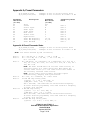
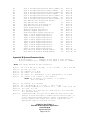
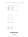
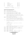
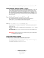
Note 23:
Note 24:
Note 25:
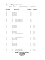
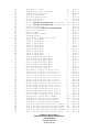
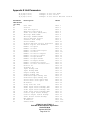
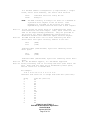
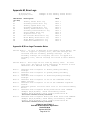
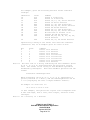
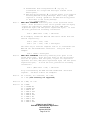
Number of Zones and Detectors
Current Serial (RS-232 and Ethernet) Receive/Transmit ID,
shadows System setting
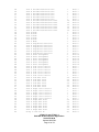
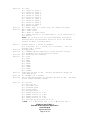
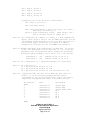
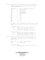
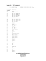
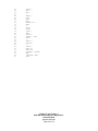
Bitmaps indicating which inputs are valid with the current
hardware configuration. If the bit is set (i.e. 1) that
particular input is valid.
LSB/MSB Word
LSB
LSB
LSB
LSB
LSB
LSB
LSB
LSB
MSB
MSB
MSB
MSB
Bit
0
1
2
3
4
5
6
7
0
1
2
3
Input Represented
FM
AM
Zone Dedicated IN
In 1
In 2
In 3
In 4
In 5
In 6
In 7
In 8
In 9
For example, a fully loaded CT600.3 (3 input boards, 2 output
boards, and 3 tuner modules) would have the following return
values:
20=FF
valid
21=F
Indicates FM, AM, Zone Dedicated IN, In 1-5
Indicates In 6-9 valid
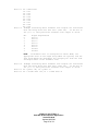
In a minimal CT600.0 configuration (2 input boards, 1 output
board, and no tuner modules), the return value would be
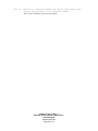
Note 26:
20=FC
Indicates Zone Dedicated Input and In 1-5
valid, No FM, AM
21=01
Indicates In 6 valid, No In 7-9
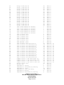
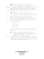
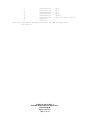
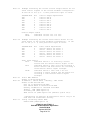
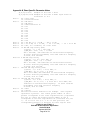
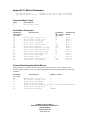
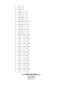
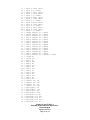
Bitmaps indicating which outputs are valid with the current
hardware configuration. If the bit is set (i.e. 1) that
particular output is valid.
LSB/MSB Word
LSB
LSB
LSB
LSB
LSB
LSB
LSB
LSB
Bit
0
1
2
3
4
5
6
7
Output Represented
Zone A
Zone B
Zone C
Zone D
Zone E
Zone F
unused
unused
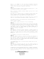
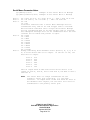
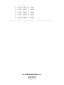
For example, a fully loaded CT600.3 (3 input boards, 2 output
boards, and 3 tuner modules) would have the following return
values:
22=3F
23=0
Indicates Zones A-F valid
Always 0
CT600.1-3 and CT300.1-3
BKC-DIP Product Specific Appendices
Version 2.00.06
Updated 08/27/09
Page 26 of 59