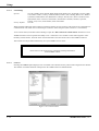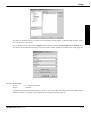
1
ADPRO ® FastTrace TM Installation & User Manual for 5, 10 and 20 Channel Models Part No. 201172.05 Introduction ADPRO FastTrace is an advanced, high performance digital video and audio recorder optimised for remote search and playback. Available in a number of models with either 5, 10 or 20 video inputs, ADPRO FastTrace provides outstanding transmission speed and picture quality for remote security and surveillance applications where secure, event-driven recording from multiple cameras onto digital data storage disks is required. In addition, ADPRO FastTrace can provide multi-user network access or dedicated telephone line connection for searching, retrieval and transmission of stored data from a remote monitoring site. Figure A shows a typical application using the ADPRO FastTrace system supporting the following equipment: • 5 camera (Model 5005), 10 camera (Model 5010) or 20 camera models (Model 5020) • 20 (or 30) external Alarm input devices (e.g. panic button, door switch, PIR (passive infra-red) detector or glass break switch) • 10 (or 20) external output devices (e.g. siren, strobe light, outdoor light or door lock mechanism) • 10 (or 20) Microphones and speakers (via the VM22A Audio Switcher) Figure A - Typical Application ADPRO FastTrace, Issue 5 iii Copyright & Tradename Statement Introduction Copyright The ADPRO FastTrace hardware, firmware and accompanying written materials are subject to copyright. Unauthorised copying of the firmware or the written materials is expressly forbidden. You may be held legally responsible for any copyright infringement. Tradename statement ADPRO is a registered trademark of Vision Systems Limited. ADPRO FastTrace is a trademark of Vision Fire & Security. The use of the words ‘ADPRO FastTrace’ in this manual should always be read to mean: ‘ADPRO FastTrace Multi-Site Video Security System’. ADPRO FastTrace, Issue 5 v Liability Introduction Summary of Limitation of Liability for Vision Fire & Security. This ADPRO Product must only be installed, configured and used strictly in accordance with the General Terms and Conditions and the Installation and Setup Manual available from Vision Fire & Security Pty Ltd. You acknowledge that you have read and agree to those terms and conditions. You acknowledge that you have been provided with a reasonable opportunity to appraise the ADPRO Product and have made your own independent assessment of the fitness or suitability of the ADPRO Product for your purpose. You acknowledge that you have not relied on any oral or written information, representation or advice given by or on behalf of Vision Fire & Security or its representatives. Vision Fire & Security has no liability to you or any person for incidental or consequential loss, expense or damages including, without limitation, loss of business, loss of profits or loss of data. You indemnify Vision Fire & Security for any claim, amount or liability brought against Vision Fire & Security in connection with the ADPRO Product. You expressly agree that you assume the entire risk as to the results and performance of the ADPRO Product resulting from the configuration of the ADPRO Product. Vision Fire & Security does not warrant, guarantee or make any representations, either expressly or implied, regarding the current or future use, or the results of the use, of the ADPRO Product, with respect to its correctness, accuracy, reliability, completeness, interworking, functionality, currentness or otherwise resulting from the configuration of the ADPRO Product. To the full extent permitted by law, Vision Fire & Security expressly excludes all conditions, warranties and liability, whether imposed or implied by statute or by rule of law or otherwise, which are not expressly set out in the General Terms and Conditions. To the extent permitted by law, your sole recourse for any defect of, damage to, or performance standard of the ADPRO Product will be under the express warranties the General Terms and Conditions (if applicable) and Vision Fire & Security will in no event be liable to pay any amount or damages resulting from or in connection with the ADPRO Product. To the extent by law that any limitation or exclusion can not apply, the total liability of Vision Fire & Security in relation to the ADPRO Product is limited to: (a) (b) in the case of services, the cost of having the services supplied again; or in the case of goods, the lowest cost of replacing the goods, acquiring equivalent goods or having the goods repaired. To the extent permitted by law, Vision Fire & Security has no liability with respect to damage to or arising out of, or the condition or performance of, the ADPRO Product resulting from negligence or improper use, storage, installation, configuration or handling of the ADPRO Product (where ‘improper’ includes treatment other than in accordance with the ADPRO Manual, these terms and conditions or the in formation provided at a training session); or accident, unforeseeable circumstances or disaster; or modifications to the ADPRO Product other than in accordance with Vision Fire & Security' instructions; or attachment of or interoperation with features, software or products not approved by Vision Fire & Security in writing; or where the ADPRO Product has been serviced by persons not authorized by Vision Fire & Security in writing to service the ADPRO Product. Lightning or Related Voltage Surges ADPRO equipment malfunction caused by lightning or related voltage surges is specifically exempted from the warranty conditions of Vision Fire & Security Pty Ltd. Vision Fire & Security Pty Ltd reserves the right as to final determination of whether or not an equipment malfunction was caused by lightning or related voltage surges. ADPRO FastTrace, Issue 5 vii Warranty Introduction You acknowledge that this is a summary of warranties and you have read and agree to the General Terms and Conditions. Capitalised terms below are defined in the General Terms and Conditions. Vision Fire & Security warrants that the ADPRO® Product will conform to its Specifications and perform its designed function during the Warranty Period. Vision Fire & Security also warrants that any component part of the ADPRO Product serviced or repaired by its authorised service department will remain in good working order for a period of 24 (twenty-four) months from the date of service. This warranty is only available on component parts of the ADPRO Product while the ADPRO Product is less than 7 (seven) years old commencing on the start of the Warranty Period and only covers those component parts of ADPRO Product serviced, repaired or replaced. If you notify Vision Fire & Security that the ADPRO Product, or component part of the ADPRO Product, under the warranty provided in clause 1.1 or 1.2 of these Conditions of use for the ADPRO Product, do not meet the Specification or perform its designed function respectively, Vision Fire & Security will, at its option, either repair or replace the ADPRO Product or its component parts at no additional charge. Component parts and replacement ADPRO Products will be furnished on an exchange basis and will, at the option of Vision Fire & Security either be new, equivalent to new or reconditioned. All replaced component parts and ADPRO Products become the property of Vision Fire & Security. Vision Fire & Security does not warrant, guarantee or make any representations, either expressly or implied, regarding the current or future use, or the results of the use, of the ADPRO Product, with respect to its correctness, accuracy, reliability, completeness, interworking, functionality, currentness or otherwise resulting from the configuration of the ADPRO Product. You acknowledge that no oral or written information, representation or advice given by or on behalf of Vision Fire & Security or its representatives, other than as contained in the General Terms and Conditions, creates a warranty or in any way increases the scope of these General Terms and Conditions, and you agree that you have not relied on any such information, representation or advice. The warranties contained in the General Terms and Conditions do not cover and, to the extent permitted by law, Vision Fire & Security has no liability with respect to damage to or arising out of, or the condition or performance of, the ADPRO Product resulting from negligence or improper use, storage, installation, configuration or handling of the ADPRO Product (where 'improper' includes treatment other than in accordance with the ADPRO Manual, these terms and conditions or the in formation provided at a training session); or accident, unforeseeable circumstances or disaster; or modifications to the ADPRO Product other than in accordance with Vision Fire & Security' instructions; or attachment of or interoperation with features, software or products not approved by Vision Fire & Security in writing; or where the ADPRO Product has been serviced by persons not authorized by Vision Fire & Security in writing to service the ADPRO Product. ADPRO FastTrace, Issue 5 ix Introduction DECLARATION OF CONFORMITY Manufacturer's Name: Manufacturer's Address: Vision Fire & Security Pty Ltd. 14 Park Way Technology Park Mawson Lakes SA 5095 Australia. declares, that the product(s): Product Name: Model Number: ADPRO FastTrace Multi-Site Video Security System AFT-5005-X-Y AFT-5020-X-Y AFT-5010-X-Y X = Number of Hard Disk Drives between 1 - 4. Y = Number of Video Compression Engines between 1 - 4. Product Options: All meet the Standards detailed below. Declaration of Conformity EMC Emissions EN55022:1998 (CISPR 22:1997) / AS/NZS 3548:1995 + A1, A2 Class A Conducted and radiated emissions. FCC Part 15 Class A Conducted and radiated emissions. EN 61000-3-2:1995 Current harmonic emissions. EN 61000-3-3:1995 Voltage fluctuations and flicker. EMC Immunity EN 50130-4:1995 +A1 Alarm systems immunity. Safety EN 60950:1992 +A1, A2, A3, A4, + A11 IEC 60950:1991 +A1, A2, A3, + A4 Supplementary Information The products listed comply with the requirements of the Low Voltage Directive 73/23/EEC (where applicable) and the EMC Directive 89/336/EEC and carries the CE marking accordingly. The products were tested in a typical configuration. ADPRO FastTrace, Issue 5 xi Safety Procedures WARNING INFORMATION Installations in the United States of America and Canada For systems installed in the United States of America and Canada the following requirement is applicable: All equipment installations are required to be in accordance with the National Electrical Code (NEC) ANSI/NFPA 70 and the Canadian Electrical Code (CEC) Part 1, CAN/CSA C22.1. If the power cord is not supplied with the ADPRO FastTrace, select the proper power cord according to your local national electricity code. USA: use a UL listed type SVT or SJT detachable power cord. Canada: use a CSA certified detachable power cord. Radio Interference The ADPRO FastTrace complies with Part 15 of the FCC Rules. Operation is subject to the following two conditions: (1) This device may not cause harmful interference, and (2) this device must accept any interference received, including interference that may cause undesired operation. The ADPRO FastTrace complies with the electromagnetic emission limit requirements of AS/NZS 3548 and EN55022 Class A. In a domestic environment this product may cause radio interference in which case the user may be required to take adequate measures. Static Discharge ADPRO FastTrace system components contain electrical parts that are susceptible to damage from static discharge. Static voltages of one (1) to thirty (30) kilovolts are common in unprotected environments. When installing or servicing ADPRO FastTrace equipment, it is advisable to observe the following standard precautions for handling electronic assemblies to reduce the risk of component damage: • Minimise handling of electronic assemblies and components, • Transport, temporarily arrange and store electronic components in recognised anti-static containers, • Discharge any static voltage from your body before handling electronic components or wear a grounded, Safety-Standard Approved, anti-static wrist strap while handling components, and • Avoid handling electronic components in areas which have a floor or work-surface capable of generating a static charge. Internal Lithium Battery WARNINGS The ADPRO FastTrace contains an internal lithium battery. There is danger of explosion if the battery is incorrectly replaced. The battery is not user replaceable and can only be replaced by Vision Fire & Security or their Authorised Service Representative. ADPRO FastTrace, Issue 5 Safety Procedures WARNING Connection to Other Equipment All interface ports on the ADPRO FastTrace must be only connected to other equipment or systems that are Safety Extra Low Voltage (SELV) rated. Failure to do so will invalidate the electrical safety approval and may cause injury or loss of life. SAFETY WARNING The ADPRO FastTrace is a Class 1 electrical product and must always be connected to a grounded power outlet. Always ensure that ADPRO FastTrace is installed adjacent to a grounded power outlet. ADPRO FastTrace, Issue 5 Table of Contents 1 1.0 Installation ................................................................................................................................................................. 1-1 1.1 Unpacking the ADPRO FastTrace ......................................................................................................... 1-3 1.2 Physical Location ..................................................................................................................................... 1-3 1.3 General Power Requirements................................................................................................................. 1-4 1.3.1 Power Conditioners and Surge Arresters............................................................................. 1-4 1.3.2 Interference Caused by Ground Loops ................................................................................ 1-4 1.4 Familiarisation ......................................................................................................................................... 1-5 1.5 System Wiring Considerations ............................................................................................................... 1-7 1.5.1 Electromagnetic Compatibility (EMC) Issues and Instructions ........................................ 1-7 1.5.1.1 FCC Advice for Installers and Users in the United States .................................... 1-8 1.6 Mounting the ADPRO FastTrace........................................................................................................... 1-8 1.6.1 Rack Mounting........................................................................................................................ 1-8 1.7 Setting the Video Standard ..................................................................................................................... 1-9 1.8 Video Input Connections......................................................................................................................... 1-9 1.8.1 Video Input Requirements................................................................................................... 1-10 1.8.1.1 Maximum Camera Input Cable Length ............................................................... 1-10 1.9 Video Output (Monitor Output)........................................................................................................... 1-10 1.10 Connecting Communications Devices.................................................................................................. 1-10 1.10.1 COMMS 1.............................................................................................................................. 1-11 1.10.2 COMMS 2.............................................................................................................................. 1-11 1.10.3 NETWORK Port................................................................................................................... 1-12 1.10.4 Network Port Pinout............................................................................................................. 1-13 1.11 GP Serial Port (1 and 2) ........................................................................................................................ 1-13 1.12 PTZ Port ................................................................................................................................................. 1-14 1.12.1 PTZ Port Setup ..................................................................................................................... 1-15 1.13 Alarm Inputs .......................................................................................................................................... 1-16 1.13.1 Driving the Alarm Inputs..................................................................................................... 1-16 1.14 Control Outputs ..................................................................................................................................... 1-18 1.14.1 Connecting to the Control Outputs..................................................................................... 1-18 1.15 Mode Select Input .................................................................................................................................. 1-19 1.16 Access/Secure Input ............................................................................................................................... 1-19 1.17 General Alarm Relay Output ............................................................................................................... 1-20 1.18 Audio Connections................................................................................................................................. 1-20 1 2.0 Setup........................................................................................................................................................................... 2-1 2.1 Power Up .................................................................................................................................................. 2-3 2.2 Access to the User Settings Menu ........................................................................................................... 2-3 2.2.1 Local Setup .............................................................................................................................. 2-4 2.2.1.1 Installing ADPRO Video Central Lite .................................................................. 2-5 2.2.1.1.1 Configuring ADPRO Video Central Lite & ADPRO FastTrace........................... 2-5 2.2.1.1.2 Accessing ADPRO FastTrace for the first time .................................................... 2-6 2.2.1.1.3 Optional Network Connection Settings................................................................. 2-7 2.2.1.1.4 Connecting to the ADPRO FastTrace ................................................................... 2-8 2.2.1.1.5 Setting the Operational Parameters: ...................................................................... 2-9 2.2.1.1.6 Setting the ADPRO Video Central Lite Telephone (Dial-up) Connection ........... 2-9 2.2.1.1.7 Video Central Lite Settings for a Network Connection ........................................ 2-9 2.2.2 Leaving User Settings ........................................................................................................... 2-10 2.2.3 Remote Setup......................................................................................................................... 2-10 2.3 User Settings Menu ................................................................................................................................ 2-10 2.3.1 Site Details ............................................................................................................................. 2-11 2.3.1.1 Site Name ............................................................................................................ 2-12 2.3.1.2 Passwords ............................................................................................................ 2-12 2.3.1.3 Date/Time Settings .............................................................................................. 2-12 2.3.1.3.1 Time Zone ........................................................................................................... 2-13 ADPRO FastTrace, Issue 5 Table of Contents 2.3.2 2.3.3 2.3.1.3.2 Daylight Saving ................................................................................................... 2-13 Communications ................................................................................................................... 2-13 2.3.2.1 Ethernet Properties .............................................................................................. 2-14 2.3.2.1.1 IP Address for this Unit....................................................................................... 2-14 2.3.2.1.2 Subnet Mask ........................................................................................................ 2-14 2.3.2.1.3 Default Gateway .................................................................................................. 2-15 2.3.2.1.4 Video Data Rate .................................................................................................. 2-15 2.3.2.2 Serial Communication Properties........................................................................ 2-15 2.3.2.2.1 Modem/TA Model............................................................................................... 2-16 2.3.2.2.2 Line Type............................................................................................................. 2-17 2.3.2.2.3 Data Rate ............................................................................................................. 2-17 2.3.2.2.4 Dial Time............................................................................................................. 2-17 2.3.2.2.5 Answer Rings ...................................................................................................... 2-17 2.3.2.2.6 Initialisation String .............................................................................................. 2-18 2.3.2.2.7 Advanced Serial Communications Settings ........................................................ 2-18 2.3.2.2.8 Local IP Address ................................................................................................. 2-18 2.3.2.2.9 Enable PAP.......................................................................................................... 2-19 2.3.2.2.10 PPP Username ..................................................................................................... 2-19 2.3.2.2.11 PPP Password ...................................................................................................... 2-19 2.3.2.2.12 Nominal Data Rate (bits/sec)............................................................................... 2-19 2.3.2.3 Advanced Communication Properties................................................................. 2-20 2.3.2.3.1 Call List ............................................................................................................... 2-20 2.3.2.3.2 Main Communications Link................................................................................ 2-21 2.3.2.3.3 Connection Attempts ........................................................................................... 2-21 2.3.2.3.4 Connection Separation (seconds) ........................................................................ 2-22 2.3.2.4 Backup Communications..................................................................................... 2-22 Connected Equipment .......................................................................................................... 2-23 2.3.3.1 General Alarm Relay Settings ............................................................................. 2-23 2.3.3.1.1 Active When ........................................................................................................ 2-23 2.3.3.2 PTZ Settings ........................................................................................................ 2-24 2.3.3.3 Cameras ............................................................................................................... 2-24 2.3.3.3.1 Camera Name ...................................................................................................... 2-25 2.3.3.3.2 Colour/Monochrome Camera .............................................................................. 2-25 2.3.3.3.3 Camera Terminated ............................................................................................. 2-25 2.3.3.3.4 This Camera has a PTZ Station ........................................................................... 2-25 2.3.3.3.5 Use Activity Detection ........................................................................................ 2-26 2.3.3.3.6 Sensitivity ............................................................................................................ 2-26 2.3.3.3.7 Hold Time............................................................................................................ 2-26 2.3.3.3.8 Activity Detection Area....................................................................................... 2-26 2.3.3.3.9 Contrast Monitoring ............................................................................................ 2-27 2.3.3.4 Monitor ................................................................................................................ 2-28 2.3.3.4.1 Sequence List....................................................................................................... 2-28 2.3.3.4.2 Dwell Time.......................................................................................................... 2-28 2.3.3.5 Transaction Devices ............................................................................................ 2-28 2.3.3.5.1 Device Name ....................................................................................................... 2-29 2.3.3.5.2 Protocol................................................................................................................ 2-30 2.3.3.5.3 Communications Link ......................................................................................... 2-30 2.3.3.5.4 Connection Port ................................................................................................... 2-30 2.3.3.5.5 Configure Connection ......................................................................................... 2-30 2.3.3.5.5.1 ATM IP Address.................................................................................................. 2-30 2.3.3.5.5.2 Central IP Address............................................................................................... 2-31 2.3.3.5.5.3 Baud Rate for Serial Connection ......................................................................... 2-31 2.3.3.5.5.4 Parity.................................................................................................................... 2-31 2.3.3.5.5.5 Data Bits .............................................................................................................. 2-31 2.3.3.5.5.6 Stop Bits .............................................................................................................. 2-31 2.3.3.5.5.7 Flow Control........................................................................................................ 2-32 ADPRO FastTrace, Issue 5 Table of Contents 2.3.4 ADPRO FastTrace, Issue 5 2.3.3.5.5.8 Configure Transaction Data ................................................................................ 2-32 2.3.3.5.6 Transparent Data Port.......................................................................................... 2-32 2.3.3.5.6.1 Baud Rate ............................................................................................................ 2-33 2.3.3.5.6.2 Parity.................................................................................................................... 2-34 2.3.3.5.6.3 Data Bits .............................................................................................................. 2-34 2.3.3.5.6.4 Stop Bits .............................................................................................................. 2-34 2.3.3.5.6.5 Flow Control........................................................................................................ 2-34 2.3.3.5.7 Alarm Inputs........................................................................................................ 2-34 2.3.3.5.7.1 Alarm Input Name ............................................................................................... 2-35 2.3.3.5.7.2 Alarm Type.......................................................................................................... 2-35 2.3.3.5.7.3 Hold Time............................................................................................................ 2-36 2.3.3.5.7.4 Camera View Style for the Triggered Alarm ...................................................... 2-36 2.3.3.5.8 Control Outputs ................................................................................................... 2-36 2.3.3.5.8.1 Control Output Name .......................................................................................... 2-37 2.3.3.5.8.2 Default State ........................................................................................................ 2-37 2.3.3.5.8.3 Manual Operation................................................................................................ 2-37 2.3.3.5.8.4 Disconnect Operation .......................................................................................... 2-38 2.3.3.5.9 Audio ................................................................................................................... 2-38 2.3.3.5.9.1 Audio Input.......................................................................................................... 2-38 2.3.3.5.9.2 Microphone Gain Operation................................................................................ 2-38 2.3.3.5.9.3 Audio Input Gain ................................................................................................. 2-39 2.3.3.5.9.4 Audio Out Volume .............................................................................................. 2-39 Operational Behaviour ......................................................................................................... 2-39 2.3.4.1 Data Storage ........................................................................................................ 2-39 2.3.4.1.1 Normal (Recording Retention Time)................................................................... 2-39 2.3.4.1.2 Event (Recording Retention Time) ..................................................................... 2-40 2.3.4.2 Operational Modes .............................................................................................. 2-40 2.3.4.2.1 Operational Modes .............................................................................................. 2-40 2.3.4.2.1.1 Recording Mode Name........................................................................................ 2-40 2.3.4.2.2 Mode Selection .................................................................................................... 2-41 2.3.4.3 Audio Behaviour ................................................................................................. 2-41 2.3.4.4 Camera Behaviour ............................................................................................... 2-41 2.3.4.4.1 Video Capture (tab) ............................................................................................. 2-42 2.3.4.4.2 Recording Type ................................................................................................... 2-42 2.3.4.4.3 Capture Settings - Defaults.................................................................................. 2-43 2.3.4.4.4 Event Triggers ..................................................................................................... 2-44 2.3.4.4.4.1 Alarm Logic......................................................................................................... 2-44 2.3.4.4.4.2 Event Inputs......................................................................................................... 2-44 2.3.4.4.5 Event Response ................................................................................................... 2-44 2.3.4.4.5.1 Activate Control Output ...................................................................................... 2-44 2.3.4.4.5.2 Dial Out on Event................................................................................................ 2-45 2.3.4.4.5.3 Dial Out on Video Loss....................................................................................... 2-45 2.3.4.4.5.4 Dial Out on Invalid Contrast ............................................................................... 2-45 2.3.4.4.5.5 Record Audio on Event ....................................................................................... 2-45 2.3.4.5 Multi-Screen Live Behaviour .............................................................................. 2-46 2.3.4.5.1 Guard Tour Settings ............................................................................................ 2-47 2.3.4.5.2 Selectable Multi-Screen Settings......................................................................... 2-47 2.3.4.5.2.1 Adding a new profile ........................................................................................... 2-48 2.3.4.5.2.2 Renaming an existing profile............................................................................... 2-48 2.3.4.5.2.3 Copy and paste an existing profile ...................................................................... 2-48 2.3.4.5.2.4 Deleting an existing profile ................................................................................. 2-48 2.3.4.5.2.5 Adding a camera from the Cameras listbox to the Profile Layout control.......... 2-49 2.3.4.5.2.6 Modifying a Profile Layout ................................................................................. 2-50 2.3.4.6 Entry/Exit Behaviour........................................................................................... 2-50 2.3.4.6.1 Entry Path and Delay........................................................................................... 2-51 2.3.4.6.2 Entry Point and Entry Delay................................................................................ 2-51 Table of Contents 2.4 2.3.4.6.3 Entry Path Zone(s)............................................................................................... 2-51 2.3.4.6.4 Exit Path and Delay ............................................................................................. 2-52 2.3.5 Maintenance .......................................................................................................................... 2-52 2.3.5.1 Temperature Monitor........................................................................................... 2-53 Event Log................................................................................................................................................ 2-54 1 3.0 Specifications............................................................................................................................................................. 3-1 3.1 ADPRO FastTrace Version 1.02............................................................................................................. 3-3 3.2 ADPRO Video Central Lite Version 8.04.............................................................................................. 3-6 List of Figures Figure 1-1 - ADPRO FastTrace rear panel connectors ................................................................................................................ 1-5 Figure 1-2 - Configuration Switch Settings ................................................................................................................................. 1-7 Figure 1-3 - ADPRO FastTrace front panel for 19 inch rack mount models .............................................................................. 1-8 Figure 1-4 - Typical RS485 connection to multiple telemetry stations..................................................................................... 1-14 Figure 1-5 - PTZ port connections to the telemetry station ....................................................................................................... 1-15 Figure 1-6 - Pin Numbering of the PTZ port ............................................................................................................................. 1-15 Figure 1-7 - Alarm Connector Pinouts ...................................................................................................................................... 1-16 Figure 1-8 - Pinouts for Control Output Connectors ................................................................................................................. 1-18 Figure 1-9 - External Relay - Typical output circuit ................................................................................................................. 1-19 Figure 1-10 - Audio Connector Pinouts..................................................................................................................................... 1-21 Figure 2-1 - Local setup configuration ........................................................................................................................................ 2-4 Figure 2-2 - Null-modem cable wiring for local connection ....................................................................................................... 2-4 Figure 2-3 - User Settings menu .................................................................................................................................................. 2-8 Figure 2-4 - Site Details menu................................................................................................................................................... 2-11 Figure 2-5 - Communications menu .......................................................................................................................................... 2-13 Figure 2-6 - Serial Communication Port Settings Menu ........................................................................................................... 2-16 Figure 2-7 - Call List menu........................................................................................................................................................ 2-20 Figure 2-8 - Call List (Ethernet-left, Serial-right) Properties .................................................................................................... 2-21 Figure 2-9 - Connected Equipment menu.................................................................................................................................. 2-23 Figure 2-10 - Cameras Menu ..................................................................................................................................................... 2-24 Figure 2-11 - Alarm Contacts List ............................................................................................................................................. 2-35 Figure 2-12 - Control Output Settings Menu............................................................................................................................ 2-37 List of Tables Table 1-1 - COMMS1 25-pin D connector pins ........................................................................................................................ 1-11 Table 1-2 - 9-pin D connector pins............................................................................................................................................ 1-11 Table 1-3 - Network Port pin outs ............................................................................................................................................. 1-13 Table 1-4 - GP Serial port pin outs ............................................................................................................................................ 1-14 Table 1-5 - Audio Switcher signals -15-pin D connector .......................................................................................................... 1-20 Table 1-6 - Local Audio signals 9-pin DECA connector .......................................................................................................... 1-21 Table 2-1 - Quality Value versus Resolution............................................................................................................................. 2-43 ADPRO FastTrace, Issue 5 1.0 1 Installation Installation 1.1 Unpacking the ADPRO FastTrace After unpacking the ADPRO FastTrace, carefully check for any sign of damage. Any damage should be reported before installation to your supplier or to Vision Fire & Security directly. Check that the ADPRO FastTrace packing carton contains the following items: 1 1 1 1 1 4 or 6 1 ADPRO FastTrace chassis CD-ROM containing ADPRO Video Central Lite Software Installation and Setup Manual Null-modem cable 1m, (3ft) 9-way screw terminal plug 15-way screw terminal plug (Model 5005=4, Model 5010=4, Model 5020=6) IEC power cord NOTE The ADPRO FastTrace Installation and Setup Manual is also available in PDF format on the CD-ROM. 1.2 Physical Location The location within the protected premises of the ADPRO FastTrace should be considered carefully and the following notes are provided for guidance. • Physical Security - The ADPRO FastTrace should be located where it will remain secure under all conditions, even when the premises are open or occupied. The safest place would be a room (or cabinet) with a lockable door. It should not be visible from outside the premises and not be accessible to occupant or visitor tampering. WARNINGS ADPRO FastTrace equipment must be used only in an INDOOR environment. • System Wiring - Ideally, the ADPRO FastTrace’s position will be close to the centre of the site wiring. Excessive cable runs will increase the installation cost, cause voltage drops, degrade signals, and offer greater scope for EMI/RFI (electrical interference) induced faults, tampers, and false alarms. Wiring considerations should include the following: • The largest wiring requirement is the coaxial camera cabling and the wiring to the alarm input and output devices • Mains power • The system requires at least one video camera and associated coaxial cabling for system setup ADPRO FastTrace, Issue 5 1-3 Installation • 1.3 Environment - Choose an inside location that is cool and dry. Do not mount the ADPRO FastTrace anywhere near machinery that generates heat, toxic fumes and dust. Do not mount the ADPRO FastTrace in close proximity to sources of radio frequency or other electromagnetic radiation. These include radio transmitters (both fixed and portable), electric motors, refrigeration or air conditioning systems and high power or multiphase switching equipment. General Power Requirements Any AC supply connected to the ADPRO FastTrace should be: • Provided from a reliable electric supply company - typically this means that the power is not disconnected (or lost) for any more than eight (8) hours at a time in any thirty six (36) hour period and infrequently in a single year • Provided from a supply bus within the protected premises that is not isolated at night (or out of hours) or time switched. The supply should be free from voltage spikes or current surges (connected to high power switching equipment or electric motors) • Supplied directly to the ADPRO FastTrace via circuits that cannot be switched off, intentionally or accidentally Always consider local regulations, standards, and guidelines for mains power connected systems. 1.3.1 Power Conditioners and Surge Arresters The use of an Uninterruptable Power Supply (UPS) should be considered in situations where the mains power is unreliable. A good UPS has the ability to remove interference, sags, and power surges that can cause false alarms, equipment failure or even terminal damage. UPS’s are used effectively on all major computer installations and the microelectronics used in many video and alarm systems (including ADPRO FastTrace) are similar, both in their functionality, and their susceptibility to ‘dirty’ mains power. Power line conditioners or surge arresters can help prevent mains distortion of voltage, current, and frequency caused by load switching, large electric motors, and lightning. These distortions can cause unreliable operation, false alarms, and equipment failure, damage or even total destruction. 1.3.2 Interference Caused by Ground Loops In some installations, where cameras or monitors are located at a distance from the ADPRO FastTrace rack, considerable ground loop currents can be generated and may cause interference. Supplying power to different components of the ADPRO FastTrace system may also cause ground loop currents. For example, cameras, monitors and the ADPRO FastTrace chassis may receive power from different phases of a multiphase supply. Wherever possible, source power to all components of the system from a common phase of the supply. Where ground loop currents cause a problem in an ADPRO FastTrace installation, the installer may reduce the effect by installing a video isolation transformer on each video channel affected. 1-4 ADPRO FastTrace, Issue 5 Installation 1.4 Familiarisation All external connections to the ADPRO FastTrace chassis are made via the rear panel, refer to Figure 1-1: Model 5020 ALARM INPUTS CONTROL OUTPUTS AUDIO DATA PTZ GP SERIAL 2 GP SERIAL 1 AUDIO SWITCHER CAMERAS 1 3 2 11 ALARM INPUTS 5 4 13 12 7 6 15 14 16 8 18 17 9 19 10 20 MONITORS USB CONFIGURATION MON-1 NETWORK COMMS 1 COMMS 2 NETWORK COMMS 1 COMMS 2 Model 5010 ALARM INPUTS ALARM INPUTS CONTROL OUTPUTS AUDIO DATA PTZ GP SERIAL 2 GP SERIAL 1 AUDIO SWITCHER CAMERAS 1 3 2 5 4 6 7 8 9 10 MONITORS USB CONFIGURATION MON-1 Model 5005 ALARM INPUTS ALARM INPUTS CONTROL OUTPUTS AUDIO DATA PTZ GP SERIAL 2 GP SERIAL 1 AUDIO SWITCHER CAMERAS 1 2 MONITORS MON-1 3 4 5 CONFIGURATION USB NETWORK COMMS 1 COMMS 2 Figure 1-1 - ADPRO FastTrace rear panel connectors The connectors on the rear panel are arranged into a number of logical groups: VIDEO • • CAMERAS - (BNC-Female) - input channels for cameras or composite video MON 1- (BNC - Female) - output for composite video monitor CONFIGURATION - (Dipswitch) - used to configure ADPRO FastTrace operation and electrical interfaces. COMMUNICATIONS • • • • USB - (2 USB ports) - (not available in current version) NETWORK - (RJ-45 - Female) - Ethernet 10/100baseT COMMS 1 - (25-pin D - Male) - V.28 interface for a maximum 230Kbps data rate COMMS 2 - (9-pin D - Male) - V.28 interface for a maximum 230Kbps data rate ADPRO FastTrace, Issue 5 1-5 Installation INPUT-OUTPUT • GP SERIAL 1 - (9-pin D - Male) - RS-232 serial port with maximum 38,400 bps data rate • GP SERIAL 2 - (9-pin D - Male) - RS-232 serial port with maximum 38,400 bps data rate • PTZ - (9-pin D - Male) - RS485, for connection to camera stations. Protocol is dependent on the camera station type and model • DATA - (9-pin D - Male) - RS-232 data port with a maximum 57,600 bps. • IN/OUT - (15-pin screw) • EE - Export Evidence (not used in current version) • A/S - Access / Secure input to control the remote dialling capability • CLK - (not used in current version) • SPARE - Spare • MOD SEL - Mode Select input to switch operational mode via hardware • FLT - Fault Relay output - COM, N/O and N/C contacts • ALM - General Alarm Relay output - COM, N/O and N/C contacts AUDIO The AUDIO connector - (9-pin screw) is used to connect to local audio equipment. • • • • OUT - Line Output with 600Ω impedence IN - Line Input with 6KΩ impedence SPKR +/- - Local connection for 8Ω speaker MIC +/- - Local connection for 600Ω microphone AUDIO SWITCHER connector - (15-pin D - Male) - Channel select outputs for control of the ADPRO VM22A Audio Switcher unit. ALARM and CONTROL The ALARM INPUT - (15-pin screw) connectors supports direct alarm device connections. • Up to thirty (30) external Alarm Inputs can be connected (20 only on Model 5010 and Model 5005). Inputs can be programmed (via a setup menu) to trigger an alarm on either open or closed contacts The CONTROL OUTPUT - (15-pin screw) connectors supports direct alarm device connections: • Twenty (20) Control Outputs (10 only on Model 5010 and Model 5005) low power open drain transistor outputs. For high power/voltage equipment, suitable interface circuitry must be used POWER IEC 3-pin connector for use with 115 V - 230 V AC, 47 - 63 Hz input power. Maximum input current is 5 amps. Typical unit power consumption when fully optioned is 100 W. 1-6 ADPRO FastTrace, Issue 5 Installation CONFIGURATION SWITCH ON 1 2 3 4 5 6 7 8 9 10 11 12 * * * * * * NOTE - Factory setting - DO NOT change (12-11) Factory Set ON, ON (10) VIDEO STANDARD ON = RS170 (NTSC) OFF = CCIR (PAL) (9) GP Serial 2 ON = ATM OFF = Debug (8) PTZ PORT TERMINATION ON = RS485 with 120 ohm termination OFF = RS485 without termination (7) COMMS 2 PORT OPERATION ON = DIRECT CONNECT OFF = NORMAL (6) Factory Set OFF (5) PTZ PORT ELECTRICAL INTERFACE ON = RS422 OFF = RS485 (4) Factory Set OFF (1-3) Factory Set OFF, ON, OFF P73 config switch.cdr Figure 1-2 - Configuration Switch Settings 1.5 System Wiring Considerations 1.5.1 Electromagnetic Compatibility (EMC) Issues and Instructions When an ADPRO FastTrace system is installed in accordance with the recommendations and procedures in this manual, it will meet the EMC requirements of: • EN 55022 / AS3548 Class A, and FCC Part 15 Class A digital devices in respect to emissions, and • EN 50130-4 Alarm Systems Immunity. To ensure EMC compliance for your system installation, make sure of the following: • CAT-5 Unshielded Twisted Pair (UTP) Data Cable is used for the Network port connection, • RG-59 coaxial 75ohm Video cable is used for all composite video connections and the cables are terminated with 75 ohm BNC connectors, and • Where possible, all cables should be shielded (single or dual) twisted pair and the shield itself, along with the associated drain wire, terminated at the ADPRO FastTrace with a connection to the chassis. Note that the foil used in some shielded cable is only insulated on one side. Always check the foil shield with an ohmmeter and make sure that the conductive side is in contact with shield termination recommendations in this manual. ADPRO FastTrace, Issue 5 1-7 Installation 1.5.1.1 FCC Advice for Installers and Users in the United States ADPRO FastTrace equipment has been tested and found to comply with the limits for a Class A digital device, pursuant to part 15 of the FCC Rules. These limits are designed to provide reasonable protection against harmful interference in a residential installation. This equipment generates, uses and can radiate radio frequency energy and, if not installed and used in accordance with the instructions, may cause harmful interference to radio communications. However, there is no guarantee that interference will not occur in a particular installation. If this equipment does cause harmful interference to radio or television reception, which can be determined by turning the equipment off and on, the user is encouraged to try to correct the interference by one or more of the following measures: • Reorient or relocate the receiving antenna • Increase the separation between the equipment and receiver • Connect the equipment into an outlet on a circuit different from that to which the receiver is connected • Consult the dealer (or installer) or an experienced radio/TV technician for help WARNINGS Changes or modifications not expressly approved by Vision Systems could void the user's authority to operate this equipment. 1.6 Mounting the ADPRO FastTrace 1.6.1 Rack Mounting The ADPRO FastTrace models are housed in a 3 U high chassis for mounting in a 19" rack with a layout as shown in Figure 1-3. To ensure long term electronic equipment reliability, it is advisable to: • mount the unit clear of other equipment which can dissipate large amounts of heat, • ensure adequate air flow (either convective or forced) between the unit and its surroundings, and • ensure that the fan opening on the rear panel is not blocked by other equipment. Figure 1-3 - ADPRO FastTrace front panel for 19 inch rack mount models 1-8 ADPRO FastTrace, Issue 5 Installation 1.7 Setting the Video Standard ADPRO FastTrace can be set to operate using either PAL (CCIR) or NTSC (RS170) video standards. Once a standard has been selected, all video inputs and the Monitor output (Composite video) will be configured to use the same standard. To set the required video standard, use the Configuration DIP switch on the rear panel. Configuration Switch # 10 ON = NTSC OFF = PAL NOTE To be configured correctly, this switch must be set before power on. 1.8 Video Input Connections Depending on the model, up to 20 video sources can be connected via the female BNC sockets. The sources should generate a 1.0-volt peak to peak composite colour or black & white video signal when terminated with a 75-ohm load. A combination of colour and black & white cameras can be used. No external camera or system synchronisation is required. To ensure high picture quality, each video input must be terminated either at the chassis itself or by other external equipment. The Terminated option in the Camera Details menu allows individual channels to be terminated with 75ohm or left un-terminated, for example, when the video signal is looped out to other equipment such as a video monitor or video matrix switcher. The external equipment must provide the channel termination. The default menu option is Terminated. WARNING Video terminations are OFF when power is removed. The video terminators on the ADPRO FastTrace will disconnect when power to the unit is removed. If the video inputs are also connected to other equipment, the ADPRO FastTrace should NOT be used to provide a 75-ohm termination point. WARNING Installations in Lightning Prone Areas In lightning prone areas, in-line coaxial lightning arresters should be used on the video cables. The arresters should be installed at the cable entry of the building that houses the ADPRO FastTrace. Cameras should also have suitable lightning protection rods installed as close to them as possible. The use of fibre optics to provide electrical isolation on the video signals is strongly recommended in high-risk areas. ADPRO FastTrace, Issue 5 1-9 Installation 1.8.1 Video Input Requirements To ensure high quality images, the ADPRO FastTrace must synchronise correctly to the incoming video signal for the selected video standard. For synchronisation to occur the following conditions must be met: • the synchronisation pulse amplitude at each video input must be within the range of 0.2 volts to 0.4 volts, • the peak video amplitude with reference to the black level (ie. not including the synchronisation pulses) at each Video Input must be within the range of 0.5 volt to 1.0 volt, and • for colour cameras, the minimum colour burst level at each video input must be at least 100 mV. If the video level is low, cable compensators or video line drivers should be installed at the video source. They should be adjusted to boost the video signal to within the voltage limits given above. 1.8.1.1 Maximum Camera Input Cable Length The maximum cable length that can be used from a camera before cable compensators are required is dictated by the desired quality of the video picture. Generally, the shorter the cable between the camera and the ADPRO FastTrace the better the video picture quality. Use the following information as a guide for RG59 type coaxial cable (75 ohm nominal impedence): 1.9 • In a monochrome system, depending on the resolution required, the cable length should be restricted to 500 metres (1600 feet) before cable compensators are installed • Signal degradation due to the coaxial cables characteristics has a far greater effect on colour video. In a colour system, the coaxial cable length should be limited to 250 metres (800 feet) before cable compensators are installed. Again the length is dependent on the required picture quality Video Output (Monitor Output) Monitors can be colour or black and white, capable of receiving composite video signals via a 75 ohm BNC connector on the rear panel. Monitors must match the desired TV standard set for the chassis, either PAL (CCIR) or NTSC (RS 170). Use a monitor connected to the MON 1 video output to view the camera sequence in current use. 1.10 Connecting Communications Devices ADPRO FastTrace provides a number of interfaces for connecting communications devices to allow remote access to the system. These interfaces are available via the COMMS 1, COMMS 2 and NETWORK connectors on the rear panel. In general, there are three primary types of communication links available; dial-up, dedicated or network. Both dialup and dedicated links can be either analogue (PSTN) or digital (ISDN), depending of the type of connections available at the site. 1 - 10 ADPRO FastTrace, Issue 5 Installation 1.10.1 COMMS 1 COMMS 1 is a serial communications port and is used to connect to modems and terminal adaptors to support PSTN and ISDN links at data rates up to 230Kbps. The 25-pin D connector pins are wired as shown in the Table 1-1 below: PIN SIGNAL DESCRIPTION PIN 1 SGND Shield 14 2 TXD_A Transmit Data 15 3 RXD_A Receive Data 16 4 RTS_A Request to Send 17 SIGNAL SCT_A DCE Transmit Clock RXC_A DCE Receive Clock Data Terminal Ready 5 CTS_A Clear to Send 18 6 DSR_A Data Set Ready 19 7 GND Signal Ground 20 DTR_A 8 DCD_A Carrier Detect 21 RL_A RI 9 22 10 23 11 24 12 25 DESCRIPTION TXC_A Remote Loopback RI function DTE Transmit Clock 13 Table 1-1 - COMMS1 25-pin D connector pins 1.10.2 COMMS 2 COMMS 2 is used to connect to modems and terminal adaptors to support PSTN and ISDN links at data rates up to 230Kbps. It can also be used to access the ADPRO FastTrace setup menu and to upgrade the software when connected to a PC or laptop computer via a null-modem cable link. The 9-pin D connector pins are shown. PIN 1 2 3 4 5 6 7 8 9 SIGNAL DCD RXD TXD DTR GND DSR RTS CTS RI DESCRIPTION Carrier Detect Receive Data Transmit Data Data Terminal Ready Ground Data Set Ready Request to send Clear to send Ring Indicator Table 1-2 - 9-pin D connector pins ADPRO FastTrace, Issue 5 1 - 11 Installation 1.10.3 NETWORK Port Connection to an IEEE 802.3 Ethernet Local Area Network is via the NETWORK port. ADPRO FastTrace supports connection to 10baseT and 100baseT wiring systems. IMPORTANT NOTE To ensure correct network connectivity, please ensure ADPRO FastTrace is connected to the network before being powered on. This enables the ADPRO FastTrace unit to detect the correct network speed (10BaseT or 100BaseT). A network address is required for correct operation over a network. Both the ADPRO FastTrace and the PC running the ADPRO FastTrace PC software must have a unique TCP/IP address (referred to as the IP address). A number of IP parameters may need to be entered to correctly identify an ADPRO FastTrace on a network. IP Address The IP Address is used to identify each piece of equipment connected to the network. Each ADPRO FastTrace requires a unique IP address. The assigned IP Address is defined in 4 fields, for example: 123.07.231.72. Each field may contain an address element up to the value of 255. Subnet Mask Network devices communicate by using the subnet mask to determine whether the destination device is located on a local or a remote network. The assigned Subnet Mask is defined in 4 fields, for example: 255.255.0.0. Each field may contain a mask element up to the value of 255. Default Gateway For communication with a PC located on another network, the local ADPRO FastTrace must be given the address of the route to the other network. The default gateway is the address to which the local ADPRO FastTrace sends packets that are destined for the other network. NOTE Before configuring an ADPRO FastTrace for operation it is important that the IT or Network Manager assigns an IP Address for use by the device. This address is required for correct network operation. Addresses for the ‘subnet mask’ and the ‘gateway’ may also be required prior to commencement of the installation procedure. WARNINGS Remote setting of IP address Changing the IP address may mean you can no longer connect to the ADPRO FastTrace. 1 - 12 ADPRO FastTrace, Issue 5 Installation NOTE It is important that a gateway address is only entered if a gateway is present. Configuring the ADPRO FastTrace via the Ethernet connection is further discussed in the Setup Section (refer to Section 2.0). ADPRO WEBSITE For information regarding IP addressing when connecting through a network firewall, please refer to the Tech Tips page under the literature section on the ADPRO website at: http://www.adpro.com.au or contact your nearest ADPRO distributor for a copy. 1.10.4 Network Port Pinout The 8-pin RJ-45 Network port connector pinouts are shown below. Use Category 3, 4 or 5 cable when connecting to a 10baseT wiring system or network hub. Cat 5 cable must be used for operation on a 100baseT wiring system. RJ-45 PIN SIGNAL 1 2 3 4 5 6 7 8 Tx+ TxRx+ n/c n/c Rxn/c n/c Table 1-3 - Network Port pin outs 1.11 GP Serial Port (1 and 2) The General Purpose Serial Ports are used to connect the ADPRO FastTrace to other devices that use RS-232 signalling, for example Transaction Devices such as an ATM/POS terminal. If using the GP Serial Port for ATM/POS, please ensure that confuguration switch 9 is in the correct position prior to boot-up. Refer to Figure 1-2 for details. ADPRO FastTrace, Issue 5 1 - 13 Installation The pinouts for the 9-pin D male connectors are shown. PIN 1 2 3 4 5 6 7 8 9 SIGNAL DCD RXD TXD DTR GND DSR RTS CTS RI DESCRIPTION Carrier Detect Receive Data Transmit Data Data Terminal Ready Ground Data Set Ready Request to send Clear to send Ring Indicator Table 1-4 - GP Serial port pin outs 1.12 PTZ Port Telemetry stations are used for the control of cameras with Pan/Tilt/Zoom (PTZ) hardware. They are connected to the ADPRO FastTrace and can be controlled by commands issued via the PTZ port connector. ADPRO FastTrace supports a number of PTZ telemetry station models provided all of the PTZ units are the same model. Communications with the telemetry stations utilises RS485 ‘multi-drop’ signalling via the ‘PTZ’ port on the rear of the chassis. Figure 1-4 - Typical RS485 connection to multiple telemetry stations FastTrace V1.02 and above supports ‘Down the Coax’ telemetry. A ‘Down the Coax’ module is required to be installed in the FastTrace if this functionality is required. Please contact your ADPRO service centre if this option is required. 1 - 14 ADPRO FastTrace, Issue 5 Installation 1.12.1 PTZ Port Setup The following points are applicable to the PTZ port. • Telemetry stations are connected via a 9-pin D connector, marked ‘PTZ’ • RS485 control links allow cable lengths of up to 1000 metres • Up to 20 (identical) telemetry stations can be connected to one ADPRO FastTrace Use the following guidelines when connecting and setting up a telemetry station. • The same brand and model of telemetry station must be used at a site if multiple units are to be used • Set the address of the telemetry station to match the camera input to which the PTZ camera is connected • Use shielded twisted pair cable for connection to the telemetry stations • Connect the Transmit positive (TXD+ pin#2), Transmit negative (TXD- pin#3) and Ground terminal (pin#5) of the ADPRO FastTrace PTZ connector to the respective positive, negative and ground terminals of the telemetry station as shown in Figure 1-5 . Figure 1-5 - PTZ port connections to the telemetry station • Make sure the last telemetry station connected to the link is terminated in by a 120 ohm register • With reference to the telemetry station manual: i. ii. iii. connect the pan/tilt head and the zoom lens, focus control and iris control (if applicable), set the lens voltage, high speed PTZ settings, A/D converter for preset systems, homing preset after the last operation plus any other settings in the telemetry station, and make sure the telemetry station data speed is set to the recommended or default baud rate. Figure 1-6 - Pin Numbering of the PTZ port Telemetry station manufacturers provide a variety of models and features. ADPRO FastTrace provides PTZ control ability for a number of popular models and where possible, supports the features provided by the manufacturer. Due to the number of models available on the commercial market, details of connection and use for individual models have been provided on the ADPRO web site. ADPRO FastTrace, Issue 5 1 - 15 Installation . ADPRO WEBSITE For information regarding connection and features of specific telemetry station, please refer to the literature section on the ADPRO website at: http://www.adpro.com.au or contact yours nearest ADPRO distributor for a copy. 1.13 Alarm Inputs The ADPRO FastTrace Model 5020 has thirty external Alarm Inputs, all with selectable tamper detection configurations (Model 5005 and Model 5010 have twenty). The camera setup options can be programmed to trigger an alarm on detection of either a closed contact or an open contact condition on an Alarm Input. Alarm Inputs are normally connected to alarm sensors such as door switches, passive infrared detectors, microwave detectors, vibration sensors, electric field detectors, etc. 1.13.1 Driving the Alarm Inputs For an alarm input to be recognised, the input device must hold a changed state for a period of time. • For a valid closed contact, the total resistance, including wiring resistance, must be below 150 ohms • For an open contact to be valid the resistance presented at the Alarm Input must above 2,500 ohms The Alarm Inputs and numbering for all channels is shown in Figure 1-7. Note that the Alarm Input ground connections are not isolated from the chassis ground. Figure 1-7 - Alarm Connector Pinouts Wire connections from the alarm switches are made by using the screw terminal contact strips supplied with the ADPRO FastTrace. For ease of installation, the screw terminal blocks slide over the connector pins when the wiring is complete. 1 - 16 ADPRO FastTrace, Issue 5 Installation WARNING DO NOT attempt to solder directly onto the connector pins, as this may cause heat damage to the connector housing or to the interface PCB. The setup options for Alarm Inputs are described with reference to the ‘rest’ or non-alarm position of a set of switch contacts: • Normally Open - needs a closing alarm contact to activate an alarm • Normally Closed - needs an opening alarm contact to activate an alarm • SEOL Normally Open - Single End of Line termination with N/O contacts • SEOL Normally Closed - Single End of Line termination with N/C contacts • DEOL Normally Open - Dual End of Line termination with N/O contacts • DEOL Normally Open - Dual End of Line termination with N/C contacts ADPRO FastTrace, Issue 5 1 - 17 Installation 1.14 Control Outputs Control Outputs are used to control (switch on or off) external (third-party) equipment connected to the ADPRO FastTrace. NOTE Each Control Output can be set to be active (switch on) when an alarm event is active on the corresponding channel or to respond to remote control via Video Central. The Control Outputs can be used to initiate control of equipment such as lights, sirens, gates and control equipment. 1.14.1 Connecting to the Control Outputs Control Outputs are available via screw connection strips on the rear panel. Refer to Figure 1-8 for pin connections. Figure 1-8 - Pinouts for Control Output Connectors WARNING Exceeding the Control Output’s maximum voltage or current rating (12Vdc, 100mA) will damage the ADPRO FastTrace and invalidate the product warranty. For high power/voltage equipment, suitable interface circuitry must be used between the Control Outputs and the equipment. A typical output circuit for an external relay is shown in Figure 1-9. 1 - 18 ADPRO FastTrace, Issue 5 Installation Figure 1-9 - External Relay - Typical output circuit 1.15 Mode Select Input The way an ADPRO FastTrace operates its recording and alarm handling features can be changed by using up to four (4) different operating ‘modes’. The parameters that define a particular mode of operation, such as recording rate and alarm responses, are configured by using the FastTrace User Settings Menu. From the FastTrace User Settings Menu, any two (of the four) operating modes can be assigned to activate depending on the open/closed state of the Mode Select input pin. When the Mode Select pin is ‘open’ (or ‘high’), the ADPRO FastTrace operates by using the mode parameters assigned to that pin state. Placing a ‘closed contact’ on the pin switches the unit into an alternate mode. Please refer to Section 2.3.4.4.2 for more information on operating modes. 1.16 Access/Secure Input ADPRO FastTrace operation by default is in the Secure state and will respond to an Alarm Input by dialling/ connecting a remote user. The Access/Secure input allows the ADPRO FastTrace to be independently set into the Access state of operation. This input is usually connected to an alarm panel or access control system. In the Access state, trigger conditions on an Alarm Input may not cause a dial out depending on the programmed event response behaviour. For example, during business hours a remote site may be placed into the Access state when its local security system is deactivated, but will revert to the Secure state after hours. When the Access/Secure input pin is ‘open’ (or ‘high’), the ADPRO FastTrace operates in the Secure state. Placing a ‘closed contact’ on the pin (i.e. shorting to Ground) switches the unit into the Access state. NOTE An ADPRO FastTrace may be (remotely) placed into the Access or Secure state by the ADPRO Video Central User Interface. This action is independent of the signal level on the Access/Secure pin. After such a ADPRO Video Central over-ride, the access/secure input on the ADPRO FastTrace is ignored until the ADPRO Video Central disconnects. Subsequent changes of state in teh Access/Secure input will be recognised by the ADPRO FastTrace. ADPRO FastTrace, Issue 5 1 - 19 Installation 1.17 General Alarm Relay Output A Form C single pole changeover contact set is available on the rear panel. If configured to do so, the General Alarm relay activates while the ADPRO FastTrace has an alarm active. The contacts will remain in the changeover condition until all alarms are reset. Ratings: Switching Voltage Switching Current Isolation = = = 32VDC maximum 1Amp maximum 32V maximum The relay may also be configured to activate whenever the unit is connected via a network or data link to the Remote Viewing Software (e.g. ADPRO Video Central). This feature may be used (for instance) to notify a third-party alarm system when ADPRO FastTrace activity is taking place. 1.18 Audio Connections Audio functionality is provided via two connectors on the ADPRO FastTrace. The functions available are compatible with the ADPRO VM22A Audio Switchers. Audio Switcher Connector Pin Function Serial Link for Channel Number selection Audio Signals Spare Access/Secure Mode Select General Alarm Relay Ground VCC Signal Pin Specifications Serial Clock Serial Data Serial Strobe not used Audio Out (+) 14 7 15 8 1 Open drain output 32V maximum 100mA maximum On impedance <15 ohm Audio In (+) 2 Audio Common not used Acc/Sec Input M/Select Input Common N/O N/C Ground Power 9 13 5 6 4 12 11 10 3 Output impedance >6K ohm Nominal output level = 315mVrms Input impedance >6K ohm Nominal level = 10mVrms to 400mVrms Audio Signal common Contact Rating 1A at 32VDC 5VDC 3.5 watts max. Table 1-5 - Audio Switcher signals -15-pin D connector 1 - 20 ADPRO FastTrace, Issue 5 Installation Audio Connector Pin Function Line Level Audio Local Speaker Local Microphone Signal Pin Specifications Output 0 1 Common Input 2 3 Unbalanced, impedance 600 ohm Nominal voltage level = 315mVrms 0V Unbalanced, impedance >6K ohm Nominal level = 10mVrms to 400mVrms Ground Speaker (+) Speaker (-) 4 5 6 Ground Microphone (+) Microphone (-) 7 8 9 Balanced, impedance = 8 ohm Nominal output power = 1W Total harmonic distortion < 5% Differential impedance > 3K ohm Single ended impedance > 6K ohm Nominal signal level is 100uV rms to 10mV rms Table 1-6 - Local Audio signals 9-pin DECA connector Figure 1-10 - Audio Connector Pinouts ADPRO FastTrace, Issue 5 1 - 21 2.0 2 Setup Setup 2.1 Power Up The green Power and the red Status LED’s on the front panel are lit as soon as power is applied to the unit. The ADPRO FastTrace immediately starts to perform internal tests to ensure both software and hardware integrity. While the internal tests are executing, the Fault Relay is de-energised and the red Status LED is lit, or flashing. The Status LED will be ON during the initial stages of bootup then start flashing when the system is being initialized. This will allow the user to ascertain if the unit is in system initialization stage or if a fault is present that will prevent the system from correct operation. A successful self-test ensures all diagnostic tests have been passed and to confirm this, the red Status LED goes off and the Fault Relay is energised. NOTE The self-test function may take a few minutes to complete. During this period, any display on the local monitor screen is not meaningful and should be ignored. • If the self-test fails, the red Status LED remains ON • If the power fails, the green Power LED will be OFF If the diagnostic tests fail repeatedly, please contact your ADPRO supplier. 2.2 Access to the User Settings Menu User Settings menus are provided to quickly and easily configure the ADPRO FastTrace for operation. The menus and any associated stored parameters are held within non-volatile memory. There are two ways of accessing and viewing the User Settings Menus. 1) 2) Locally, by direct connection to a PC running ADPRO Video Central Lite software. Remotely, by using a communications link to connect on-line to a PC running the Video Central Lite software. NOTE After a local or remote connection has been established, to ensure that the latest version of the User Settings program is used, the Video Central Lite software will negotiate with the ADPRO FastTrace to check the Setup software revision level. If the ADPRO FastTrace has a later version (than that of Video Central Lite), then Video Central Lite will download the later version from the ADPRO FastTrace. ADPRO FastTrace, Issue 5 2-3 Setup 2.2.1 Local Setup When first configuring the ADPRO FastTrace for operation at a remote site, it is recommended that a local (direct) connection is made so that camera position and alarm parameters can be conveniently checked. Figure 2-1 shows the items needed for a direct connection. These items are: • PC or laptop computer with a standard serial comms port and CD-ROM drive • CD-ROM with ADPRO Video Central Lite Software - loaded onto the PC or laptop • Null-modem cable (supplied with unit) - refer to Figure 2-2 for the cable wiring diagram if a longer cable is needed Serial Comms port on PC Video Central CD-ROM ALARM INPUTS AUDIO AUDIO SWITCHER 0 KEYBRD/PROGMR PTZ GP SERIAL 2 GP SERIAL 1 Null-modem cable CONTROL OUTPUTS 1 ALARM INPUTS CAMERAS MON-1 CONFIGURATION USB NETWORK COMMS 1 COMMS 2 Comms 2 port P73-setup config.cdr Figure 2-1 - Local setup configuration Figure 2-2 - Null-modem cable wiring for local connection 2-4 ADPRO FastTrace, Issue 5 Setup 2.2.1.1 Installing ADPRO Video Central Lite Start the PC and insert the ADPRO Video Central Lite CD-ROM. If the Autorun feature is used, the ADPRO Video Central Lite setup wizard will load. If autorun is not enabled, find and run the CD-ROM file named cdmenu.exe. Select the Install ADPRO Video Central Lite option. Follow the setup wizard instructions and accept ALL the default settings. Exit from the menu when finished, but leave the CD-ROM in the drive. IMPORTANT NOTE Installing ADPRO Video Central Gold/Lite and ADPRO FastTrace PC Viewer simultaneously on one PC will cause incorrect operation of Video Central. Only one version can be installed at any given time. If upgrading from a previous version of ADPRO Video Central or ADPRO FastTrace PC Viewer you must uninstall the previous version first. The procedure is as follows: 1. 2. 3. Start the current version of ADPRO Video Central/ADPRO FastTrace PC Viewer and backup site information and database. Uninstall the current version of ADPRO Video Central/ADPRO FastTrace PC Viewer. Use the above procedure to install new version of ADPRO Video Central. ADPRO FastTrace PC Viewer is obsolete and incompatible with ADPRO FastTrace Version 1.02 and later versions. 2.2.1.1.1 Configuring ADPRO Video Central Lite & ADPRO FastTrace The ADPRO FastTraces User Settings menu is accessed by the ADPRO Video Central Lite software. Access can be made in two ways, via the PC’s serial (comms) port or via the network port (refer to Section 2.2.1.1.3). Using the Serial Port to access ADPRO FastTrace: When using serial port connection, the 1m (3ft) null-modem cable (supplied) is used. The serial comms (COM) port on the PC must be configured for operation as follows: • Data rate = 115,200 bps • Data bits = 8 • Parity = none • Stop-bits = 1 • Flow control = hardware ADPRO FastTrace, Issue 5 2-5 Setup NOTE To change the settings on the COM ‘n’ port: Windows NT: Control Panel / Ports / COM ‘n’ Windows 2000: Control Panel / System / Hardware / Device Manager / Ports / COM ‘n’ / Port Settings. Windows XP: Control Panel / Performance and Maintenance / System / Hardware / Device Manager / Ports / COM ‘n’ / Port Settings. IMPORTANT NOTE For the serial port to operate correctly, a special ‘null-modem’ software driver needs to be installed. To install this driver: If using Windows NT: Start / Settings / Control Panel / Modems and select the Add option. If using Windows 2000: Control Panel / Phone & Modem options / Modems. • If using Windows XP: Control Panel / Printers and Other Hardware / Phone & Modem options / Modems. When the Install New Modem dialog box is displayed, click the Don't detect my modem, I will select it from a list checkbox, then click Next • Click the Have Disk button to find the software driver file at: CDdrive#:/install/ mdmcisc2.inf (note that the CD-ROM should still be in the drive) • Click OK - the driver software should now load Re-boot the PC to ensure the serial comms and modem driver changes become active To start the ADPRO Video Central Lite program, double-click the ADPRO Video Central Lite icon. 2.2.1.1.2 Accessing ADPRO FastTrace for the first time To help users with the first time setup, a number of default settings are used in the ADPRO Video Central Lite software that must match the default factory settings found in a new ADPRO FastTrace unit. The default settings stored in Video Central Lite for a serial port connection can be found by using the following link: Database/Administration/Configure Sites. To check the defaults, select the FastTrace default site entry and click Edit. The default values are shown below: Site ID Name CMS Password Connection Type Transmitter type Hunt Group Phone (number) 2-6 = = = = = = = FASTRACE FastTrace default site FT2222 PSTN FastTrace Hunt Group 0 0 ADPRO FastTrace, Issue 5 Setup The Default check box in the communications section sets the currently selected communication type as the default for that site. When connecting to a site, this is the connection type it will use as the default, unless another is selected from the drop down list. 2.2.1.1.3 Optional Network Connection Settings If using the PC’s network port (instead of the serial port), a crossover network cable (Cat 5) must be used between the PC and the ADPRO FastTrace. NOTE The crossover network cable is not supplied. If you are connecting to an ADPRO FastTrace via a hub or switch, then a crossover network cable is not needed, and a standard network cable should be used. • The (factory) TCP/IP network address for the ADPRO FastTrace is: 192.168.1.1 • The (factory) subnet mask address is 255.255.255.0 To use the network connection, change the Site Configuration settings (Database / Administration / Configure Sites) in ADPRO Video Central Lite to the following: • Connection Type = Network • IP Address = 192.168.1.1 • Communications = Select Network and check the default check box Before exiting the System Administration, select Configure Communications and follow the wizard to deselect the Generic Null Modem and select the Network Adaptor. Also check the PC LAN IP properties to ensure the network address and subnet mask will allow communication with the ADPRO FastTrace address. The (factory) TCP/IP network address and subnet mask for the ADPRO FastTrace are class C addresses. For the PC to be able to successfully connect to the ADPRO FastTrace, your PC IP settings will also need to be modified to a class C address. For ease of initial setup, you should change the PC IP settings to the following: • The TCP/IP network address for your PC should be set to: 192.168.1.2 • The subnet mask address should be set to: 255.255.255.0 NOTE Only one ADPRO FastTrace unit should be connected to any network with the default factory settings. If two ADPRO FastTrace units have the same IP address (192.168.1.1) and are on the same network, conflicts will occur and communications will not be possible. ADPRO FastTrace, Issue 5 2-7 Setup 2.2.1.1.4 Connecting to the ADPRO FastTrace Ensure the ADPRO FastTrace has completed its start-up checks (as indicated by the red status light going off). • From the Connection menu, click the Connect to Site option • Select the site named FastTrace default site and click the OK button Accessing the ADPRO FastTrace ‘User Settings’ menu: Setup parameters and configuration options for the ADPRO FastTrace can now be modified via the User Settings menu. To display the menu: • Go to the Connection menu and click the Installer Menu option Figure 2-3 - User Settings menu For a new ADPRO FastTrace, a message will appear asking the user to accept the Factory Default settings. Click YES to this question. The menu consists of a number of major categories, some with a number of sub-categories and option choices. Selection of a particular category can be expanded by double-clicking on the menu item. Once the configuration is complete, all changes can be saved using the Save to FastTrace button. When saved, the changes are uploaded to the ADPRO FastTrace memory for permanent storage. This configuration can also be saved to a file for archival purposes, or a pre-saved configuration can be retrieved from file for upload to the ADPRO FastTrace. 2-8 ADPRO FastTrace, Issue 5 Setup NOTE The setup program will not allow invalid parameters to be saved. For example, should you receive a message asking for a correct Ethernet Gateway address to be entered, either enter the correct value or delete the invalid entry. 2.2.1.1.5 Setting the Operational Parameters: The ADPRO FastTrace is factory configured with typical operating values, but to use the ADPRO FastTrace in an operational environment, its configuration must be modified to use the site names, phone numbers or network addresses that match the real network. Once the ADPRO FastTrace settings have been configured, ADPRO Video Central Lite settings must be updated to match. 2.2.1.1.6 Setting the ADPRO Video Central Lite Telephone (Dial-up) Connection The basic information needed to use a telephone (dial-up) connection is entered via the Database / Administration / Configure Sites menu: • Site ID 9 characters (max) • CMS Password 8 characters (max) • Modem Type Select from the list (Note different modem types must be installed via the Windows Control Panel) Once the basic connection details have been configured and saved, the ADPRO FastTrace is ready to connect via the operational network. 2.2.1.1.7 Video Central Lite Settings for a Network Connection The ADPRO Video Central Lite software will require some basic information in order to connect to any ADPRO FastTrace site via a network connection. The minimum information that must be configured in each ADPRO FastTrace is shown below. To enter the information, go to Database / Administration / Configure Sites then select the Edit option. • Site ID 9 characters (max) • CMS Password 8 characters (max) • Transmitter Type FastTrace • Communications Network • IP Address The TCP/IP network address assigned to each ADPRO FastTrace (this address is normally assigned by the network manager) ADPRO FastTrace, Issue 5 2-9 Setup 2.2.2 Leaving User Settings When changes to the setup parameters are completed, options available are: 2.2.3 • Save to FastTrace Changes are uploaded and stored in the ADPRO FastTrace NVRAM permanent memory and are immediately available for use. • Save to File Current settings are saved to file on the Video Central PC and are available for later use. • Load from File A pre-saved configuration file can be retrieved from the Video Central PC and edited. • Discard all Changes Changes are discarded and the User Settings dialog box is exited. Remote Setup First Time Setup If a new ADPRO FastTrace is to be setup, it is recommended that the Local Setup procedure is used first. This will enable the correct network and/or telephone configurations to be established and on-line connections tested. To change setup parameters remotely, the ADPRO Video Central Lite will need to be connected on-line to the appropriate ADPRO FastTrace. If the unit requiring setup has already been installed and operational, use Video Central Lite’s Connect to Site option to establish a link. Once connected, use the Video Central Lite Connection menu and click the Installer Menu option to modify the ADPRO FastTrace configuration. Note that if a later version of the User Settings program is detected on the ADPRO FastTrace, this version will be downloaded to the Video Central Lite PC before the program starts. 2.3 User Settings Menu Setup parameters and configuration options for the ADPRO FastTrace are entered (or modified) via the User Settings menu. On the right side of the menu are the fields and options available within a selected category. The User is also able to Save & Load FastTrace settings using the buttons at the bottom of the User Settings screen. By selecting the Save to File … button, the user is presented with the Save Settings dialogue box. • Files are saved in a ‘FastTrace User Settings (*.fus)’ file format. • Characters such as ':', '*' and '?' in the filename, for example, are invalid and will not be accepted. • If the file already exists, the user shall be asked whether or not they wish to overwrite the existing file. • If an error in saving occurs, such as insufficient storage space, the user will be informed of the error by a dialogue box. By selecting the Load from File … button, the user is presented with the Load Settings dialogue box. 2 - 10 • The ‘Files of type’ drop down list is displayed as default ‘FastTrace User Settings (*.fus)’. • Select Open to open the file. • The user will be prompted to whether or not to use the Ethernet IP settings from the file to be loaded or to retain the current ones. The following dialogue is be displayed: ADPRO FastTrace, Issue 5 Setup 2.3.1 • If the selected settings file is incompatible, that is, the loaded file is newer than remote unit’s settings, then the following dialogue will be displayed: • To rectify this, the User will need to either use an older setup file, or upgrade the ADPRO FastTrace. Site Details Figure 2-4 - Site Details menu Note that some options for a category can be affected by the status of other setting(s) and may be unavailable (shown ‘ghosted’). ADPRO FastTrace, Issue 5 2 - 11 Setup 2.3.1.1 Site Name Each ADPRO FastTrace must have a unique Site ID. The maximum site ID alpha-numeric length is 9 characters. Note that the ‘local’ Site ID entered here must match a Site ID entry in the ADPRO Video Central Lite Site List. The default Site ID is ‘FASTRACE’. 2.3.1.2 Passwords To control access to ADPRO FastTrace’s stored images, alarm reporting features and the setup menus, different password types can be set to control the access level required by a particular type of user. For example, the needs of an operator will be different to that of a system administrator. Password control is always used when accessing the ADPRO FastTrace, this option cannot be left blank. Each 8-character password can be associated to one of the two user access levels available: 1. Observer - using a password assigned to the Observer level will allow a connected user to query/view the video database and select live video display. - using a password assigned to the CMS (Central Monitoring Station) level will provide a connected user with Observer functionality plus the ability to query/view/release alarm images (normal and pre-alarm) and change the setup parameters. 2. CMS • The default CMS Password is ‘FT2222’ • The default Observer Password is ‘FT1111’ NOTE When editing the Site Details in ADPRO Video Central Lite, if the Observer Password is entered into the CMS Password field then the user will connect to the site in Observer mode, with only Observer privileges 2.3.1.3 Date/Time Settings To enable accurate event tracking, the ADPRO FastTrace can be set to accommodate local or regional daylight saving time shifts when they affect the location where the ADPRO FastTrace is sited. IMPORTANT NOTE When the ADPRO FastTrace unit is shipped from the factory, Universal Time is programmed in the unit and is used as the ‘current’ time. To match the ‘current’ time to the local time at your location, change the time zone setting to the correct zone. Changes to the value of the ‘current’ time (via ADPRO Video Central Lite) should only be used for minor adjustments when absolutely necessary. Refer to the Warning text below. 2 - 12 ADPRO FastTrace, Issue 5 Setup WARNING Changing the current time/date setting is done via the ADPRO Video Central Lite when it is connected on-line to an ADPRO FastTrace unit. When changing the current time backwards (i.e. the displayed time is ahead of the correct local time), use 60 second steps (or less) to move back to the correct time. Entering a value greater than 60 seconds will result in lost data. This warning only applies to changes to the value for current time and does not apply to Time Zone or Daylight Saving changes. 2.3.1.3.1 Time Zone Database records within the ADPRO FastTrace are timestamped using Universal Time (UT). The Time Zone field is used to define the number of hours and minutes that the actual site location is ahead (or behind) the UT reference of 0 degrees of longitude (Greenwich UK). 2.3.1.3.2 Daylight Saving In regions where daylight saving is implemented, for example over the summer months, users can enter the start and finish dates to ensure the ADPRO FastTrace clock is automatically corrected. The Daylight Savings Enable check box is used to start this feature and allow entry of the start and finish dates. ADPRO FastTrace implements daylight saving start and finish at 2 am local time (02H00) and will advance the time by 1 hour. 2.3.2 Communications The Communications category provides configuration settings for the Ethernet and two serial communication ports. Figure 2-5 - Communications menu ADPRO FastTrace, Issue 5 2 - 13 Setup 2.3.2.1 Ethernet Properties A direct connection to a 10BaseT or 100BaseTX Ethernet network can be made via the Ethernet Port. The current IP Address of the unit is shown for clarification. To change this address, the Subnet Mask or Default Gateway address, click the Configure button. Ethernet settings are used to configure the TCP/IP parameters for a LAN or WAN connection. IMPORTANT NOTE To ensure correct network connectivity, please ensure ADPRO FastTrace is connected to the network before being powered on. This enables the ADPRO FastTrace unit to detect the correct network speed (10BaseT or 100BaseT). 2.3.2.1.1 IP Address for this Unit Factory Default 192.168.1.1 The IP Address is used to identify the ADPRO FastTrace device as a TCP/IP network node. Each ADPRO FastTrace unit monitored from the same installation of Video Central requires a unique IP (Internet Protocol) address. The address is divided into four (4) parts separated by a (.), each part with a decimal range value from 0 to 255. IMPORTANT NOTE ADPRO FastTrace can use two different types of interfaces, Ethernet and serial RS232, to communicate with Video Central via an intermediate network. Each of the communications interfaces on ADPRO FastTrace has an IP address associated with it (ADPRO FastTrace has 3 IP addresses, one for each of the two serial RS232 interfaces and one for the Ethernet interface). It is imperative that each ADPRO FastVu/ADPRO FastTrace has unique IP addresses for each communications interface. This will require management by the Monitoring Stations to ensure all ADPRO FastTrace units that communicate with the Monitoring Station have unique IP addresses. Please see Tech-Tip 03/008 - ADPRO FastTrace – Unique IP Address Requirements, available on the ADPRO website. 2.3.2.1.2 Subnet Mask Factory Default 255.255.255.0 When connection between the ADPRO Video Central Lite is required, the Subnet Mask is used to determine whether the destination node is located on a local network segment or on a remote network. Each logical IP Address has two parts: the NETWORK ID and the HOST ID. The Network ID identifies all hosts that are on the same physical network and the Host ID identifies a specific host on the network. The subnet mask is used to filter (mask) the portion of the IP Address that is common to the local network and thus allow individual hosts to be accessed. For example 255.255.255.0 is a valid subnet mask. 2 - 14 ADPRO FastTrace, Issue 5 Setup 2.3.2.1.3 Default Gateway Factory Default No Gateway For communication with ADPRO Video Central Lite located on another network, the ADPRO FastTrace must be given the address of the first host device on the route to the destination network (and vice versa). The Default Gateway is the address of the host to which the ADPRO FastTrace sends packets that are destined for the remote network. If a default gateway is not specified, communication is limited to the local network. For more details refer to Section 1.10.3. ADPRO WEBSITE For information regarding IP addressing when connecting through a network firewall, please refer to the Tech Tip section on the ADPRO website at: http://www.adpro.com.au or contact yours nearest ADPRO distributor for a copy. 2.3.2.1.4 Video Data Rate Options: Factory Default: Full, 32Kbps, 64Kbps, 128Kbps, 256Kbps, 384Kbps, 512Kbps, 1Mbps, 2Mbps Full The Video Data Rate option provides the ability to control the amount of bandwidth that is used when transmitting video data to ADPRO Video Central Lite. Bandwidth is a limited resource and is shared between all users on a network. The Video Data Rate acts like a ‘throttle’ and is useful if the network administrator needs to limit the amount of bandwidth used by certain devices. Refer to your Network / System Administrator for further advice regarding any bandwidth restriction or limitation. NOTE This data rate applies per user: if two users are connected at 32Kbps, the total bandwidth used would be 64Kbps. 2.3.2.2 Serial Communication Properties There are two Serial Communication Ports for telephone line or digital line connection for communications with ADPRO Video Central Lite. Modems are used for analogue line (PSTN) connection or terminal adaptors (TA) for digital lines (ISDN). The COMMS 1 port is fitted with a 25-pin D male connector (refer to Table 1-1 for pinouts). The COMMS 2 port is a 9-pin D male (refer Table 1-2). ADPRO FastTrace, Issue 5 2 - 15 Setup NOTE The COMMS 2 port can be used for direct connections to a PC for local setup and for software upgrades. The Serial Communications Port 1 Settings and Serial Communications Port 2 Settings menus allow the operating parameters of the two serial ports to be configured to match the model of modem or terminal adaptor used. Figure 2-6 - Serial Communication Port Settings Menu 2.3.2.2.1 Modem/TA Model Options: Model List, Direct Connect Select the model of the modem or terminal adapter (TA) connected to the particular COMMS port. Refer to the device’s user manual to assist with setting the correct configuration. Use the Direct Connect option when the ADPRO FastTrace is connected directly to a PC running the ADPRO Video Central Lite software. In this case, no modem or TA is required and a special (‘null-modem’) cable is needed for correct operation. Refer to Figure 2-2 for the wiring diagram of the null-modem cable. 2 - 16 ADPRO FastTrace, Issue 5 Setup 2.3.2.2.2 Line Type Options: Factory Default: Dial, Leased Line. Dial The Dial option is used for analogue (PSTN) or digital (ISDN) networks where the connection is usually made by dialling a particular telephone number.These lines may be routed via a switchboard or PABX system. Set this option to Leased Line if the system is connected via a dedicated (leased) line. Leased lines are not normally routed through telephone switchboards or PABX equipment and no dialling is required for the connection to be made. 2.3.2.2.3 Data Rate Options: Factory Default: 9600bps, 19200bps, 38400bps, 57600bps, 115200bps, 230400bps 115200bps The Data Rate setting determines the speed in bits per second (bps) that data will be transferred between the ADPRO FastTrace COMMS port and the interface of the modem or terminal adaptor. When connected to modems, the ADPRO FastTrace normally is programmed for asynchronous data at a specific data rate and is set for the maximum data rate that the particular modem can support. This is commonly referred as the DTE to DCE baud rate. 2.3.2.2.4 Dial Time Options: Factory Default: 30 seconds, 60 seconds, 90 seconds, 120 seconds 60 seconds The Dial Time is the maximum time the ADPRO FastTrace will wait to establish a communication link after dialling. Dial Time starts from the instant the dial procedure is initiated and can be set in 30-second increments. It is important that the chosen value takes into account the time required to dial the number and the number of Answer Rings programmed in the ADPRO Video Central Lite PC at the receiving end. A typical value is 60 seconds for the dial (PSTN) network and 30 seconds for the ISDN network. 2.3.2.2.5 Answer Rings Options: Factory Default: 0 to 9, (0 = Don’t Answer) 2 rings The ADPRO FastTrace can be programmed to either: a. b. wait for a programmable number of rings from 1 to 9, in one ring increments, before answering an incoming call, or not answer any incoming calls (when the value is set to 0). For example, set Answer Rings = 0 when the User does not want ADPRO Video Central Lite accessing this particular site if no alarms are being generated. Generally the Answer Rings option would be set to 1-3 rings. ADPRO FastTrace, Issue 5 2 - 17 Setup 2.3.2.2.6 Initialisation String This option is used to enter additional Hayes AT commands (in ASCII format) that may be required to configure a modem or Hayes compatible RS232 terminal adaptor to initiate (or activate) a particular product feature or setting. Refer to the User Manual of the particular device to obtain the required Hayes AT commands. Note that the Hayes command prefix (‘AT’) does NOT have to be entered at the start of an Initialisation String, as it is automatically prefixed to the string contents by the ADPRO FastTrace software. 2.3.2.2.7 Advanced Serial Communications Settings The Advanced Serial Communications Settings are used to configure the Point to Point Protocol (PPP) and Password Authentication Protocol (PAP) parameters used by the ADPRO FastTrace. PPP is the Internet standard for transmission of IP packets over serial lines (asynchronous and synchronous) and PAP provides the security for the serial connection. 2.3.2.2.8 Local IP Address Factory Default: 192.168.254.1 Sets the Local IP Address assigned to ADPRO FastTrace’s COMMS port. This address is used by the PPP messaging software and is NOT the same as the Ethernet Properties setting or of any other device on the network. NOTE When multiple ADPRO FastTrace units are to be accessed from a single Video Central system, each ADPRO FastTrace unit MUST have a unique Local IP Address (ie. do not leave at the factory default address) for each serial & ethernet connection. 2 - 18 ADPRO FastTrace, Issue 5 Setup 2.3.2.2.9 Enable PAP Factory Default: No Set this checkbox to enable Password Authentication Protocol. PAP will authenticate the remote system during the PPP negotiations. The valid username and password are defined by the fields of PPP Username and PPP Password. 2.3.2.2.10 PPP Username Option: 20 characters maximum. The Username (or Site Name) that will be provided by PPP when negotiating a serial IP connection. It is only required when PAP is enabled. NOTE The PPP Username is a function of the modem or TA and will need also to be set in the device. 2.3.2.2.11 PPP Password Option: 20 characters maximum. The Password that will be provided by PPP when negotiating a serial IP connection. It is only required when PAP is enabled. NOTE The PPP Password is a function of the modem or TA and will need also to be set in the device. 2.3.2.2.12 Nominal Data Rate (bits/sec) Options: Factory Default: 8Kbps, 16Kbps, 32Kbps, 64Kbps, 128Kbps, Auto Detect. Auto Detect The Nominal Data Rate option is used by the ADPRO FastTrace to maximise the data rate on the communication link. It is different from the ‘Data Rate’ setting for the Modem /TA, in that ADPRO FastTrace attempts to send data at the specified nominal data rate at all times. This option helps to provide consistency in the image transmission time of the system, especially when the line quality of a communications link is unknown. The Nominal Data Rate should be set to either auto detect or to the known speed of the communications network. For example, use the ‘128 kbps’ option when connected via a Basic Rate ISDN line. ADPRO FastTrace, Issue 5 2 - 19 Setup 2.3.2.3 Advanced Communication Properties Base Port Number: Options: <value> Range is 2049 to 65536 Factory Default 15000 The Advanced Communication Properties option defines the Base Port Number used for communications with the PC running ADPRO Video Central Lite software. The default value = 15000 and should not be changed unless a conflict occurs due to a network connection of other third-party equipment. WARNING If the Base Port Number is changed, then all ADPRO FastTrace units and ADPRO Video Central Lite must be changed to the same value. Failure to do this on all communicating systems will result in communications failure. 2.3.2.3.1 Call List The Call List options are used to configure a list of (ADPRO Video Central Lite) sites that the unit will attempt to contact when an alarm is triggered. Selecting Call List displays the menu shown in Figure 2-7. Figure 2-7 - Call List menu 2 - 20 ADPRO FastTrace, Issue 5 Setup 2.3.2.3.2 Main Communications Link Options: Factory Default: Ethernet, Serial Communications 1, Serial Communications 2 Ethernet The Main Communications Link sets the communication strategy to be employed for automatically sending Alarm status and associated images to ADPRO Video Central Lite. The Outgoing Communications strategy can be based on using the unit’s Ethernet port or one of the two Serial Communications ports. When the Main Communications Link is set to Ethernet or Serial Communications 1 (or 2) and an alarm is triggered, the ADPRO FastTrace will use the details entered into the Call List Properties to connect to ADPRO Video Central (with Dongle). Click the Configure button to add or modify the Call List Properties. Figure 2-8 - Call List (Ethernet-left, Serial-right) Properties Use the Add button to place details of up to five (5) sites on the Call List. All entries will be subject to the Connection Attempts and Connection Separation values. 2.3.2.3.3 Connection Attempts Options: Factory Default: 0, 1, 2, 3, 4, 5 2 The value entered for Connection Attempts defines the number of times an address or telephone number in the Call List is tried in order to establish a communication link. If the sites cannot be reached (or do not answer) and the number of connection attempts exceed the value defined, the next address or telephone number in the list is tried. The value is programmable from 1 to 5. Note that entering a value of ‘0’ will stop any attempt to connect. ADPRO FastTrace, Issue 5 2 - 21 Setup 2.3.2.3.4 Connection Separation (seconds) Options: Factory Default: <value in seconds> Range 5 to 300 5 Connection Separation is a time interval that the ADPRO FastTrace waits between successive attempts to establish a communication link. The Connection Separation time starts from the end of the last Connection Attempt and can be set in 1-second increments. It is important that the chosen value takes into account any delays introduced by the network itself or routers, gateways etc. NOTE When all addresses or telephone numbers in the list have been tried and no successful connection has been made, the Alarm Event is stored. A subsequent alarm event will initiate another connection attempt. ADPRO FastTrace can store up to 100 alarm events, at which point new alarm events will not have images associated with them. 2.3.2.4 Backup Communications Options: None, Ethernet, Serial Communications 1, Serial Communications 2 Selects an alternative (backup) communications path and Call List to be used if none of the addresses or telephone numbers entered in the primary call list can be contacted. The addresses (or numbers) to be used by either Ethernet or Serial Communications ports are entered in a similar way to the primary list. NOTE Selecting the option = None will disable any backup Call List and the Configure button will be unavailable. 2 - 22 ADPRO FastTrace, Issue 5 Setup 2.3.3 Connected Equipment The Connected Equipment menu provides a number of sub-menus to configure the settings that the ADPRO FastTrace will use when interacting with external equipment such as video cameras, microphones/speakers, alarm inputs and control output devices as well as the local monitor and alarm relay contacts. Figure 2-9 - Connected Equipment menu 2.3.3.1 General Alarm Relay Settings The ADPRO FastTrace is equipped with a special set of relay contacts for use with external monitoring equipment, for example, a fire or burglar alarm monitoring panel. The General Alarm Relay settings can be used to alert these external devices when an alarm is detected by the ADPRO FastTrace. The electrical contacts of the General Alarm Relay can be used to notify external equipment that the ADPRO FastTrace has changed its operational state. 2.3.3.1.1 Active When Options: Factory Default: On Event, On Connection to Site On Event The General Alarm Relay contacts can be set to activate when either: 1. 2. An (alarm) event occurs. i.e when a dial out trigger is activated, or The unit is online to ADPRO Video Central Lite. When activated, the contacts of the General Relay will switchover from the inactive (rest) state and remain switched until either the event is acknowledged or the unit goes off-line. ADPRO FastTrace, Issue 5 2 - 23 Setup 2.3.3.2 PTZ Settings Options: Factory Default: No PTZ, ADPRO Amux, Baxall ZMX, Baxall ZTX, Baxall Coax Alt, Baxall Coax Std, BBV Coax, Burle, COHU, Conway, Diamond, Elbex, Ernitec, GPS, Grundig, Harris, JVC, Kalatel Cyberdome, Kalatel KTD 12x, Mark Mercer, Molynx, Pacom, Pelco, Pelco Coaxitron, Pelco Spectradome, Pelco Coax Ext, Sensormatic, Sensormatic Controller, Siemens, Synectics, Unidex, VCL, Vicon, Video Switch, Vista Powerdome No PTZ When using Pan/Tilt/Zoom (PTZ) cameras or telemetry stations, the type of device will need to be set. Information to control the PTZ unit will be sent via the PTZ port connector on the rear panel (refer to Section 1.12 for details). To use a PTZ camera, individual Camera Settings require the ‘This Camera has a PTZ station’ checkbox to be set. ADPRO FastTrace also incorporates the ability to use a ‘Down the Coax’ module to send control signals to some telemetry camera stations, down the same coaxial cable that is used to transmit video to the ADPRO FastTrace. This module can only be fitted at the factory or at your ADPRO service centre. NOTE Please refer to PTZ Tech Tips for connection and setup information on the ADPRO website. 2.3.3.3 Cameras Selecting the Cameras option displays a list of available video channels and any camera name assigned to the channel. The number of available channels will depend on the ADPRO FastTrace Model number. Figure 2-10 - Cameras Menu 2 - 24 ADPRO FastTrace, Issue 5 Setup The status of a Channel is shown by a small icon to the left of the Channel number. • A Channel is free when the ‘empty’ icon is shown next to the number • The Connect button is used to set the status of a channel and enable the video for recording and viewing. When enabled, other details about this camera can be modified • To temporarily disable the use of a camera and any alarms that may be generated by it, the Disconnect button is used. For example, Disconnect can be set if maintenance is being performed on that camera Once a channel has been selected, the Configure button is used to access the Camera Settings menu. The menu is used to define the behaviour of each individual camera and a number of tabs are available to set various properties. 2.3.3.3.1 Camera Name Option: 16 characters maximum. Type the name to be associated with this camera. Hint: Try to use names that make the camera location and the channel number to which it is connected, easily identifiable. For example, CAM07 LIFT LOBBY, REAR DOOR CH15 or CH09 ATM#3 EAST ST. 2.3.3.3.2 Colour/Monochrome Camera Options: Default: Colour, Monochrome Colour Define that this particular camera is monochrome only (black & white) to allow the processing hardware to ‘sharpen’ the images by bypassing some of the colour filter processing normally performed on the signal. 2.3.3.3.3 Camera Terminated Options: Default: Yes, No Yes (ticked) Use the checkbox to define whether the selected channel (camera output) is terminated with a 75 ohm resistance. By default all channels are terminated. Clear the checkbox when the video cable from the camera is to be connected to the ADPRO FastTrace’s video input via a ‘T-Connector’. In this case, the video may be fed to another piece of equipment, for example a video switcher or a CCTV monitor. 2.3.3.3.4 This Camera has a PTZ Station Options: Default: Yes, No No Set the checkbox when this channel is connected to a camera with PTZ (Pan/Tilt/Zoom). The type of PTZ equipment is set in the PTZ Settings option (refer to Section 2.3.3.2). ADPRO FastTrace, Issue 5 2 - 25 Setup 2.3.3.3.5 Use Activity Detection The ADPRO FastTrace can be setup to respond to changes that occur within the field of view of a camera. This feature is used to trigger an alarm if activity is detected by a certain camera in an area not normally expected to have activity. To help configure the Activity Detection feature, the sensitivity to movement and the amount of time that movement occurs, can be programmed. 2.3.3.3.6 Sensitivity Options: Default: Very Low, Low, Medium, High, Very High Medium Choose the most appropriate sensitivity level to suit the camera lighting and scene conditions. The Low setting is used when large portions of the viewing area may be affected by movement. Use the Higher setting when the light is well controlled (indoors) and detection of smaller or slower targets is required. 2.3.3.3.7 Hold Time Options: Default: None, 2, 5, 10, 30, 60 None When there is a requirement that two (related) alarm inputs must be active before an alarm is activated (known a double knock alarm activation), the Hold Time option sets the time ‘window’ for the second alarm input to occur. If the second alarm input is not activated within the Hold Time period, no alarm event will be generated. Choose the value most suited to the alarm activation requirement. CAUTION If recording on event, a zero hold time is recommended to ensure that all activity is recorded. Non zero hold times may result in only one event trigger for the total duration of activity when observing a busy scene (when new activity detections occur within the hold time the timer restarts and only one event is generated. 2.3.3.3.8 Activity Detection Area Use the Configure button to set the Activity Detection Area used by each configured camera. The detection area is displayed as a ‘grid’ over the video image, showing exactly where activity detection will happen. More than one activity detection area can be used. An Activity Detection Area is made up of a number of ‘detection zones’, with each zone representing a screen area of 16 x 16 PIXELs. 2 - 26 ADPRO FastTrace, Issue 5 Setup When the option is selected a display of the selected camera's image is shown along with three buttons. The current options available are: • Set All Places the maximum number of detection zones over the video image. All zones are active. The maximum number of zones for PAL systems is 396 zones (22 wide x 18 high), NTSC systems have 330 zones (22 wide by 15 high) • Clear All Removes all currently assigned zones. No zones are active • Cancel Leave the currently assigned mask(s) and exit without changes The Activity Detection Area cursor appears as a small filled box on the image area. The mouse is used to select a detection zone (left click). To remove a detection zone, left-click again. To create another Activity Detection Area, simply move the cursor to the next position required and repeat the creation process. Press OK when finished. 2.3.3.3.9 Contrast Monitoring The Contrast Monitoring feature is provided as a check that the contrast of the camera image is acceptable. The settings will allow detection of unusually low contrast levels. The contrast monitoring in ADPRO FastTrace monitors the contrast difference between the brightest part of the camera image and the darkest part of the camera image. If the contrast difference drops below the user defined threshold then an alarm can be generated. A low contrast alarm will be generated for both the following situations: • the camera is ‘bagged’ by placing an opaque material over the lens, causing the image to go dark • the camera has a very bright light shone into the lens, causing the image to flare and ‘whiteout’ If the camera contrast level falls below this limit, then a contrast alarm event is generated. This event is setup via Operational Behaviour / Camera Behaviour / Event Response / Dial out on invalid contrast. ADPRO FastTrace, Issue 5 2 - 27 Setup 2.3.3.4 Monitor A local monitor can be connected to the ADPRO FastTrace and used to display a number of camera views in a sequence. Set the Local Monitor Connected checkbox if a sequence monitor is to be used. Click the Configure button to setup the sequence. 2.3.3.4.1 Sequence List The list defines the sequence (order) in which camera images are presented on the monitor. The sequence list can show up to 20 cameras and the checkbox next to the camera number will select that camera for inclusion. 2.3.3.4.2 Dwell Time Options: Factory Default: Range 1 to 60 2 seconds Sequence Time is used to control the duration (in seconds) that a camera in the Sequence List is displayed on the monitor. The Sequence Time is common to all active channels and is defined as the duration a channel (camera) is displayed before switching to the next active channel. It can be set from 1 to 99 seconds. 2.3.3.5 Transaction Devices A Transaction Device (for example an ATM or POS terminal) can be connected to the ADPRO FastTrace via one of the GP Serial ports. Up to eight transaction devices can be configured. Selecting the Transaction Devices option displays a list of available channels and any transaction device name assigned to the channel. 2 - 28 ADPRO FastTrace, Issue 5 Setup The status of a channel is shown by a small icon to the left of the channel number. A channel is free when the ‘empty’ icon is shown next to the number. Once a channel has been selected, the Configure button is used to access the Transaction Device ‘n’ Settings menu. The menu is used to define the behaviour of each device and a number of fields are available to set various properties. 2.3.3.5.1 Device Name Option: Default: 16 characters maximum. unnamed Type the name to be associated with this device. Hint: Try to use names that make the device location and the channel number to which it is connected, easily identifiable. For example, 09ATM#3 EAST ST. ADPRO FastTrace, Issue 5 2 - 29 Setup 2.3.3.5.2 Protocol Options: Default: NCR ATM, AVE VSSI-PRO NCR ATM Select the type of protocol used by the Transaction Device connected to the ADPRO FastTrace. 2.3.3.5.3 Communications Link Options: Default: TCP/IP (Ethernet), Direct Serial Depends on the Protocol selected. The Protocol option defines the communications medium that is used to communicate with the device. The Direct Serial option can only be selected when the AVE-VSSI-PRO device is chosen and refers specifically to the GP Serial ports. 2.3.3.5.4 Connection Port Options: Default: GP Serial 1, GP Serial 2 GP Serial 1 Select the required GP Serial port for connection to the Transaction Device. 2.3.3.5.5 Configure Connection Clicking the Configure Connection button displays one of the dialog boxes shown. 2.3.3.5.5.1 ATM IP Address Factory Default 0.0.0.0 The ATM IP Address is used to identify the Transaction Device as a TCP/IP network node (known as a HOST ID). Each ATM/POS unit requires a unique IP (Internet Protocol) address. The address is divided into four (4) parts separated by a (.), each part with a decimal range value from 0 to 255. 2 - 30 ADPRO FastTrace, Issue 5 Setup 2.3.3.5.5.2 Central IP Address Factory Default 0.0.0.0 The Central IP Address is used to identify the TCP/IP network node to which the normal transaction data from the ATM/POS terminal is sent. This is normally a bank or financial institution network (gateway) port. The address is divided into four (4) parts separated by a (.), each part with a decimal range value from 0 to 255. IMPORTANT NOTE An incorrect Central IP address will cause the ADPRO FastTrace to miss the capture of certain fields within the transaction data packets. 2.3.3.5.5.3 Baud Rate for Serial Connection Options: Default: 1200bps, 2400bps, 4800bps, 9600bps, 19200bps, 38400bps, 57600bps 9600bps When configuring a GP Serial Port, the Baud Rate setting determines the speed that data will be transferred between the ADPRO FastTrace and the interface of Transaction Device. The ADPRO FastTrace is programmed for asynchronous data at a specific data rate and is set for the maximum data rate that the particular Transaction Device can support. This is commonly referred as the DTE to DCE baud rate. 2.3.3.5.5.4 Parity Options: Default: None, Odd, Even None Sets the Parity used when transferring data locally between the GP Serial interface and the Transaction Device. 2.3.3.5.5.5 Data Bits Options: Default: 5, 6, 7, 8 8 Sets the number of Data Bits used to transfer data between the GP Serial interface and the Transaction Device. It can be set to either 5, 6, 7 or 8 data bits. 2.3.3.5.5.6 Stop Bits Options: Default: 1, 2 1 Sets the number of Stop Bits used to transfer data between the GP Serial interface and the Transaction Device. It can be set to either 1 or 2 stop bits. ADPRO FastTrace, Issue 5 2 - 31 Setup 2.3.3.5.5.7 Flow Control Options: Default: Hardware, None None Sets the type of Flow Control used to transfer data between the GP Serial interface and the Transaction Device. It can be set to either Hardware or None. 2.3.3.5.5.8 Configure Transaction Data Clicking the Configure Transaction Data button displays the dialog box shown below. Selecting an unused Field number and pressing Configure allows a Name to be entered for the field via the Transaction Data Field Name Settings dialog box. A Transaction Data Field describes a unique piece of information that makes up a single transaction packet. The first two fields (User ID and Transaction ID) are mandatory fields required by the ADPRO FastTrace. Additional fields may be specified, each having a unique name. The actual field names and the associated data may vary between equipment types and users should consult with the equipment manufacturer or the financial institution for details or contact ADPRO Technical Support. 2.3.3.5.6 Transparent Data Port Transparent data allows an operator to pass data from a serial device connected to Video Central to one connected to the Data port on the ADPRO FastTrace and vice versa. (Transparent data is only available for serial RS-232.) The first Video Central User connects to an ADPRO FastTrace with transparent data enabled. During this time the serial port is reserved exclusively for use that User. Until that User disconnects, no other User can access transparent data. 2 - 32 ADPRO FastTrace, Issue 5 Setup If users highlight the Transparent Data Port in the Category column the above dialog will be presented. To enable the Transparent Data Port check the Transparent Data Port Connected option. The Connection Port drop down list displays the Data Port that is currently allocated in the ADPRO FastTrace system. The Connection Port option is: Data Port. Select the Configure … button and the following dialog will appear 2.3.3.5.6.1 Baud Rate Options: Default: 1200bps, 2400bps, 9600bps, 19200bps, 38400bps, 57600bps 9600bps When configuring the transparent data port, the Baud Rate setting determines the speed that data will be transferred between the ADPRO FastTrace and the RS-232 Device. ADPRO FastTrace, Issue 5 2 - 33 Setup 2.3.3.5.6.2 Parity Options: Default: None, Odd, Even None Sets the Parity used when transferring data locally between the transparent data port and the RS-232 Device. 2.3.3.5.6.3 Data Bits Options: Default: 5, 6, 7, 8 8 Sets the number of Data Bits used to transfer data between the transparent data port and the RS-232 Device. It can be set to either 5, 6, 7 or 8 data bits. 2.3.3.5.6.4 Stop Bits Options: Default: 1, 2 2 Sets the number of Stop Bits used to transfer data between the transparent data port and the RS-232 Device. It can be set to either 1 or 2 stop bits. 2.3.3.5.6.5 Flow Control Options: Default: Hardware, None Hardware Sets the type of Flow Control used to transfer data between the transparent data port and the RS-232 Device. It can be set to either Hardware or None. Selecting the OK button, accepts the new settings and the dialog shall be closed. Selecting the CANCEL button will discard the changes, and close the dialog box. 2.3.3.5.7 Alarm Inputs The Alarm Inputs option defines a number of parameters about the type and operation of the alarm inputs connected to the ADPRO FastTrace. The number of Alarm Inputs available will depend on the ADPRO FastTrace Model number. Refer to Section 1.13 for details of the hardware connector. Select the Alarm Input number from the displayed list. The status of an Alarm Input is shown by a small icon to the left. 2 - 34 • An Alarm Input is free when the ‘empty’ icon is shown next to the number. • The Connect button is used to enable an Alarm Input. A green tick is shown and details can be modified. • To temporarily disable the use of an Alarm Input, the Disconnect button is used and a red cross is shown. For example, set Disconnect if maintenance is being performed in that area or the sensor is being replaced. ADPRO FastTrace, Issue 5 Setup Figure 2-11 - Alarm Contacts List When the Configure button is used, changes to the Alarm Contact Settings can be made. 2.3.3.5.7.1 Alarm Input Name Option: 16 characters maximum. Enter the name to be associated with this Alarm Input. 2.3.3.5.7.2 Alarm Type Options: Default: Normally Open (N/O), Normally Closed (N/C), N/O SEOL, N/C SEOL, N/O DEOL, N/C DEOL Normally Open The ADPRO FastTrace can be programmed to trigger an alarm when the contacts associated with a channel change state. This may be when: • a normally closed contact changes its state to open, or • a normally open contact changes to close The alarm inputs may be also supervised to detect tamper (attempting to override the alarm contacts by a cut or short) with either a SEOL (Single End of Line) or a DEOL (Dual End of Line) wiring hierarchy in conjunction with N/O or N/C sensor contacts. Depending on the alarm wiring strategy, SEOL termination is used to detect either a short circuit on a line or on an open circuit, while DEOL is used to detect both short and open circuit conditions. ADPRO FastTrace, Issue 5 2 - 35 Setup 2.3.3.5.7.3 Hold Time Options: Factory Default: When active, 2 sec, 5 sec, 10 sec, 30 sec, 60 sec. 10 seconds When there is a requirement that two (related) alarm inputs must be active before an alarm is activated (known a double knock alarm activation), the Hold Time option sets the time ‘window’ for the second alarm input to occur. If the second alarm input is not activated within the Hold Time period, no alarm event will be generated. Choose the value most suited to the alarm activation requirement. NOTE If the alarm input activates multiple times within the hold time period, only one alarm will be reported. 2.3.3.5.7.4 Camera View Style for the Triggered Alarm Options: Factory Default: Live, Quad. Quad When an alarm is triggered by these contacts, the style of display configuration shown on ADPRO Video Central Lite can be preset. 2.3.3.5.8 Control Outputs The Control Outputs option defines a number of parameters about the type and operation of the output circuits connected to the ADPRO FastTrace. The outputs are ‘open drain’ transistor circuits used to generate a control signal (upon activation of an alarm) to activate third-party equipment at the remote site, for example a boom gate controller or a floodlight control device. Refer to Section 1.14 for details of the hardware connector. Select the Control Output number from the displayed list. The number of Control Outputs available will depend on the ADPRO FastTrace Model number. The status of a Control Output is shown by a small icon to the left. 2 - 36 • A Control Output is free when the ‘empty’ icon is shown next to the number • The Connect button is used to enable a Control Output. A green tick is shown and details can be modified • To temporarily disable the use of a Control Output, the Disconnect button is used and a red cross is shown. For example, set Disconnect if maintenance is being performed on the unit under control ADPRO FastTrace, Issue 5 Setup Figure 2-12 - Control Output Settings Menu When the Configure button is used, the following settings can be made. 2.3.3.5.8.1 Control Output Name Option: 16 characters maximum. Enter the 16 character name to associate with this output. The name can be displayed when viewing video from a camera input associated with this control output. 2.3.3.5.8.2 Default State Option: Default: Normally Open, Normally Closed Normally Open Defines the operational state of the Control Output when not asserted. When set for ‘normally closed’, the Control Output is shorted to ground via the output transistor. 2.3.3.5.8.3 Manual Operation Select the Manual Operation Check Box to configure the Control Output for manual (remote user) use only. When selected, the ability for the ADPRO FastTrace to automatically initiate a Control Output from an event condition is disabled. Note that this option must be set to allow remote users access to the Control Output function. ADPRO FastTrace, Issue 5 2 - 37 Setup 2.3.3.5.8.4 Disconnect Operation Option: Default: Reset, Latch Reset Defines the operational state of the Control Output after a user has disconnected from the ADPRO FastTrace. • the Reset option returns the output to the condition defined by the Default State. • the Latch option causes the Control Output to remain in its current (operated) condition. 2.3.3.5.9 Audio The Audio menu configures the ADPRO FastTrace audio channel features. ADPRO FastTrace supports combined video and audio operation over communication links that have a minimum data throughput of 14.4 kbps. This provides simultaneous video and audio operation, with an audio bandwidth of 300 Hz3 KHz, over standard public switched telephone networks (PSTN) as well as high speed digital networks. EXPLANATORY NOTE Although ADPRO FastTrace always passes audio at the maximum possible bandwidth, the overall audio quality will ultimately depend on the quality of the microphones and speakers connected to the ADPRO FastTrace and the level of background noise in the environment. Tests should always be performed with the desired audio equipment to obtain an understanding of the audio performance. 2.3.3.5.9.1 Audio Input Options: Default: Microphone, Line Input, Switcher Microphone Select the type of audio input device connected to the ADPRO FastTrace unit. Refer to Section 1.18 for details of the hardware connector. 2.3.3.5.9.2 Microphone Gain Operation Options: Default: AGC Enabled, AGC Disabled AGC Enabled Select the type of Gain Control used by ADPRO FastTrace to maintain a constant audio input range. Automatic Gain Control (AGC) is typically used in a more controlled noise environment, such as a Control Room or office, where only a small amount of background noise is present. NOTE Only selectable for Microphone Input. 2 - 38 ADPRO FastTrace, Issue 5 Setup 2.3.3.5.9.3 Audio Input Gain Options: Factory Default: Range 0 to 15 2 Choose a volume level between 0 (lowest) and 15 (highest) to suit the operational environment. 2.3.3.5.9.4 Audio Out Volume Options: Factory Default: Range 0 to 15 2 Choose a volume level between 0 (lowest) and 15 (highest) to suit the operational environment. 2.3.4 Operational Behaviour The Operational Behaviour menu is used to configure an ADPRO FastTrace’s: 2.3.4.1 • database storage retention time, and • four (4) modes of recording to suit a variety of operation requirements. Data Storage The ADPRO FastTrace stores video and audio data in a database format on hard disk drives. Although the hard drives have large storage capacity, there is still a finite database storage limit that must be managed. To do this the in-built database management program will use user defined limits to identify ‘old’ database information before writing new data in its place. 2.3.4.1.1 Normal (Recording Retention Time) Range: Default: 1 to 999 30 days The Normal Recording Retention Time sets the maximum number of days that the ADPRO FastTrace will attempt to store images in its database. When an image is recorded, the database field is tagged with a retention time value and this value is checked regularly by the unit’s database management software. When the field is found to be expired, the disk space will be reallocated for storage of new images. WARNING Depending on the configuration of the system and the current recording rate at any one time, images may be deleted (over-written) prior to the specified ‘Normal’ retention time. ADPRO FastTrace, Issue 5 2 - 39 Setup 2.3.4.1.2 Event (Recording Retention Time) Range: Default: more than the Normal Retention time (mentioned above) to 1000 60 days Event Recording Retention Time sets the maximum number of days that the ADPRO FastTrace will attempt to store images that have been recorded as a result of an (alarm) event. Once the Event time has expired, the disk space will be reallocated for new images. NOTE Depending on the configuration of the system and the current recording rate at any one time, images may be deleted (over-written) prior to the specified ‘Event’ retention time. 2.3.4.2 Operational Modes The Operational Modes sub-menu is used to tailor the four (4) available operational modes. A particular ‘mode’ is used to define the behaviour (parameters) for cameras, alarm inputs, control outputs and audio equipment connected to the system. Once the behaviour has been configured, a particular mode can be selected to invoke the required settings. Use the Operational Modes menu to select the Mode number to be configured and the Mode Selection settings to define how or when a particular mode is invoked. Why are Operational Modes used? Individual modes are available for the user who requires different operating conditions to apply under particular circumstances. For example different modes of operation can be invoked at particular times during the day to cover (say) business operating hours, or out of hours access. Once configured via the Camera Behaviour and Audio Behaviour menus, a particular Mode can be enabled for use via the system’s clock or an external input. Each mode can be tailored to define (for example) how an Alarm is triggered and what recording rate is used during (say) Event or Pre-Alarm recording. This can be important when stored information is to be used as evidence. Also the style of input triggering can be defined to allow more precise control over the circumstances of an Alarm trigger (for example by using double knock triggering). 2.3.4.2.1 Operational Modes Any previously entered mode names will appear next to an assigned number. To configure a new mode or change the settings of a mode, highlight the Number and use the Configure button to open the Operational Mode Settings dialogue box. 2.3.4.2.1.1 Recording Mode Name Options: <name> Maximum 16 characters Enter the name for this recording mode. 2 - 40 ADPRO FastTrace, Issue 5 Setup 2.3.4.2.2 Mode Selection Options: Default: Use External Input, Use Calendar Use External Input OPERATIONAL NOTE The choice of a Mode Selection option will apply to ALL modes. The Use External Input to Change Modes option is used to configure switching between two modes via the use of the Mode Select Input on the rear panel of the unit (Pin 6 of the Audio Switcher connector). Of the four available modes, any two can be assigned. For example, Mode 2 is assigned to a Closed input and Mode 3 to an Open input. When the Mode Select Input pin changes state, so does the operational mode of the ADPRO FastTrace between Mode 2 and Mode 3. Use the Configure button to open the Mode Selection Method dialogue box and choose which Mode is to be assigned when the contact is OPEN and another Mode for assignment to a CLOSED contact condition. Alternatively, the Specify Mode Changes in a Calendar option can be selected when Users require access to different Modes on a time schedule basis. This option provides a timetable, using time blocks of 15 minutes duration, to assign different modes to individual time blocks, or groups of blocks, to provide the ADPRO FastTrace with a great degree of operational flexibility. Use the Configure button to open the Mode Calendar Settings dialogue box. 2.3.4.3 Audio Behaviour There are two ways by which audio information can be recorded by the ADPRO FastTrace and either way can be assigned to a particular Mode. Use the Select Mode from List option to choose which Mode to configure. Enabling the Record Audio checkbox will cause the ADPRO FastTrace to record information from either a microphone or line input connected via the Audio Connector on the rear panel. Recording will occur when ever the unit is using the assigned Mode and will be replayed when any camera is selected. When an Audio Switcher is connected, the Record Audio option is used to configure which input channels will have audio recorded when the assigned camera is selected. In this case, the audio to be recorded is connected via the Audio Switcher Connector on the rear panel. To replay the recorded audio, the assigned camera must be selected. 2.3.4.4 Camera Behaviour The operational behaviour of cameras connected to the ADPRO FastTrace is configured from the Camera Behaviour options. The behaviour of a particular camera can be changed to suit different operational conditions. Different behaviours are managed by assignment to one of the four operating Modes. Use the Select Mode from List option to choose which Mode is to be configured, then choose the camera to configure from Select Camera from List. Cameras that have be previously configured via Connected Equipment / Cameras, will have their name displayed in this list. (refer to Section 2.3.3.3). Three information tabs are shown on the menu; ADPRO FastTrace, Issue 5 2 - 41 Setup • • • Video Capture Event Triggers Event Response Select the required tab to access the settings for the camera. IMPORTANT NOTE The maximum recording rate of the ADPRO FastTrace is 25 ips (PAL) and 30ips (NTSC) per compression card (at CIF resolution). The rate is an aggregate of all recording channels and it should be noted that the recording rate of some channels may slow down during alarm conditions to ensure alarm images are recorded. 2.3.4.4.1 Video Capture (tab) The Video Capture settings define the conditions that need to be met for video to be recorded. This includes the type of recording, the video quality, recording rate and duration of recording. 2.3.4.4.2 Recording Type Options: Default: Do not Record, Continuous, Event, Continuous and Event Continuous Each camera can be set to record continuously, to record only when an Alarm trigger condition occurs or a combination of both. Depending on which of the options are selected, the Capture Settings options will differ. The following diagram shows the different Video Capture settings that can be made when selecting either Continous or Event recording. 2 - 42 ADPRO FastTrace, Issue 5 Setup 2.3.4.4.3 Capture Settings - Defaults The following table shows the Capture Settings defaults: Capture Setting Continuous Event Continuous & Event Normal Pre-Event Event Normal Event Quality (1-7) 4 6 6 4 6 Record Rate (ips) 1 1 5 1 5 Capture Duration (sec) -- 10 30 -- 30 Quality Range: 1 to 7 Sets the quality level of recorded images. A value of 1 sets the lowest recording quality and 7, the highest. Quality value PAL Resolution NTSC Resolution Quality Displayed 1 176 x 144 PIXEL 176 x 120 PIXEL very low 2 176 x 144 PIXEL 176 x 120 PIXEL Ø 3 352 x 288 PIXEL 352 x 240 PIXEL Ø 4 352 x 288 PIXEL 352 x 240 PIXEL Ø 5 352 x 288 PIXEL 352 x 240 PIXEL Ø 6 352 x 288 PIXEL 352 x 240 PIXEL >VHS 7 704 x 288 PIXEL 704 x 240 PIXEL >SVHS Table 2-1 - Quality Value versus Resolution Record Rate Options: 0.5, 1, 2, 3, 4, 5, 6, 8, 10, 12, 15, 20, 25, 30 (30 is NTSC only) Sets the rate (per second) at which images will be captured. A CIF resolution, a value of 25 images per second is used for ‘real-time’ recording in PAL and 30 ips for real-time recording in NTSC (2CIF = 12PAL / 15NTSC). Capture Duration Options: 10, 20, 30, 60 seconds, 2, 3, 5 minutes, While Event Active Sets the duration after an event trigger, that images will be recorded. The While Event Active option will cause the ADPRO FastTrace to keep recording images until the time the Event is no longer active. CAUTION Use the While Event Active option when recording from activity detection triggers to ensure no activity is missed. (If the capture duration option is used with a time setting, the recording only continues for that prescribed time from the start of the activity triggered event which may be less than the total duration of that event. ADPRO FastTrace, Issue 5 2 - 43 Setup 2.3.4.4.4 Event Triggers Users can choose from two triggering methods to select ‘how’ a channel is activated for an alarm event. The Alarm Logic option is used the setup the logical order to which Alarm Inputs are treated before an alarm event is declared to be ‘valid’. 2.3.4.4.4.1 Alarm Logic Options: Default: When ANY input occurs, Only when ALL inputs occur When ANY input occurs The When ANY input occurs setting will declare an alarm when any input is active (logical OR function). Only when ALL inputs occur is used to declare an alarm only when all inputs are active (logical AND function). 2.3.4.4.4.2 Event Inputs For the Alarm Logic to operate, one or more Alarm Inputs must be assigned. Use the Add to list button to place an alarm input type on the list. Select an option from the Event Input Settings dialogue box. Choose a Type and then a Source of input. The types of Event Inputs available are: • Alarm Input • Activity Detection • Transaction The Source for an Event Input is defined by the settings in Connected Equipment / Alarm Inputs (refer to Section 2.3.3.5.7). Transaction devices are defined in Connected Equipment / Transaction Devices (refer to Section 2.3.3.5). 2.3.4.4.5 Event Response Once an Event has been declared, the Event Response settings are used to define the actions that will be taken in response to the Event. 2.3.4.4.5.1 Activate Control Output Select the checkbox to enable the Control Output assigned to this camera. Refer to Section 2.3.3.5.8. NOTE If the assigned Control Output number has been specified for Manual Operation, then an error message will be displayed. 2 - 44 ADPRO FastTrace, Issue 5 Setup 2.3.4.4.5.2 Dial Out on Event The Dial out on event option is used to define whether the ADPRO FastTrace will attempt to connect to ADPRO Video Central Lite if and when this camera records an event. If the Dial out only when secure checkbox is selected, the ADPRO FastTrace will only attempt a remote connection if the unit is set into the Secure state of operation. Refer to Section 1.17. 2.3.4.4.5.3 Dial Out on Video Loss Options: Factory Default: Yes, No Yes Select the Dial out on video loss checkbox if operators are to be notified if a Video Loss condition occurs on this camera. A Video Loss alarm will occur if the camera is disconnected, or its video output fails. IMPORTANT NOTE If the camera Recording Type has been set to ‘Do Not Record’, then a ‘Dial Out on Video Loss’ will not occur. There must be a Recording Mode selected for a dial out to occur. 2.3.4.4.5.4 Dial Out on Invalid Contrast Options: Factory Default: Yes, No No Select the Dial out on invalid contrast checkbox if operators are to be notified if a Contrast Alarm condition occurs on this camera. A contrast alarm will occur if the camera contrast level changes to a level that lies outside of a user definable range. IMPORTANT NOTE If the camera Recording Type has been set to ‘Do Not Record’, then a ‘Dial Out on Invalid Contrast’ will not occur. There must be a Recording Mode selected for a dial out to occur. 2.3.4.4.5.5 Record Audio on Event The checkbox enables audio recording for this camera under event conditions. Recording will cease when the ‘Capture Duration’ time expires. ADPRO FastTrace, Issue 5 2 - 45 Setup NOTE As there is only one audio channel, Live Audio has priority over Alarm Audio and Alarm Audio has priority over normal recording. 2.3.4.5 Multi-Screen Live Behaviour This feature allows the User to view multiple channels in Live Mode simultaneously, in preset configurations. ADPRO Video Central V8.04 or higher and ADPRO FastTrace system software version 1.02 or higher is required to be installed on the transmitter for Multi-Screen to be available. The System will not allow any User to access the MultiScreen functionality if the ADPRO FastTrace transmitter does not support it (due to its hardware or software configuration). The performance of the Multi-Screen Live feature is dependant on the number of compression cards installed in the ADPRO FastTrace unit. A minimum of two compression cards are required for the Multi-Screen Live feature to operate effectively. For maximum performance, one extra compression card should be fitted over and above the number required to meet the required recording rates. The ADPRO FastTrace will only allow one connected user to use Multi-Screen functionality at any one time. All other users (connected currently or in the future) will not be able to access Multi-Screen as long as the functionality is reserved by another user, unless their privilege level is higher than that of the connected user. For a connected user to release the Multi-Screen functionality, the user has to: • select any video mode other than Multi-Screen (this includes Pause) • disconnect, or • lose it to a more privileged user. The highest privilege level is CMS Operator. All connected users will receive a notification when the Multi-Screen Status changes. 2 - 46 ADPRO FastTrace, Issue 5 Setup 2.3.4.5.1 Guard Tour Settings To select which cameras are included in the Guard Tour click on the configure button. Check the cameras needed in the Guard Tour and also enter a Dwell Time. 2.3.4.5.2 Selectable Multi-Screen Settings The user can create and configure different Multi-Screen profiles according to their preferences. The following screen splits are supported: Single Screen, 4-way, 7-way, 9-way, 10-way, 13-way, 16-way and 20-way. ADPRO FastTrace, Issue 5 2 - 47 Setup 2.3.4.5.2.1 Adding a new profile • click the New Profile button • A new entry New Profile will be added to the General Profiles listbox. If a profile with this name already exists, the name will be ‘New Profile <number>’ • The cameras list box will show a list of all connected cameras (in numerical order), and Layout control will have the smallest split size. Video Quality value will default to ‘Same as Guard Tour’. For bes update rates, quality 6 or lower is recommended. 2.3.4.5.2.2 Renaming an existing profile • Select the profile • Single Click the profile again (or press F2) to enable editing of the name • Cancel the changes by clicking Esc or accept the changes by clicking outside the name If the modified name matches an existing profile, a warning will be provided and changes will be discarded. Renaming a profile will be disabled for the default ‘All Cameras’ profile. 2.3.4.5.2.3 Copy and paste an existing profile • Select the Profile • Click the Copy Profile button • Any time later (as long as nothing was placed in the Clipboard) click the Paste Profile button The copied entry will default to the name of the source profile and will need to be renamed immediately. 2.3.4.5.2.4 Deleting an existing profile • Select the Profile • Click Delete button Warning messages will popup asking for confirmation. If profile deletion is confirmed, the profile name will be removed from the list. The highlight will be moved to the profile name above. Deletion will be disabled for ‘All Cameras’ profile. 2 - 48 ADPRO FastTrace, Issue 5 Setup 2.3.4.5.2.5 Adding a camera from the Cameras listbox to the Profile Layout control • Highlight the camera entry in the Cameras listbox • Click on [>] button to add the selected camera to the layout. As a result of this: • The selected camera will be removed from the Cameras listbox • The selected camera will be added to the Profile Layout. If there are vacant spaces in the Layout, the camera will be placed in the first available space. Otherwise, the Layout Split Size will be changed to the next higher Split Size. . The order of cameras will be preserved. To remove a camera from the Profile Layout control: • Highlight the camera entry in the Profile Layout control • Click on [<] button to remove the selected camera from the layout. As a result of this: • The selected camera will be added to the Cameras listbox. The Cameras listbox will maintain numerical order of cameras • The selected camera will be removed from the Profile Layout control. Layout control will shift the remaining cameras to fill the vacant place. If necessary, the Layout Split Size will be changed to the next lower Split Size. The ordering of cameras will be preserved. ADPRO FastTrace, Issue 5 2 - 49 Setup 2.3.4.5.2.6 Modifying a Profile Layout 2.3.4.6 • The placement of cameras within the layout can be altered at any time using Drag & Drop operations. • This reshuffle will always involves two cameras swapping their placements, as Layout control will not allow a camera and a vacant place to swap locations. Entry/Exit Behaviour Entry/Exit Path By specifying an Alarm Input as an Entry Point and other Alarm Inputs as Entry/Exit Path Zones, users can define the route used to enter or exit an area protected by the ADPRO FastTrace. General rules for configuring alarm sources on Entry/Exit Paths & Entry Points when using ADPRO FastTrace: • an alarm input must be associated with a camera • associated cameras must have a valid recording mode enabled. i.e. not ‘do not record’. (refer to Section 2.3.4.4.2) for recording mode options) • dial out on event must be enabled for that camera. (refer to Section 2.3.4.4.5.2 for details) • dial out only in secure must be enabled for that camera. (refer to Section 2.3.4.4.5.2 for details) NOTE An entry point cannot be configured to use activity detection to trigger an event. An alarm input must be used to trigger an entry point event. 2 - 50 ADPRO FastTrace, Issue 5 Setup 2.3.4.6.1 Entry Path and Delay Alarms and their associated images originating from the Entry Point and Entry Path Zones are held as pending and then discarded if the system is placed into Access mode before the Entry Path Delay expires. If the Entry Path Delay expires before the system is placed into Access mode, then any Alarm Input will be processed immediately. Note that any other alarm that is not in the Entry Path Zones list, will be processed immediately. 2.3.4.6.2 Entry Point and Entry Delay Specifying an Alarm Input as an Entry Point means that an alarm on this zone will start the Entry Path Delay timer. The alarm, along with any captured video images, is held as ‘pending’ and is discarded if the system is Disarmed before the end of Entry Delay. If the system is not Disarmed before the end of the Entry Path Delay, the alarm (along with any others generated along the Entry Path Zones) will be reported as usual. IMPORTANT NOTE An Entry Point must be specified to activate the Entry Delay timer. 2.3.4.6.3 Entry Path Zone(s) To create a controlled route between an Entry Point and the location where the ADPRO Fast Trace can be Disarmed, a list of Entry Path Zones must be entered. An Entry Point must be specified first. In addition to the Entry Point, up to ten zones can be designated on the entry path. Highlight the Alarm Input number or camera to be assigned to the Entry Path Zone in the left pane, and then use the arrows to add or remove the zones in the Path pane on the right. ADPRO FastTrace, Issue 5 2 - 51 Setup 2.3.4.6.4 Exit Path and Delay When the ADPRO FastTrace is ‘sealed’ (i.e. set into the Secure mode), alarms from sensors in the Exit Path Zones will occur as the route is used. These alarms are ignored until the end of the Exit Path Delay period. However, any other Alarm that is not in the Exit Path Zones list, will be processed immediately. 2.3.5 Maintenance ADPRO FastTrace V1.02 incorporates new fault reporting functionality. 2 - 52 ADPRO FastTrace, Issue 5 Setup 2.3.5.1 Temperature Monitor There is an option present to enable the reporting of a high temperature event to Video Central and to activate the FastTrace fault relay. The default selection is OFF. If High Temperature Management is enabled: When the internal temperature of any disk drive rises above the high temperature threshold, FastTrace will initiate an over-temperature condition and report this to Video Central. The FastTrace fault relay will activate during the overtemperature condition. The FastTrace will continue to operate normally after reporting the over temperature condition but urgent action must be taken to ensure that the ambient temperature complies with FastTrace's 40°C maximum operating temperature specification. Continued operation at a temperature exceeding the specified maximum may damage or reduce the useable life of FastTrace. When the temperature falls below the low temperature threshold, the over-temperature condition will be cleared and the fault relay will de-activate. If High Temperature Management is disabled: No over-temperature alarm will be received by Video Central and the fault relay will not activate for an overtemperature condition. The unit will continue normal recording. ADPRO FastTrace, Issue 5 2 - 53 Setup 2.4 Event Log The ADPRO Video Central has the capability to download the contents of a remote ADPRO FastTrace ‘site event log’ for review. This feature is useful when carrying out system diagnostics, or investigating problems associated with event reporting from the site. The log can be seen by selecting either the Site Log menu item from the Connection menu, or by selecting the Download Transmitter Log icon from the Site Actions fly-out menu. The menu items will be enabled when Video Central is connected to an ADPRO FastTrace Transmitter supporting the Event Log feature, and whilst not in review mode. A Transmitter Log event will be generated as soon as the log has been received in full from the ADPRO FastTrace and will be displayed to the user. The contents of the log will be automatically sent to the site database for later review. Once the log has been downloaded, it is displayed in the video viewing area, and can be maximised for easier viewing. The fields displayed will be Time, Severity, Functional Area, Title and Source. Use the vertical scroll bar to move through the log text. The event log will be downloaded as an active event, so it is necessary to acknowledge the site before disconnecting. 2 - 54 ADPRO FastTrace, Issue 5 3.0 3 Specifications Specifications 3.1 ADPRO FastTrace Version 1.02 An ADPRO FastTrace system consists of one or more Multi-Site Video Security System at a remote site and a PC running the ADPRO Video Central Lite software at a monitoring site. Connection is via a TCP/IP based Ethernet network or dial-up or leased telephone lines. Function Description Video inputs Model 5005 = 5 BNC video channel inputs, Model 5010 = 10 video inputs, Model 5020 = 20 video inputs, 1 volt p/p video input, 75 ohm or high impedence, selectable via menu. Colour / Monochrome Operation Colour or monochrome. Default operation is for colour. Individual channels can be selected as monochrome (B&W). Video output 1 BNC composite video output designed to drive a 75-ohm load. Video standard Either PAL or NTSC (switch selectable). Colourburst lock range PAL 4.433619MHz ± 230Hz NTSC 3.579545MHZ ± 179Hz Recording image resolution 2CIF, PAL: 704 x 288 pixels 2CIF, NTSC: 704 x 240 pixels CIF, PAL: 352 x 288 pixels CIF, NTSC: 352 x 240 pixels Grey Scale Resolution 256. Video Compression Engine (VCE) Maximum of 4x VCE modules per chassis. Image compression is via customised H.263 compression algorithm resulting in an average of 3KB per images at CIF resolution picture quality 6 and 6KB per image at 2CIF resolution picture quality 7. Recording rate, aggregate across all channels at CIF resolution. With 1x VCE: PAL: 25 images per second, NTSC: 30 images per second. With 2x VCE: PAL: 50 images per second, NTSC: 60 images per second. With 3x VCE: PAL: 75 images per second, NTSC: 90 images per second. With 4x VCE: PAL: 100 images per second, NTSC: 120 images per second. Note that for 2CIF resolution, these recording rates are halved. Hard Disk Drive (HDD) capacity Maximum 4x HDD, IDE interface, internally mounted. Video Display modes at video output Full screen spot or sequence monitoring. Image transmission rate Typical transmission rates (subject to amount of scene activity): Ethernet: 25 images per second ISDN: 128Kbps = 12.5 images per second PSTN 33.6Kbps = 3 images per second Alarm inputs Model 5005 and Model 5010: 20 alarm contact sensing or logic level inputs. Model 5020: 30 alarm contact sensing or logic level inputs. Programmable to trigger an alarm on contact opening or closure. All inputs have impedence >1K ohm and transient protection >20KV. Single End-of-Line (SEOL) or Dual End-of-Line (DEOL) tamper detection on each input. Screw terminal connectors. Voltage input less than 0.8 V = logic low, 7 mA (maximum). Voltage input between 3.5V and 5.0V = logic high. Minimum alarm contact duration = 0.5 seconds Activity Detect Zones The maximum activity detection area is defined by the number of available detection zones: 396 zones (22 wide x 18 high) using CIF PAL resolution (352 x 288 pixels) 330 zones (22 wide x 15 high) using CIF NTSC resolution (352 x 240 pixels) A detection zone represents a screen area of 16 x 16 pixels. Control outputs Model 5005 and Model 5010: 10 open collector outputs. Model 5020: 20 open collector outputs. Screw terminal connectors. 12Vdc (maximum), 100mA (maximum) ‘On state’ output voltage less than 1.1V @ 100mA. General Alarm Relay output Form C, single pole changeover. Relay contact ratings: 1.0 amp, 32 volts. ADPRO FastTrace, Issue 5 3-3 Specifications Function Description Network Port 1x Ethernet 10BaseT / 100BaseT compatible supporting TCP/IP. RJ-45 connector. Serial Communication Interface 2x V.24 asynchronous interfaces - 8 data bits, 1 stop bit, no parity, programmable data rate steps from 9600 to 230400 bps. 1x 9 pin male D, 1x 25-pin male D. Configured as a DTE device. Supports Hayes (AT) compatible ISDN and PSTN modems in dial or leased line configuration. Support for Multilink PPP or V.120 data protocol over ISDN. GP Serial Ports 2x General Purpose (GP) serial RS-232 data ports for POS/ATM connection. 9 pin male D connectors. Configured as a DTE device. Maximum baud rate of 38,400 bps. Programmable number of data bits (6, 7 or 8), stop bits (1 or 2), parity (odd, even, none),). Data (Transparent) Interface Bi-directional (transparent) RS-232 serial data link between the Transmitter and Receiver. Configured as a DTE device. Programmable baud rate from 1200, 2400, 4800, 9600, 19200, 38400, and 57600 bps. Programmable number of data bits (7 or 8), stop bits (1 or 2), parity (odd, even, none), flow control via handshaking (or Off). 9 pin male D connector. I/O Interface 1x ‘Mode Select’ input pin. Programmable control of mode numbers assigned to pin state. 1x ‘Access/Secure’ input for 3rd-party control of operational state. Open=Secure, Ground=Access. Available via 15-pin male D connector. Audio Switch Interface Audio In/Out to VM22A or third party Audio Switcher. Bi-directional audio sent simultaneously with the video (full duplex). Bandwidth: 300 Hz to 3.3 kHz. Input impedance: >6Kohms. Input level: 10mV to 400mV RMS (nom) Output impedance: >6K ohm. Output level: 315mV (nom) Serial Output for Channel Number sequencing. Open drain outputs (binary coded hex) indicating the currently selected channel. 32V maximum, 100 mA maximum, output impedence <0.5 ohm Refer to VM22A Audio Switcher manual for details of serial protocol. Audio Connector Direct connection via 9-pin screw connector. Microphone: Differential impedance >3 Kohm Single-ended impedance >6 Kohm Nominal signal level is 100uV to 10mV rms. Speaker: 1 Watt (max) into 8 ohm load. Line In: Line Out: 3-4 Unbalanced input impedance >6 Kohm Nominal signal level is 10mV to 400mV rms. Balanced output impedance = 600 ohm Nominal level is 315mV rms. Power requirements AC Operation 115 - 230 VAC, 47 - 63 Hz, 100 Watts (max). Construction & dimensions Standard 19” rackmount, 3U high subrack to DIN4194. 482mm (19”) W x 132mm (5.25”) H x 280mm (11”) D Weight (fully configured condition) 11 Kg (22lb) Temperature range Operating range 0 degC to 40 degC (32 degF to 104 degF) Humidity less than 90% non-condensing. EMC Compliance EMC Emission: EN55022:1998 (CISPR 22:1997) / AS/NZS 3548:1995 + A1, A2 Class A Conducted and radiated emissions FCC Part 15 Class A Conducted and radiated emissions EN61000-3-2:1995 Mains harmonic current emissions EN61000-3-3:1995 Voltage fluctuations and flicker EMC Immunity: EN50130-4:1995 +A1 Alarm Systems Immunity EMC Directive 89/336/EEC and carries CE marking Safety Compliance EN 60950:1992 +A1, A2, A3, A4, + A11 IEC60950: 1991 +A1, A2, A3 & A4 Low Voltage Directive 73/23/EEC and carries CE marking UL Listed to US and Canadian Safety Standards UL File Number E219750 ADPRO FastTrace, Issue 5 Specifications Function Description Warranty 24-months on all components except Hard Disk Drive (HDD) units where manufacturers warranty and conditions apply. Supported Telemetry Stations ADPRO Amux Baxall ZMX, Baxall ZTX, Baxall Coax Alt, Baxall Coax Std BBV, BBV Coax Burle COHU Conway CS-LiLin Diamond Elbex Ernitec GPS Grundig Harris JVC Kalatel Cyberdome, Kalatel KTD 12x Mark Mercer Molynx Pacom Panasonic Pelco, Pelco Coaxitron, Pelco Spectradome, Pelco Coax Ext Philips Autodome, GEN3 Autodome, TC8560 Series and TC8561A series Sensormatic, Sensormatic Controller Siemens Synectics Unidex VCL Vicon Video Switch Vista Powerdome Supported Transaction Devices NCR ATM (on Ethernet port) AVE VSSI-PRO (on Serial Port) with NCR protocol. Supported Modems and Terminal Adapters Generic Modem Generic Terminal Adaptor Codex 326X Dynalink 1456VQE ELSA 28.8TQV ELSA ISDN/TLpro Terminal Adaptor EICON Diva ISDN Terminal Adaptor Hayes Accura 28.8K US Robotics Sportster 28.8K TA440SP 64K TA44-DP 128K ADPRO FastTrace, Issue 5 3-5 Specifications 3.2 ADPRO Video Central Lite Version 8.04 Function Description Operating System Windows XP (Professional Edition) or Windows 2000 (Professional Edition) preferred Windows NT 4.0 (Service Pack 6 minimum) for legacy systems only Hardware Requirements Intel Pentium III or Celeron, processor speed 800MHz minimum 256 MB memory Hard disk capacity > 10GB CD-ROM Windows compatible keyboard and mouse 10BaseT / 100BaseTX compatible LAN card Video card / VGA driver, 128-bit recommended, PCI or AGP slot usage / 1024 x 768 pixels resolution, 16 million colours 3-6 ADPRO FastTrace, Issue 5 INQUIRIES AUSTRALIA Vision Fire & Security Private Bag 215 495 Blackburn Road Mount Waverley Vic 3149 Australia Telephone +61 3 9211 7300 Facsimile +61 3 9211 7202 Toll Free 1800 700 203 Technical Support 1800 554 664 THE AMERICAS Vision Fire & Security 700 Longwater Drive Norwell Massachusetts 02061 USA Telephone +1 781 740 2223 Facsimile +1 781 740 4433 Toll Free 800 229 4434 EUROPE & THE MIDDLE EAST Vision Fire & Security Vision House Focus 31 Mark Road Hemel Hempstead Herts HP2 7BW UK Telephone +44 (0) 1442 242 330 Facsimile +44 (0) 1442 249 327 WEB SITE http://www.adpro.com.au ADPRO FastTrace, Issue 5